Local non-linear excitation of sub-100 nm bulk-type spin waves by edge-localized spin waves in magnetic films
Abstract
The excitation of high-frequency short-wavelength spin waves is a challenge limiting the application of these propagating magnetization disturbances in information processing systems. We propose a method of local excitation of the high-frequency spin waves using the non-linear nature of magnetization dynamics. We demonstrate with numeric simulations that an edge-localized spin wave can be used to excite plane waves propagating obliquely from the film’s edge at a doubled frequency and over twice shorter in wavelength. The excitation mechanism is a direct result of the ellipticity of the magnetic moments precession that is related to the edge-mode propagation. As a consequence, the magnetization component tangential to the equilibrium orientation oscillates with doubled temporal and spatial frequencies, which leads to efficient excitation of the plane spin waves. Threshold-less non-linear process of short-wavelength spin-wave excitation proposed in our study is promising for integration with an inductive or point-like spin-torque source of edge spin waves.
Magnetic excitations in ferromagnetic materials propagate in the form of precessional coherent magnetization disturbances with microwave frequencies referred to as spin waves (SWs)Gurevich and Melkov (1996). SWs are characterized by interesting properties, both from fundamental as well as applied point of viewBarman et al. (2020); Chumak et al. (2015). For example, in thin in-plane magnetized ferromagnetic films, wavelength of SWs can be several orders of magnitude shorter than those of electromagnetic waves of the same frequencies, which is crucial for miniaturization of microwave devices utilizing SWs. Furthermore, due to strong dipolar interactions the wavelength depends significantly on the SW propagation direction, which allows, in particular, to form caustic SW beamsGieniusz et al. (2017). The dipolar interactions create also nonuniformities of the internal magnetic field near the film’s edges, which affect SW propagationDavies et al. (2015); Gruszecki and Krawczyk (2018); Gruszecki et al. (2014) and, moreover, can form a potential well within which the localized SW modes can propagateSebastian et al. (2013); Davies, Poimanov, and Kruglyak (2017). The non-linear interaction of localized modes with incident non-localized SWs has recently drawn attention of the magnonic communityDadoenkova et al. (2019); Zhang et al. (2018). Another consequence of the dipolar interactions is an ellipticity of the precession of magnetic moments due to shape anisotropyGurevich and Melkov (1996). In a thin layer this is manifested by a larger amplitude of oscillation of the transverse magnetization component, which is aligned in the plane of the film, than the out-of-plane component. Moreover, since the magnetization vector length is conserved, the magnetization component directed along the equilibrium direction can contribute to oscillations, but with doubled frequency. Thus, the ellipticity of magnetic moment precession causes nonlinear phenomena to occur. This phenomenon is used in the parallel parametric pumping processSchlömann, Green, and Milano (1960); Brächer, Pirro, and Hillebrands (2017), where SWs at a particular frequency are excited by a homogeneous microwave magnetic field of twice higher frequency being directed parallel to the equilibrium magnetization orientation.
Oscillation of the longitudinal magnetization component at a doubled frequency, and related oscillation of the demagnetizing field, have been found responsible for the generation of the SWs at a doubled frequency of the original excitationDemidov et al. (2011a); Rousseau et al. (2014). The process observed with Brillouin light scattering measurements in thin ferromagnetic waveguides showed that symmetric SW excites non-resonantly antisymmetric wave in a threshold-less non-linear processDemidov et al. (2011a). In the case of the off-resonance excitation of the primary oscillations in the elliptical-shaped thin nanodot with homogeneous microwave field, the generation of the resonant 2nd and 3rd harmonics with antisymmetric and symmetric profile across the waveguide width, respectively, were observed by Demidov et al. Demidov et al. (2011b). Higher harmonics were also detected in resonantly excited microwave strip in broad-band ferromagnetic resonance measurementsMarsh et al. (2012). The excitation of the even and odd-order harmonics was related to the quadratic, dependent on longitudinal components of the magnetization, and cubic dependent on the transverse components, terms in the nonlinear Landau-Lifshitz equation, respectively. However, the usefulness of the higher harmonic generation of SWs for magnonics, has not yet been demonstrated.
One of the vital challenges in miniaturization of magnonic circuits, expected for the next generation of the information and communications technology IRD (2020) limiting their practical applicationMahmoud et al. (2020), is the excitation of sub-100 nm wavelength SWs. A transducer directly converting microwave currents into short-wavelength SWs would be especially effective, but due to the limitations related to the downsizing of microwave antennasCiubotaru et al. (2016); Gruszecki et al. (2016), alternative techniques are used. These include utilizing grating couplers consisting of microwave antenna supplemented by a periodic array of magnetic elements placed underneathYu et al. (2013, 2019); Baumgaertl et al. (2020), local resonances excited by a global microwave magnetic field in the regions of magnetization or internal magnetic field inhomogeneities, as domain walls or film edgesVan de Wiele et al. (2016); Mushenok et al. (2017); Whitehead et al. (2017); Träger et al. (2019). Quite recently also spin-transfer torque or spin-orbit torque driven excitations of SWs were also demonstrated Houshang et al. (2018); Fulara et al. (2019).
In this Letter, we demonstrate a method of resonant excitation of ultra-short SWs in thin ferromagnetic film with the edge-localized SWs (E-SWs)Lara, Metlushko, and Aliev (2013); Lara et al. (2017) excited by the point source or microwave strip. We show with micromagnetic simulations, that at the edge of the film, the elliptical precession of magnetization of the propagating edge mode causes the spatial and temporal oscillation of the longitudinal magnetization component at doubled frequency with respect to the microwave field frequency. It enables the excitation of the non-localized, ”bulk-SWs” (B-SWs) propagating in the film’s plane that become plane waves far away from the film edge. These waves propagate outward of the film’s edge under the angles defined by the momentum conservation rule. The proposed process allows for the significant down conversion of the wavelengths of the edge excited SWs, broadband functionality and effective tuning.
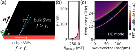
Let us consider a semi-infinite permalloy (Py) film of thickness nm, that is magnetized in the film plane perpendicularly to its edge (Fig. 1(a)). Due to dipolar interactions, a static demagnetizing field locally lowers the value of the effective magnetic field near the edge (see, Fig. 1(b)). This local reduction of the internal field is utilized as a channel along which E-SWs, can propagate. This localization at the film edge distinguishes E-SWs from B-SWs spreading through the whole film. The dispersion relation for the investigated thin film with the saturation magnetization kA/m, the exchange stiffness constant pJ/m, and the reduced damping constant , being magnetized by the bias magnetic field of value T directed along the -axis is calculated using mumax3 environmentVansteenkiste et al. (2014). Details of simulations can be found in the supplementary materials. In these simulations, SWs are excited by the local point-source-like microwave pulse of the out-of-plane directed magnetic field located at the edge of film at the point . The field used for the excitation is described by the following function, , where GHz is the cut-off frequency, is the time-delay, and the point-source-like spatial profile of the microwave field is defined by the function with nm2 describing its size. The resulting dispersion relation corresponds to the averaged over the -coordinate the absolute value of two-dimensional fast Fourier transform (FFT) of the out-of-plane component of the reduced magnetization vector () over time and the -coordinate for all values of considered in the simulations, i.e., (we denote as the -component of the reduced magnetization , where and ). In the obtained dispersion relation, shown in Fig. 1(c), we can see the brightened parabolic area for GHz ( is a bottom of B-SW band), which corresponds to the continuum of B-SWs. Besides, there is also a single frequency band, shifted downward from the B-SWs by circa 6 GHz, associated with the E-SWs. This 6 GHz wide gap separating both types of SWs at means that within the frequency range from 10.5 GHz up to 16.5 GHz only the E-SWs can be excited.
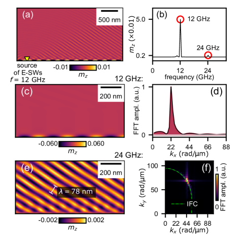
To verify the possibility of the E-SW excitation, we excite magnetization dynamics by the out-of-plane microwave magnetic field in the form , where GHz and mT. The corresponding result of micromagnetic simulations in the steady-state, i.e., after long, continuous excitation, is shown in Fig. 2(a), where color corresponds to the amplitude of the -component of the reduced magnetization, . The position of the source of SWs, i.e., the point , is indicated by the yellow triangle. First of all, we can observe an intense, circa 20 nm wide, narrow beam of SWs propagating along the edge. This is an E-SW. We can also see less intense plane waves propagating obliquely from the edge. Their amplitude is circa 20 times smaller than the maximal amplitude of E-SWs in the vicinity of the film edge. It is an unobvious result since there are no available solutions for the B-SWs at the frequency of excitation. In order to explain the origin of these plane waves we determine the SW spectrum using FFT over time, see Fig. 2(b). Namely, we present there, the maximal amplitude at a given frequency in the system, . Indeed, we can see two main peaks, the most prominent one corresponds to the frequency of the excitation (12 GHz), whereas, the second peak corresponds to its doubled frequency (24 GHz). There is also visible a small peak at a frequency around 10.5 GHz, which corresponds to the uniform resonant edge mode, that is excited during the initiation of the SW excitation. This spectrum confirms the generation of the second harmonic of the E-SW.
The mode profiles of the component of magnetization at 12 GHz and 24 GHz are presented in Fig. 3(a) and (b), respectively. Indeed, the mode at 12 GHz corresponds to the E-SWs, whereas the mode at 24 GHz corresponds to the plane-wave B-SWs propagating obliquely outwards the film’s edge. The wavelength of the B-SWs is equal to nm, whereas the wavelength of the E-SWs is equal to nm. It means that by utilization of 285-nm-long E-SWs ( rad/µm) we were able to excite 3.6 times shorter B-SWs at doubled frequency. This result is similar to the observation reported by Sebastian et al. Sebastian et al. (2013), where the second harmonic excitation of caustic beams, present only for the dipolar SWs, by the E-SWs in a 5 µm-wide waveguide was observed. This is in contrast to our research, where we show the excitation of short, exchange-dominated SWs in a semi-infinite film propagating at the oblique direction. Another similar result was reported by Hermsdoerfer et al. Hermsdoerfer et al. (2009) who used the oscillations of the domain wall to excite B-SWs with doubled the frequency of the domain wall oscillation.
The conversion of wavelengths can be better understood by transforming the real-space profiles of modes at frequencies 12 GHz and 24 GHz into the wavevector space, see Fig. 2(d) and (f), respectively. We see that the SW at frequency 12 GHz in -space is represented by a single peak at rad/µm corresponding to the propagation of 285 nm long waves along the -axis. In the case of 24 GHz mode we can also distinguish a single peak at (44 rad/µm, 68 rad/µm). It means that the value of tangential component of the B-SW wavevector () is doubled with respect to E-SWs, . The value of the , on the other hand, must take the value to satisfy the SW dispersion relation of the thin film. The available wavevectors at a given frequency are represented by the isofrequency contour [IFC, marked by the green dash-dotted line in Fig. 3(d)] being a cross-section of the dispersion relation surface at the selected frequency. In order to calculate IFC at GHz we use the analytical formula for dispersion relation of SWs in the in-plane magnetized thin film derived by Kalinikos and Slavin Kalinikos and Slavin (1986):
| (1) |
where is the permeability of vacuum, is the exchange length, , and , and is the angle between the wavevector and the external magnetic field. The term is defined as:
where .
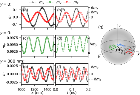
Let us look at this phenomenon from a more classical point of view and compare the magnetization oscillations at the very film edge (at ) where E-SWs propagates, and along the line positioned 300 nm from the edge, where only B-SW can be present. For , the - and -dependence of the transverse and magnetization components are presented in Fig. 3 (a) and (b), respectively, whereas the - and -dependence of the longitudinal quasistatic magnetization component are presented in Fig. 3 (c) and (d). Due to the high amplitude of the E-SWs, the -component of magnetization being aligned with the direction of the static external magnetic field oscillates with twice higher spatial and temporal frequency. This nonlinear effect is due to the ellipticity of the magnetization precession in thin film. Interestingly, when we plot the or transverse components of magnetization at nm (see Fig. 3 (e) and (f)), we obtain oscillations along the -axis with the same spatial and temporal frequencies, as respective oscillations presented in Fig. 3 (c) and (d)) (it is consistent with SW profiles presented in Fig. 2). Importantly, the peak-to-peak magnitudes of these magnetization component oscillations are relatively similar, i.e., 0.006 vs. 0.004. It means that the oscillations of the quasi-static component of magnetization at the film edge are responsible for the excitation of the propagating bulk SWs, since they have the same frequency and wavevector component . Moreover, comparing the magnetization precession components and for and nm, it can be observed that the ellipticity of magnetic moment precession is bigger for E-SWs than for B-SWs, i.e., vs. , respectively.
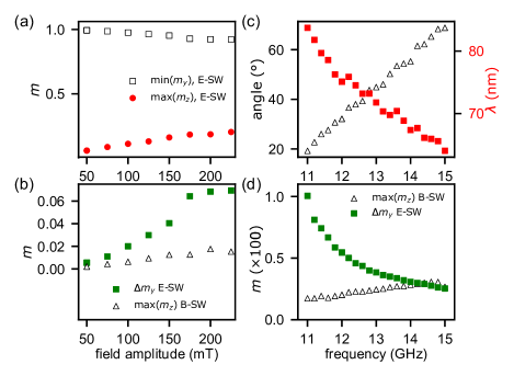
In order to verify how the emission of B-SWs depends on the amplitude and frequency of the microwave field exciting E-SWs, we have performed a series of micromagnetic simulations with the microwave point-source. Firstly, we have studied how the amplitude of E-SWs and B-SWs depends on the amplitude of the microwave field at frequency 12 GHz, see Fig. 4(a) and (b), respectively. Bigger amplitude of the microwave field results in bigger amplitude of the E-SWs and B-SWs, which is true up to 180 mT. In this range the the ratio the output B-SW intensity to the input microwave field intensity reaches ca. 0.2%111The effectiveness has been estimated as the ratio of output intensity of SWs to the input intensity of the peak pumping field for data taken from Fig. 3 and Fig. 4 a-b. For the microwave field amplitude larger than 180 mT the process saturates and at the amplitude of reduced magnetization component oscillations is set at the level 0.2, whereas the peak-to-peak magnitude of oscillations [] reaches circa 0.06. At the same time at nm the amplitude of the magnetization component oscillations reaches the value of almost 0.002. This means that the efficiency of the excitation of the B-SWs by the E-SWs is limited and the amplitude of E-SW and B-SW saturates above the threshold microwave magnetic field amplitude due to nonlinear parametric excitation of high- SWsBauer et al. (2015).
The results of simulations showing how the parameters of the excited B-SWs depend on the frequency of microwave field at amplitude 50 mT are shown in Fig. 4(c)-(d). As the excitation frequency increases, the angle of B-SWs increases, i.e., with higher frequency the propagation of the B-SWs is more parallel to the film edge.. We note that for the frequencies within the range 11 – 15 GHz the tunability of the angles of B-SW propagation in the range of 50∘ is achieved. As easy to predict, the wavelength of the excited B-SW decreases with the rise of the frequency (85 nm at 11 GHz and 65 nm at 15 GHz). The excitation frequency increase results in a slight increase in amplitude of the B-SWs and significant decrease of the peak-to-peak amplitude of the component . The decrease of is due to the decreasing efficiency of the E-SW excitation by the microwave source for shorter E-SW.
Although the presented results were obtained with the use of point-source of the microwave field, the additional simulations made with the microwave magnetic field profiles that approximate microstrip antenna oriented along the -axis ( and nm2) at 50 mT and 170 mT amplitudes are qualitatively very similar to the point-source results. Regarding the propagation distance of the considered SWs for the assumed value of , we estimated that the E-SW propagate up to 76 µm at 12 GHz at low amplitude of microwave field. The distance decreases with increasing the amplitude and at 50 mT of the microwave field the E-SW decay length is around 20 µm. It points at the feasibility of the experimental realization of the nonlinear excitation of short B-SWs by microstrip generated E-SWs, as well as spin-torque point contacts.
Summarizing, we have presented a method that allows to excite sub-100 nm-long SWs in the form of traveling plane waves. These waves are excited in nonlinear process by E-SWs, which possess strong ellipticity of magnetic moments precession. This causes the spatial and temporal frequency of the longitudinal magnetization component, normal to the edge, to be doubled with respect to the edge mode. The plane waves are excited by the oscillations of the quasi-static magnetization component. Their length and propagation direction is a direct consequence of the requirement for conservation of the tangential to the edge component of the wavevector. This effect can be understood as a local nonlinear excitation of plane-wave SWs propagating in a thin film with edge-localized SW modes. The high frequency and short wavelength of exciting plane waves, combined with a simplicity of the method and feasibility for miniaturization of the system size to sub-µm range, promise usefulness of the proposed mechanism for magnonic applications.
Suplementary material
See the supplementary material for the details of micromagnetic simulations.
Acknowledgements.
The research leading to these results has received funding from the National Science Centre of Poland, project no. 2019/35/D/ST3/03729. I.L.L. acknowledges support by COST action under project CA17123 MAGNETOFON. K.Y.G. acknowledges support by IKERBASQUE (the Basque Foundation for Science) and by the Spanish Ministerio de Ciencia, Innovacion y Universidades grant PID2019-108075RB-C3-3. The simulations were partially performed at the Poznan Supercomputing and Networking Center (Grant No. 398).DATA AVAILABILITY
The data that support the findings of this study are available from the corresponding author upon reasonable request.
References
- Gurevich and Melkov (1996) A. G. Gurevich and G. A. Melkov, Magnetization oscillations and waves (CRC Press, Boca Raton, 1996).
- Barman et al. (2020) A. Barman, S. Mondal, S. Sahoo, and A. De, “Magnetization dynamics of nanoscale magnetic materials: A perspective,” J. Appl. Phys. 128, 170901 (2020).
- Chumak et al. (2015) A. Chumak, V. Vasyuchka, A. Serga, and B. Hillebrands, “Magnon spintronics,” Nat. Phys. 11, 453–461 (2015).
- Gieniusz et al. (2017) R. Gieniusz, P. Gruszecki, M. Krawczyk, U. Guzowska, A. Stognij, and A. Maziewski, “The switching of strong spin wave beams in patterned garnet films,” Sci. Rep. 7, 1–8 (2017).
- Davies et al. (2015) C. S. Davies, A. Francis, A. V. Sadovnikov, S. V. Chertopalov, M. T. Bryan, S. V. Grishin, D. A. Allwood, Y. P. Sharaevskii, S. A. Nikitov, and V. V. Kruglyak, “Towards graded-index magnonics: Steering spin waves in magnonic networks,” Phys. Rev. B 92, 020408 (2015).
- Gruszecki and Krawczyk (2018) P. Gruszecki and M. Krawczyk, “Spin-wave beam propagation in ferromagnetic thin films with graded refractive index: Mirage effect and prospective applications,” Phys. Rev. B 97, 094424 (2018).
- Gruszecki et al. (2014) P. Gruszecki, J. Romero-Vivas, Y. S. Dadoenkova, N. N. Dadoenkova, I. L. Lyubchanskii, and M. Krawczyk, “Goos-Hänchen effect and bending of spin wave beams in thin magnetic films,” Appl. Phys. Lett. 105, 242406 (2014).
- Sebastian et al. (2013) T. Sebastian, T. Brächer, P. Pirro, A. A. Serga, B. Hillebrands, T. Kubota, H. Naganuma, M. Oogane, and Y. Ando, “Nonlinear emission of spin-wave caustics from an edge mode of a microstructured Co2Mn0.6Fe0.4Si waveguide,” Phys. Rev. Lett. 110, 067201 (2013).
- Davies, Poimanov, and Kruglyak (2017) C. S. Davies, V. D. Poimanov, and V. V. Kruglyak, “Mapping the magnonic landscape in patterned magnetic structures,” Phys. Rev. B 96, 094430 (2017).
- Dadoenkova et al. (2019) N. N. Dadoenkova, Y. S. Dadoenkova, I. L. Lyubchanskii, M. Krawczyk, and K. Y. Guslienko, “Inelastic spin-wave scattering by Bloch domain wall flexure oscillations,” Phys. Status Solidi RRL 13, 1800589 (2019).
- Zhang et al. (2018) B. Zhang, Z. Wang, Y. Cao, P. Yan, and X. Wang, “Eavesdropping on spin waves inside the domain-wall nanochannel via three-magnon processes,” Phys. Rev. B 97, 094421 (2018).
- Schlömann, Green, and Milano (1960) E. Schlömann, J. J. Green, and u. Milano, “Recent developments in ferromagnetic resonance at high power levels,” J. Appl. Phys. 31, S386–S395 (1960).
- Brächer, Pirro, and Hillebrands (2017) T. Brächer, P. Pirro, and B. Hillebrands, “Parallel pumping for magnon spintronics: Amplification and manipulation of magnon spin currents on the micron-scale,” Phys. Rep 699, 1 – 34 (2017).
- Demidov et al. (2011a) V. E. Demidov, M. P. Kostylev, K. Rott, P. Krzysteczko, G. Reiss, and S. O. Demokritov, “Generation of the second harmonic by spin waves propagating in microscopic stripes,” Phys. Rev. B 83, 054408 (2011a).
- Rousseau et al. (2014) O. Rousseau, M. Yamada, K. Miura, S. Ogawa, and Y. Otani, “Propagation of nonlinearly generated harmonic spin waves in microscopic stripes,” J. Appl. Phys. 115, 053914 (2014).
- Demidov et al. (2011b) V. E. Demidov, H. Ulrichs, S. Urazhdin, S. O. Demokritov, V. D. Bessonov, R. Gieniusz, and A. Maziewski, “Resonant frequency multiplication in microscopic magnetic dots,” Appl. Phys. Lett. 99, 012505 (2011b).
- Marsh et al. (2012) J. Marsh, V. Zagorodnii, Z. Celinski, and R. E. Camley, “Nonlinearly generated harmonic signals in ultra-small waveguides with magnetic films: Tunable enhancements of 2nd and 4th harmonics,” Appl. Phys. Lett. 100, 102404 (2012).
- IRD (2020) “Beyond CMOS,” International Roadmap for Devices and Systems (IRDS™) 2020 Edition (2020).
- Mahmoud et al. (2020) A. Mahmoud, F. Ciubotaru, F. Vanderveken, A. V. Chumak, S. Hamdioui, C. Adelmann, and S. Cotofana, “Introduction to spin wave computing,” J. Appl. Phys. 128, 161101 (2020).
- Ciubotaru et al. (2016) F. Ciubotaru, T. Devolder, M. Manfrini, C. Adelmann, and I. Radu, “All electrical propagating spin wave spectroscopy with broadband wavevector capability,” Appl. Phys. Lett. 109, 012403 (2016).
- Gruszecki et al. (2016) P. Gruszecki, M. Kasprzak, A. E. Serebryannikov, M. Krawczyk, and W. Śmigaj, “Microwave excitation of spin wave beams in thin ferromagnetic films,” Sci. Rep. 6, 22367 (2016).
- Yu et al. (2013) H. Yu, G. Duerr, R. Huber, M. Bahr, T. Schwarze, F. Brandl, and D. Grundler, “Omnidirectional spin-wave nanograting coupler,” Nat. Commun. 4, 2702 (2013).
- Yu et al. (2019) T. Yu, C. Liu, H. Yu, Y. M. Blanter, and G. E. Bauer, “Chiral excitation of spin waves in ferromagnetic films by magnetic nanowire gratings,” Phys. Rev. B 99, 134424 (2019).
- Baumgaertl et al. (2020) K. Baumgaertl, J. Grafe, P. Che, A. Mucchietto, J. Frorster, N. Trager, M. Bechtel, M. Weigand, G. Schutz, and D. Grundler, “Nanoimaging of ultrashort magnon emission by ferromagnetic grating couplers at ghz frequencies,” Nano Lett. 20, 7281 (2020).
- Van de Wiele et al. (2016) B. Van de Wiele, S. J. Hämäläinen, P. Baláž, F. Montoncello, and S. Van Dijken, “Tunable short-wavelength spin wave excitation from pinned magnetic domain walls,” Sci. Rep. 6, 21330 (2016).
- Mushenok et al. (2017) F. B. Mushenok, R. Dost, C. S. Davies, D. A. Allwood, B. J. Inkson, G. Hrkac, and V. V. Kruglyak, “Broadband conversion of microwaves into propagating spin waves in patterned magnetic structures,” Appl. Phys. Lett. 111, 042404 (2017).
- Whitehead et al. (2017) N. J. Whitehead, S. A. R. Horsley, T. G. Philbin, A. N. Kuchko, and V. V. Kruglyak, “Theory of linear spin wave emission from a Bloch domain wall,” Phys. Rev. B 96, 064415 (2017).
- Träger et al. (2019) N. Träger, P. Gruszecki, F. Lisiecki, F. Groß, J. Förster, M. Weigand, H. Głowiński, P. Kuświk, J. Dubowik, G. Schütz, et al., “Real space observation of magnon interaction with driven space-time crystals,” arXiv preprint arXiv:1911.13192 (2019).
- Houshang et al. (2018) A. Houshang, R. Khymyn, H. Fulara, A. Gangwar, M. Haidar, S. Etesami, R. Ferreira, P. Freitas, M. Dvornik, R. Dumas, et al., “Spin transfer torque driven higher-order propagating spin waves in nano-contact magnetic tunnel junctions,” Nat. Commun. 9, 1–6 (2018).
- Fulara et al. (2019) H. Fulara, M. Zahedinejad, R. Khymyn, A. Awad, S. Muralidhar, M. Dvornik, and J. Åkerman, “Spin-orbit torque–driven propagating spin waves,” Sci. Adv. 5, eaax8467 (2019).
- Lara, Metlushko, and Aliev (2013) A. Lara, V. Metlushko, and F. G. Aliev, “Observation of propagating edge spin waves modes,” J. Appl. Phys. 114, 213905 (2013).
- Lara et al. (2017) A. Lara, J. R. Moreno, K. Y. Guslienko, and F. G. Aliev, “Information processing in patterned magnetic nanostructures with edge spin waves,” Sci. Rep. 7, 1–12 (2017).
- Vansteenkiste et al. (2014) A. Vansteenkiste, J. Leliaert, M. Dvornik, M. Helsen, F. Garcia-Sanchez, and B. Van Waeyenberge, “The design and verification of mumax3,” AIP Adv. 4, 107133 (2014).
- Hermsdoerfer et al. (2009) S. J. Hermsdoerfer, H. Schultheiss, C. Rausch, S. Schäfer, B. Leven, S.-K. Kim, and B. Hillebrands, “A spin-wave frequency doubler by domain wall oscillation,” Appl. Phys. Lett. 94, 223510 (2009).
- Kalinikos and Slavin (1986) B. A. Kalinikos and A. N. Slavin, “Theory of dipole-exchange spin wave spectrum for ferromagnetic films with mixed exchange boundary conditions,” J. Phys. C: Solid State Phys. 19, 7013 (1986).
- Note (1) The effectiveness has been estimated as the ratio of output intensity of SWs to the input intensity of the peak pumping field for data taken from Fig. 3 and Fig. 4 a-b.
- Bauer et al. (2015) H. Bauer, P. Majchrak, T. Kachel, C. H. Back, and G. Woltersdorf, “Nonlinear spin-wave excitations at low magnetic bias fields,” Nat. Commun. 6, 8274 (2015).