Reversible giant out-of-plane Rashba effect in two-dimensional Ga (= Se, Te; = Cl, Br, I) compounds for persistent spin helix
Abstract
The coexistence of ferroelectricity and spin-orbit coupling (SOC) in noncentrosymmetric systems may allow for a nonvolatile control of spin degrees of freedom by switching the ferroelectric polarization through the well-known ferroelectric Rashba effect (FRE). Although the FER has been widely observed for bulk ferroelectric systems, its existence in two-dimensional (2D) ferroelectric systems is still very rarely discovered. Based on first-principles calculations, supplemented with analysis, we report the emergence of the FRE in the Ga (= Se, Te; = Cl, Br, I) monolayer compounds, a new class of 2D materials having in-plane ferroelectricity. Due to the large in-plane ferroelectric polarization, a giant out-of-plane Rashba effect is observed in the topmost valence band, producing unidirectional out-of-plane spin textures in the momentum space. Importantly, such out-of-plane spin textures, which can host a long-lived helical spin mode known as a persistent spin helix, can be fully reversed by switching the direction of the in-plane ferroelectric polarization. Thus, our findings can open avenues for interplay between the unidirectional out-of-plane Rashba effect and the in-plane ferroelectricity in 2D materials, which is useful for efficient and non-volatile spintronic devices.
pacs:
Valid PACS appear hereI INTRODUCTION
During the last decade, spin-orbit coupling (SOC) has attracted increasing interest in various fields, including spintronics, quantum computing, topological matter, and cold atom systemsManchon et al. (2015); Varignon et al. (2018). In particular, the SOC links the spin degree of freedom to the orbital motion of electrons in a solid without additional external magnetic field, thus playing an important role in semiconductor-based spintronicsManchon et al. (2015); Varignon et al. (2018); Ganichev and Golub (2014). For a system with a lack of inversion symmetry, the SOC induces an effective magnetic field, which results in spin-splitting bands and non-trivial spin textures in the momentum space, known as the Rashba Rashba (1960) and DresselhausDresselhaus (1955) effects. The Rashba effect has been widely observed on a system having structural inversion asymmetry such as semiconductor quantum well Nitta et al. (1997); Caviglia et al. (2010), surface heavy metalKoroteev et al. (2004); LaShell et al. (1996), and several two-dimensional (2D) layered compoundsZhuang et al. (2015); Popović et al. (2015); Absor et al. (2018); Affandi and Ulil Absor (2019); Absor et al. (2017), while the Dresselhaus effect occurs on a system hold bulk inversion asymmetries such as bulk zincblendeDresselhaus (1955) and wurtzite semiconductorsWang et al. (2007). Recently, ferroelectric materials have witnessed a surge of interest in the field of spintronics since they enable integration of the SOC and ferroelectricity through the well-known ferroelectric Rashba effect (FRE)Picozzi (2014). In such functionality, the spin textures of the spin-splitting bands can be fully reversed in a non-volatile way by switching the direction of the ferroelectric polarization. As such, the FER is very promising for spintronic devices implementing, for instant, tunneling anomalous and spin Hall effects Vedyayev et al. (2013); Matos-Abiague and Fabian (2015). The FER was first predicted theoretically in bulk GeTe Di Sante et al. (2012) and experimentally confirmed in GeTe thin-filmLiebmann et al. (2016); Rinaldi et al. (2018). After that, numerous candidates for FRE materials have been recently proposed, which mainly comes from the bulk metal-organic halide perovskite, including (FA)SnI3 Stroppa et al. (2014); Kepenekian et al. (2015), hexagonal semiconductors (LiZnSb)Narayan (2015), and oxides (KTaO3Tao and Wang (2016), HfO2Tao et al. (2017), BiAlO3da Silveira et al. (2016)).
While the FRE has been widely studied for the bulk ferroelectric materialsPicozzi (2014); Di Sante et al. (2012); Stroppa et al. (2014); Kepenekian et al. (2015); Narayan (2015); Tao and Wang (2016); Tao et al. (2017); da Silveira et al. (2016), due to favorable spintronic applications in nanoscale devices Ahn (2020); Han (2016), ultrathin two-dimensional (2D) materials supporting the FRE would be more desirable. However, the small thickness in the 2D materials may lose the FRE functionality since the ferroelectric polarization is suppressed by an enormous depolarizing field Junquera and Ghosez (2003); Gao et al. (2017). Recently, a new class of 2D materials exhibiting robust ferroelasticity and ferroelectricity has been reported, which comes from Ga (= Se, Te; = Cl, Br, I) monolayer (ML) compounds Zhou et al. (2018); Zhang and Liu (2018). These compounds are stable under room temperature exhibiting the large in-plane ferroelectricity Zhou et al. (2018); Zhang and Liu (2018); Wu et al. (2019); Absor and Ishii (2021). Moreover, due to the strong SOC in these materials, the large band splitting with tunable spin polarization in the conduction band minimum have recently been predicted Absor and Ishii (2021). In addition to the observed large spin splitting in the Ga ML compounds, the SOC induces doubly degenerate nodal loops featuring an hourglass type dispersion has also been reported Wu et al. (2019). Considering the fact that the Ga ML exhibits large in-plane ferroelectricity and strong SOC, it is expected that achieving the FRE in these materials is highly plausible, which is expected to be useful for spintronic applications.
In this paper, through first-principles density-functional theory (DFT) calculations, complemented with analysis, we predict the emergence of the FRE in the 2D Ga ML compounds. We find that due to the large in-plane ferroelectric polarization in the Ga ML, a giant out-of-plane Rashba effect is observed in the topmost valence band, exhibiting unidirectional out-of-plane spin textures in the momentum space. Importantly, such out-of-plane spin textures, which can host a long-lived helical spin mode known as a persistent spin helix (PSH), can be fully reversed by switching the direction of the in-plane ferroelectric polarization. Moreover, the physical mechanism of the FRE found in the present system is well analyzed within the framework of the Hamiltonian model incorporating the in-plane ferroelectricity and point group symmetry of the crystal. Finally, a possible implication of the reversible spin textures of the present system for spintronics will be discussed.
II Computational details
We have performed first-principles DFT calculations using the OpenMX codeOzaki (2003); Ozaki et al. (2009); Ozaki and Kino (2004, 2005), based on norm-conserving pseudo-potentials and optimized pseudo-atomic localized basis functions. The exchange-correlation functional was treated within generalized gradient approximation by Perdew, Burke, and Ernzerhof (GGA-PBE)Perdew et al. (1996); Kohn and Sham (1965). The basis functions were expanded by linear combination of multiple pseudo atomic orbitals generated using a confinement scheme Ozaki (2003); Ozaki and Kino (2004), where two -, two -, two -character numerical pseudo atomic orbitals were used. The accuracy of the basis functions as well as pseudo-potentials we used were carefully bench-marked by the delta gauge method Lejaeghere et al. (2016).
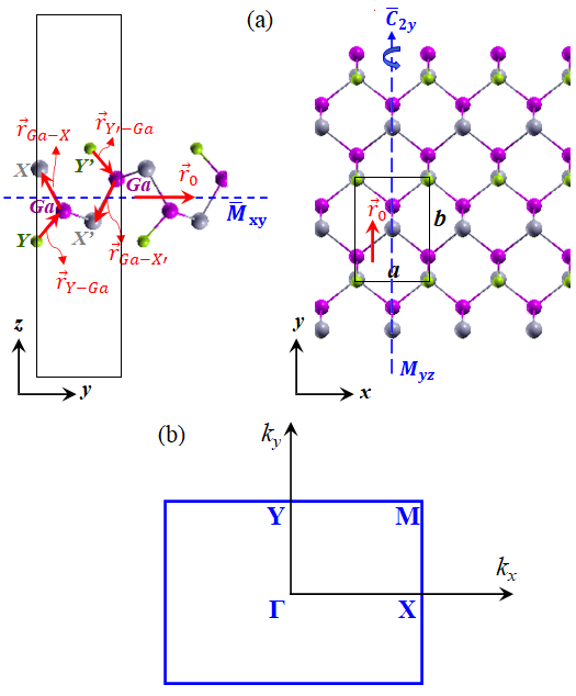
We applied a periodic slab to model the Ga ML, where a sufficiently large vacuum layer (20 Å) was applied in order to avoid the spurious interaction between slabs [Fig. 1(a)]. The -point mesh was used to discretize the first Brillouin zone (FBZ) [Fig. 1(b)]. We adopted the modern theory of polarization based on the Berry phase (BP) method King-Smith and Vanderbilt (1993) implemented in the OpenMX code to calculate the ferroelectric polarization. During the structural relaxation, the energy convergence criterion was set to eV. The lattice and positions of the atoms were optimized until the Hellmann-Feynman force components acting on each atom was less than 1 meV/Å.
The SOC was included self consistently in all calculations by using -dependent pseudo potentials (Theurich and Hill, 2001). We calculated the spin textures by deducing the spin vector components (, , ) in the reciprocal lattice vector from the spin density matrixKotaka et al. (2013). The spin density matrix, , were calculated using the following relation,
| (1) |
where is the spinor Bloch wave function. This methods has been successfully applied on our recent studies on various 2D materialsAnshory and Absor (2020); Absor and Ishii (2019a, b); Absor et al. (2020); Absor and Ishii (2021); Absor et al. (2021).
III Results and Discussion
III.1 Atomic structure, symmetry, and ferroelectricity
| Ga ML | (Å) | (Å) | (Å) | (Å) | (Å) | (pC/m) |
|---|---|---|---|---|---|---|
| GaSeCl | 3.87 | 5.53 | 2.47 | 2.23 | 0.23 | 478.9 |
| GaSeBr | 3.95 | 5.63 | 2.47 | 2.37 | 0.15 | 459.1 |
| GaSeI | 4.17 | 5.93 | 2.49 | 2.60 | 0.08 | 352.5 |
| GaTeCl | 4.17 | 5.93 | 2.70 | 2.26 | 0.33 | 542.6 |
| GaTeBr | 4.26 | 6.08 | 2.71 | 2.37 | 0.28 | 530.1 |
| GaTeI | 4.41 | 6.33 | 2.73 | 2.61 | 0.25 | 519.8 |
First, we characterize the optimized structural parameters, symmetry of the crystal, and ferroelectricity of the Ga ML compounds, where the atomic structure is displayed in Fig. 1(a). The crystal structure of the Ga ML is noncentrosymmetric having a black-phosphorene-type structure belonging to space group Zhou et al. (2018); Zhang and Liu (2018); Wu et al. (2019); Absor and Ishii (2021); Kniep et al. (1983). For the convenience ofdiscussion, we choose the () axis to be along the zigzag (armchair) direction in the real space so that the reciprocal space is characterized by the FBZ as shown in Fig. 1(b). There are six atoms in the unit cell consisted of two Ga atoms, two chalcogen atoms (labeled by and ), and two halogen atoms (labeled by and ). These atoms are invariant under the following symmetry operations: (i) identity operation , (ii) the glide reflection consisted of reflection about plane followed by translation along the axis and translation along the axis, where and is the lattice parameters of the crystal, (iii) the twofold screw rotation defined as rotation around line followed by translation along the axis, and (iv) the mirror reflection around the plane. The optimized lattice parameters (, ) for each Ga ML compound are listed in Table 1. We find that due to the difference value between the and parameters, the crystal geometry of the Ga ML is anisotropic, implying that these materials have different mechanical responses being subjected to uniaxial strain along the - and -direction similar to that observed on various group IV monochalcogenideAnshory and Absor (2020); Kong et al. (2018); Liu et al. (2019).
The atomic structure of the Ga ML can be viewed as Ga ML surface functionalized by halogen () atoms bonded to the Ga atoms forming a sandwiched structure with -Ga- sequence [see Fig. 1(a)]. We then introduce a distortion vector, , defined as
| (2) |
where and are the vectors connected the Ga atom to chalcogen atom and the halogen atom to Ga atom, respectively, in the unit cell [see left side in Fig. 1(a)]. Here, the magnitude and represent the Ga-() and ()-Ga bond lengths, respectively. Due to the mirror symmetry operation along the plane, we obtain that , while the screw operation implies that . Accordingly, should be parallel to the in-plane direction and induces intrinsic spontaneous polarization along the direction. Generally, the optimized structures of the Ga ML compounds show that the bond lengths are larger than the bond lengths [see Table I]. However, the bond lengths substantially increases for the compounds with the same chalcogen () atoms but have the heavier halogen () atoms, thus decreasing the magnitude of the distortion vector, . Therefore, the decreased in magnitude of the in-plane electric polarization is expected, which is in fact confirmed by our BP calculation results shown in Table I. The existence of the in-plane ferroelectricity allows us to maintain the FRE in the Ga ML compounds, which is expected to be observed due to the large SOC.
In the next section, we will show how the in-plane ferroelectricity plays an important role in the SOC and electronic properties of the Ga ML compounds.
III.2 Spin-orbit coupled ferroelectric and spin textures
We will start our analysis by deriving the general SOC Hamiltonian in the 2D systems having in-plane ferroelectricity. The SOC Hamiltonian is further analyzed for the Ga ML compounds within the framework of the Hamiltonian model using the method of invariantWinkler et al. (2003). Finally, we discuss the important implication of the derived SOC Hamiltonian in terms of the spin splitting and spin textures involving to the in-plane ferroelectricity.
The SOC occurs in solid-state materials when an electron moving at velocity through an electric field experiences an effective magnetic field due to the relativistic transformation of electromagnetic fields. A general form of the SOC Hamiltonian can be expressed as:
| (3) |
where are the Pauli matrices and is a wave-vector dependent spin-orbit field (SOF) that is simply written as
| (4) |
where is the strength of the SOC that is proportional to the magnitude of the electric field, , denotes the electric filed direction, and is the wave vector representing the momentum electron. The is invariant under time reversal symmetry operations, , so that the following relation holds, . Accordingly, the SOF is a odd in wave vector , i.e. , which also depends on the crystal symmetry of the system.
Lets us consider the general 2D systems having in-plane ferroelectricity, where we assumed that the spontaneous in-plane electric polarization being oriented along the in-plane -direction. In this case, an effective electric field is induced, which is also oriented along the -directions, . Due to the 2D nature of the systems, we have for the wave vector , and by using the explicit form of the effective electric field , we find that the SOF in Eq. (4), can be expressed as
| (5) |
We can see that for the 2D systems having in-plane ferroelectricity, the SOF is enforced to be unidirectional in the out-of-plane direction. Inserting the Eq. (4) to the Eq. (3), we find that
| (6) |
The Eq. (6) clearly shows that the is characterized only by one component of the wave vector and the out-of-plane spin vector , yielding a unidirectional out-of-plane Rashba effect.
| Symmetry | Invariants | ||
| Operations | |||
| () | |||
| , , | |||
| , , | |||
| , |
The in Eq. (6) is also obtained by considering the wave-vector symmetry group at the high symmetry points in the first-Brillouin zone. Here, we assumed that only linear terms with respect to the wave vector contribute to the . For the case of the Ga ML compounds, the wave-vector symmetry group of the space group at the high symmetry points such as , , and points, belongs to point groupAbsor and Ishii (2021), which has two mirror reflections about the plane () and the plane () as well as twofold rotation around the -axis. The transformation rules for the wave vector and spin vector under the considered point-group symmetry operations are listed in Table II. By applying the methods of invariantWinkler et al. (2003), we list all the invariant term of the in the form of product between the and components (see the right column in Table II) and select those specific terms which are invariant under all symmetry operations as indicated by the underlined terms in the right column in Table II. We find that only term of the is invariant under all symmetry operations of the , which is identical to the shown in Eq. (6).
Next, we characterize low energy properties of the present system involving the term of Eq. (6). The effective Hamiltonian including the kinetic and terms can be expressed as
| (7) |
Solving eigenvalue problem involving the Hamiltonian of Eq. (7) leads to the eigenstates
| (8) |
and
| (9) |
corresponding to the energy dispersion,
| (10) |
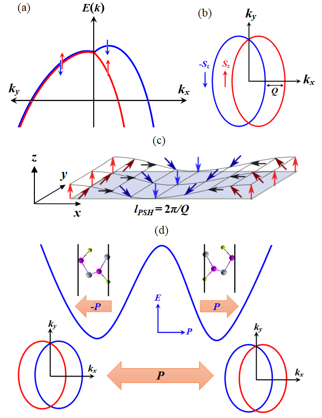
This dispersion indicates that a strongly anisotropic spin splitting occurs around the point, i.e., the energy bands are lifted along direction but are degenerated along the direction [Fig. 2(a)]. Importantly, this dispersion is characterized by the shifting property, , where the is the shifting wave vector given by
| (11) |
The Eqs. (10) and (11) implies that a constant-energy cut shows two Fermi loops whose centers are displaced from their original point by as schematically shown in Fig. 2(b).
The spin texture, which is -dependent spin configuration, is determined from the expectation values of the spin operators, i.e., , where is the electron’s eigenstates. By using given in Eqs. (8) and (9), we find that
| (12) |
This shows that the spin configuration in the -space is locked being oriented in the out-of-plane directions as schematically shown in Fig. 2(b). Such a typical spin configuration forms a persistent spin textures (PST) similar to that observed for [110] Dresselhauss modelBernevig et al. (2006). Previously, it has been reported that the PST is known to host a long-lived helical spin mode known as a persistent spin helix (PSH) Bernevig et al. (2006); Altmann et al. (2014); Schliemann (2017), enabling long-range spin transport without dissipationBernevig et al. (2006); Altmann et al. (2014); Schliemann (2017); Kohda et al. (2012); Walser et al. (2012); Koralek et al. (2009), and hence very promising for an efficient spintronic devices.
The PSH arises when the SOF is unidirectional, preserving a unidirectional spin configuration in the -space. When an electron moving in the real space is accompanied by the spin precession around the SOF, a spatially periodic mode of the spin polarization is generated. According to Eq. (5), the magnitude of the effective magnetic field can be expressed as , where is the gyromagnetic ratio. Therefore, the angular frequency of the precession motion, , can be calculated using the relation, . The spin precession angle, , around the axis at time , is obtained by . At the same time, the traveling distance of the electron is given by , where is the electron velocity. By eliminating , we find that . When , we then obtain the wavelength of the PSH, Bernevig et al. (2006),
| (13) |
Furthermore, in term of the shifting wave vector defined in Eq. (11), we can write the as
| (14) |
A schematic picture of the PSH mode enforced by the unidirectional SOF is displayed in Fig. 2(c), where a spatially periodic mode of the spin polarization with the wavelength is shown. Such spin-wave mode protects the spins of electrons from decoherence through suppressing the Dyakonov-Perel spin relaxation mechanismDyakonov and Perel (1972) and renders an extremely long spin lifetimeBernevig et al. (2006); Altmann et al. (2014); Schliemann (2017); Kohda et al. (2012); Walser et al. (2012); Koralek et al. (2009).
Finally, we study the correlation between spin textures and ferroelectricity. Here, an important property called reversible spin textures holds, i.e., the direction of the spin textures is locked and switchable by reversing the direction of the spontaneous electric polarization. Fig. 2(d) shows a schematic view of the spin textured ferroelectric in the Ga ML compounds showing fully reversible out-of-plane spin textures. It is shown that switching the direction of the in-plane ferroelectric polarization from to leads to reversing the direction of the out-of-plane spin textures from - to -direction.
From the symmetry point of view, switching the electric polarization direction is equivalent to the space inversion symmetry operation , which changes the wave vector from to , but preserves the spin vector Kim et al. (2014). Now, suppose that is the Bloch wave function of the crystal with electric polarization . The inversion symmetry operation on the Bloch wave function hold the following relation, . Applying the time-reversal symmetry brings back to but flip the spin vector , thus . The expectation values of spin operator can be further expressed in term of and vectors as
| (15) |
which clearly shows that the spin directions is fully reversed by switching the direction of the electric polarization .
In the next section, we implement these general description of the spin-orbit coupled ferroelectric to discuss our results from the first-principles DFT calculations on various Ga ML compounds.
III.3 First-principles DFT analyses
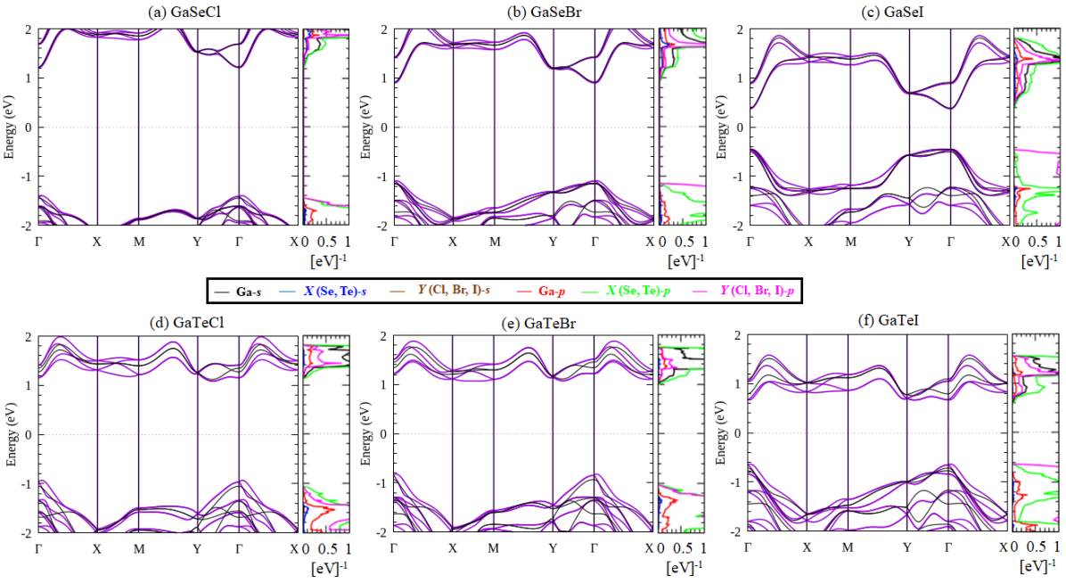
Figure 3 shows the electronic band structure of the Ga ML compounds calculated along the selected paths in the FBZ corresponding to the density of states (DOS) projected to the atomic orbitals. It is found that the Ga ML compounds are semiconductors with direct or indirect band gaps depending on the chalcogen () atoms. In the case of the GaSe MLs, the electronic band structure shows a direct bandgap where the valence band maximum (VBM) and conduction band minimum (CBM) is located at the point [Figs. 3(a)-3(c)]. The VBM at the point retains for the case of the GaTe MLs but the CBM shifts to the point along the line, resulting in an indirect bandgap [Figs. 3(d)-3(f)]. We find that the band gap significantly decreases for the compounds with the same chalcogen atoms but has the larger number of the halogen () atoms. For an instant, the calculated bandgap for the GaTeCl ML is 2.17 eV under GGA level, which is much larger than that for the GaTeI ML (1.10 eV). Our calculated DOS projected to the atomic orbitals confirmed that the VBM is mostly dominated by the contribution of the chalcogen - orbital with a small admixture of the Ga- and halogen - orbitals, while the CBM is mainly originated from the Ga- orbital with a small contribution of Ga-, chalcogen - and halogen - orbitals [Figs. 3(a)-(f)].
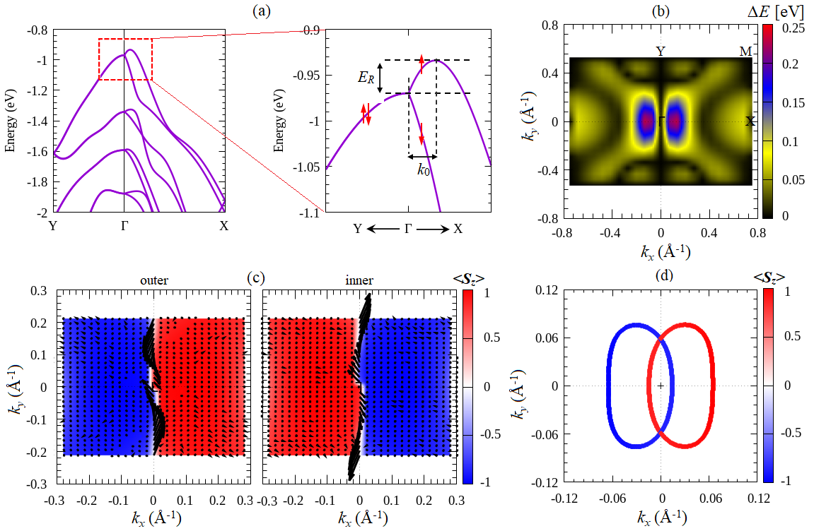
Introducing the SOC, however, strongly modifies the electronic band structures of the Ga ML compounds. Here, we observed a significant band splitting produced by the SOC due to the lack of the inversion symmetry, which is mainly visible at the bands along the symmetry lines [Figs. 3(a)-(f)]. However, along the line in which the wave vector is parallel to the effective electric field associated with the in-plane ferroelectric polarization, the bands are double degenerated. Since the electronic states near the Fermi level are important for transport carriers, we then focused our attention on the bands near the VBM. Fig. 4(a) shows the calculated band structure along the line around the VBM for GaTeCl ML as a representative example of the Ga ML compounds. At the point, the electronic states at the point are double degenerated due to time reversibility. This doublet splits into singlet when considering the bands along the line. However, the doublet remains for the along the line, which is protected by the screw rotation and the glide mirror reflection. Accordingly, a strongly anisotropic splitting is clearly observed around the point as highlighted by the red line in Fig. 4(a), which is in good agreement with the energy dispersion shown in Eq. (10) as well as Fig. 2(a).
We noted here that the remaining band degeneracy at the wave vector along the line can be explained in term of the symmetry analysis. Since the wave vector at the line is invariant under and symmetry operations, the folowing relation holds, , where the minus sign comes from the fact that both and operators are anti-commutative, due to the anti-commutation between and spin rotation operators, . Supposed that is an eigenvector of operator with the eigenvalue of , we obtain that . This evident shows that both and states are distinct states degenerated at the same energy, thus ensuring the double degeneracy of the states at the wave vector along the line. To further clarify the observed anisotropic splitting around the point, we show in Fig. 4(b) momentum-resolved map of the spin-splitting energy calculated along the entire of the FBZ. Consistent with the band structures, we identify the non-zero spin-splitting energy except for the bands along the line. Here, the largest splitting is observed at the closed to the point at along the line, where the splitting energy up to 0.25 eV is achieved. Such value is comparable with the splitting energy observed on various 2D transition metal dichalcogenides (= Mo, W; = S, Se, Te) MLs [0.15 eV - 0.46 eV] Zhu et al. (2011); Affandi and Ulil Absor (2019); Absor et al. (2017); Yao et al. (2017); Absor et al. (2016). The large splitting energy observed in the present system is certainly sufficient to ensure proper function of spintronic devices operating at room temperatureYaji et al. (2010).
| 2D materials | (eVÅ) | (nm) | Reference |
|---|---|---|---|
| Ga compounds | |||
| GaSeCl | 1.2 | 2.89 | This work |
| GaSeBr | 0.85 | 4.09 | This work |
| GaSeI | 0.53 | 6.57 | This work |
| GaTeCl | 2.65 | 1.20 | This work |
| GaTeBr | 2.40 | 1.45 | This work |
| GaTeI | 1.90 | 1.83 | This work |
| Group IV Monochalcogenide | |||
| (Sn,Ge) (= S, Se, Te) | 0.07 - 1.67 | - 1.82 | Ref.Absor and Ishii (2019a) |
| Ge (= S, Se, Te) | 3.10 - 3.93 | 6.53 - 8.52 | Ref.Absor et al. (2021) |
| Layeted SnTe | 1.28 - 2.85 | 8.80 - 18.3 | Ref.Lee et al. (2020) |
| Strained SnSe | 0.76 - 1.15 | Ref.Anshory and Absor (2020) | |
| SnSe- (= Cl, Br, I) | 1.60 - 1.76 | 1.27 - 1.41 | Ref.Absor and Ishii (2019b) |
| Defective transition metal dichalcogenides | |||
| line defect in PtSe2 | 0.20 - 1.14 | 6.33 - 28.19 | Ref.Absor et al. (2020) |
| line defect in (Mo,W)(S,Se)2 | 0.14 - 0.26 | 8.56 - 10.18 | Ref.Li et al. (2019) |
| Other 2D ML | |||
| WO2Cl2 | 0.90 | Ref.Ai et al. (2019) |
The nature of the anisotropic splitting around the point at the VBM is further analyzed by identifying the spin textures of the spin-split bands. As shown in Fig. 4(c), it is found that a uniform pattern of the spin textures is observed around the point, which is mostly characterized by fully out-of-plane spin components rather than the in-plane spin components (). These spin textures are switched from to when crossing at =0 along the line. Although we identified large in-plane spin components () in the line, the net in-plane spin polarization vanishes, which is due to the equal population of the opposite in-plane spin polarization between the outer and inner branches of the spin split bands [see black arrows in Fig. 4(c)]. Such a pattern of the spin textures, which is similar to that observed on several 2D ferroelectric materials such as WO2Cl2 Ai et al. (2019) and various group IV monochalcogenide MLs Absor and Ishii (2019a); Lee et al. (2020); Anshory and Absor (2020); Absor et al. (2021), is strongly different from the in-plane Rashba-like spin textures reported on the widely studied 2D materialsAbsor et al. (2018); Affandi and Ulil Absor (2019); Absor et al. (2017); Yao et al. (2017). Moreover, the fully out-of-plane spin texture becomes clearly visible when measured at the constant energy cut of 1 meV below the degenerated states at the VBM around the point [Fig. 4(d)]. Here, two circular loops of the Fermi lines with the opposite spin components are observed, which are shifted along the () direction. The observed spin textures, as well as Fermi lines, are all consistent well with our Hamiltonian model presented in Eq. (7) and the schematic pictures shown in Figs. 2(a)-(b). Remarkably, the observed unidirectional out-of-plane spin textures in the present system lead to the PSTBernevig et al. (2006); Schliemann (2017), which can host a long-lived helical spin-wave mode through the PSH mechanism Bernevig et al. (2006); Altmann et al. (2014); Schliemann (2017); Kohda et al. (2012); Walser et al. (2012); Koralek et al. (2009).
The observed spin splitting and spin textures can be quantified by the strength of the SOC, , which is obtained from the unidirectional out-of-plane Rashba model given by Eq. (7). Here, we can rewrite the energy dispersion of Eq. (10) in the following form:
| (16) |
where and are the shifting energy and the wave vector evaluated from the spin-split bands along the () line as illustrated in Fig. 4(a). Accordingly, the following relation holds,
| (17) |
Both and are important parameters to stabilize spin precession and achieve a phase offset for different spin channels in the spin-field effect transistor deviceDatta and Das (1990). In table III, we summarize the calculated result of the SOC strength in Table III, and compare this result with a few selected PST systems previously reported on several 2D materials. It is found that the calculated value of for the GaTeCl ML is 2.65 eVÅ, which is the largest among the Ga ML compounds. This value is comparable with that observed on the PST systems reported for several 2D group IV monochalcogenide including Ge ( = S, Se, Te) MLs (3.10 - 3.93 eVÅ) Absor et al. (2021), layered SnTe (1.28 - 2.85 eVÅ) Lee et al. (2020). However, the calculated value of is much larger than that observed on the PST systems found in other class of 2D materials such as WO2Cl2 ML (0.90 eVÅ) Ai et al. (2019) and transition metal dichalcogenide MLs with line defect such as PtSe2 (0.20 - 1.14 eVÅ) Absor et al. (2020) and (Mo,W) (=S, Se) (0.14 - 0.26 eVÅ) Li et al. (2019).
The emergence of the PST with large SOC strength predicted in the present system indicates that the formation of the PSH mode with a substantially small wavelength of the spin polarization is achieved. Here, the wavelength can be estimated by using Eq. (13) evaluated from the band dispersion along the line in the VBM [see the insert of Fig. 4(a)]. The resulting wavelength for all members of Ga ML compounds are shown in Table III. In particular, we find a very small wavelength of the PSH mode for the GaTeCl ML (1.20 nm), which is the smallest over of all known 2D materials so far [see Table III]. Importantly, the small wavelength of the PSH mode observed in the present system is typically on the scale of the lithographic dimension used in the recent semiconductor industryFiori et al. (2014), which is possible to access the features down to the nanometers scale with sub-nanosecond time resolution by using near-field scanning Kerr microscopy. Thus, we concluded that that the present system is promising for miniaturization spintronics devices.
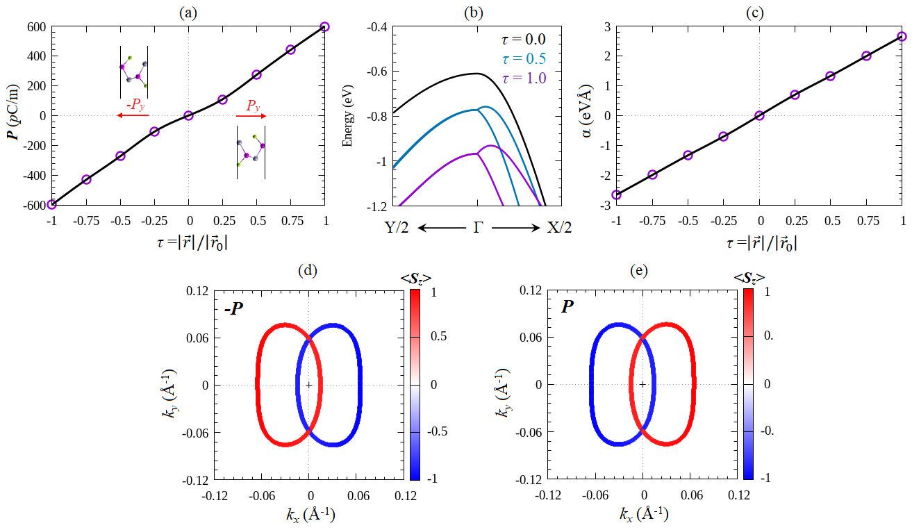
Before summarizing, we highlighted the interplay between the in-plane ferroelectricity, spin splitting, and the spin textures in the Ga ML compounds. Fig. 5(a) displayed the in-plane electric polarization as a function of the ferroelectric distortion, . Here, is defined as the magnitude of the distortion vector of the systems defined by Eq. (1), which is normalized by the magnitude of the distortion vector of the optimized ferroelectric phase, . Therefore, represents the paraelectric phase, while shows the optimized ferroelectric phase as shown by the insert of Fig. 5(a). We can see that it is possible to manipulate the in-plane electric polarization by distorting the atomic position [see Fig. 1(a)]. The dependence of the in-plane polarization on the ferroelectric distortion sensitively affects the spin-split bands at the VBM around the point as shown in Fig. 5(b). It is found that the splitting energy and the position of the VBM around the point strongly depend on the ferroelectric distortion, i.e., a decrease in substantially reduces the spin splitting energy while the position of the VBVM shifts up to be higher in energy around the point. Accordingly, the significant change of the SOC strength is achieved, in which a linear trend of as a function of is observed as shown in Fig. 5(c). Importantly, our results also show that the SOC strength changes sign when the direction of the in-plane ferroelectric polarization is switched, resulting in a full reversal of the out-of-plane spin textures shown in Figs. 5(d)-(e). Such reversible spin textures are agreed well with our symmetry analysis given by Eq. (15), putting forward Ga ML compounds as a candidate of the FER class of 2D materials exhibiting the PST, which is useful for efficient and non-volatile spintronic devices.
IV CONCLUSION
In summary, we have investigated the emergence of the FRE in Ga (= Se, Te; = Cl, Br, I) ML compounds, a new class of 2D materials having in-plane ferroelectricity, by performing first-principles density-functional theory calculations supplemented with analysis. We found that due to the large in-plane ferroelectric polarization, a giant unidirectional out-of-plane Rashba effect is observed in the spin-split bands around the VBM, exhibiting the unidirectional out-of-plane spin polarization persisting in the entirely FBZ. These persistent spin textures can host a long-lived persistent spin helix modeBernevig et al. (2006); Altmann et al. (2014); Schliemann (2017), characterized by the large SOC strength and a substantially small wavelength of the helical spin polarization. Importantly, we observed fully reversible spin textures, which are achieved by switching the direction of the in-plane ferroelectric polarization, thus offering a possible application of the present system for efficient and non-volatile spintronic devices operating at room temperature.
The reversible unidirectional out-of-plane Rashba effect found in the present study is solely enforced by the in-plane ferroelectricity and the non-symmorphic space group symmetry of the crystal. Therefore, it is expected that this effect can also be achieved on other 2D materials having similar crystal symmetry. Recently, there are numerous 2D materials that are predicted to have space group symmetry such as the 2D elemental group V (As, Sb, and Bi) MLsPan and Zhou (2020); Xiao et al. (2018). Due to the stronger SOC in these materials, the better resolution of the unidirectional out-of-plane Rashba effect is expected to be observed. Therefore, our prediction is expected to trigger further theoretical and experimental studies in order to find novel 2D ferroelectric systems supporting the unidirectional out-of-plane Rashba effect, which is useful for future spintronic applications.
Acknowledgements.
This research was partly supported by RTA program (2021) supported by Universitas Gadjah Mada. Part of this research was supported by PDUPT (No.1684/UN1/DITLIT/DIT-LIT/PT/2021) and PD (No.2186/UN1/DITLIT/DIT-LIT/PT/2021) Research Grants funded by RISTEK-BRIN, Republic of Indonesia. The computation in this research was performed using the computer facilities at Universitas Gadjah Mada, Republic of Indonesia.References
- Manchon et al. (2015) A. Manchon, H. C. Koo, J. Nitta, S. M. Frolov, and R. A. Duine, Nat. Matter 14, 871 (2015).
- Varignon et al. (2018) J. Varignon, L. Vila, A. Barthélémy, and M. Bibes, Nature Physics 14, 322 (2018).
- Ganichev and Golub (2014) S. D. Ganichev and L. E. Golub, physica status solidi (b) 251, 1801 (2014).
- Rashba (1960) E. I. Rashba, Sov. Phys. Solid State 2, 1224 (1960).
- Dresselhaus (1955) G. Dresselhaus, Phys. Rev. 100, 580 (1955).
- Nitta et al. (1997) J. Nitta, T. Akazaki, H. Takayanagi, and T. Enoki, Phys. Rev. Lett. 78, 1335 (1997).
- Caviglia et al. (2010) A. D. Caviglia, M. Gabay, S. Gariglio, N. Reyren, C. Cancellieri, and J.-M. Triscone, Phys. Rev. Lett. 104, 126803 (2010).
- Koroteev et al. (2004) Y. M. Koroteev, G. Bihlmayer, J. E. Gayone, E. V. Chulkov, S. Blügel, P. M. Echenique, and P. Hofmann, Phys. Rev. Lett. 93, 046403 (2004).
- LaShell et al. (1996) S. LaShell, B. A. McDougall, and E. Jensen, Phys. Rev. Lett. 77, 3419 (1996).
- Zhuang et al. (2015) H. L. Zhuang, V. R. Cooper, H. Xu, P. Ganesh, R. G. Hennig, and P. R. C. Kent, Phys. Rev. B 92, 115302 (2015).
- Popović et al. (2015) Z. S. Popović, J. M. Kurdestany, and S. Satpathy, Phys. Rev. B 92, 035135 (2015).
- Absor et al. (2018) M. A. U. Absor, I. Santoso, Harsojo, K. Abraha, H. Kotaka, F. Ishii, and M. Saito, Phys. Rev. B 97, 205138 (2018).
- Affandi and Ulil Absor (2019) Y. Affandi and M. A. Ulil Absor, Physica E: Low-dimensional Systems and Nanostructures 114, 113611 (2019).
- Absor et al. (2017) M. A. U. Absor, I. Santoso, Harsojo, K. Abraha, H. Kotaka, F. Ishii, and M. Saito, Journal of Applied Physics 122, 153905 (2017), https://doi.org/10.1063/1.5008475 .
- Wang et al. (2007) W.-T. Wang, C. L. Wu, S. F. Tsay, M. H. Gau, I. Lo, H. F. Kao, D. J. Jang, J.-C. Chiang, M.-E. Lee, Y.-C. Chang, C.-N. Chen, and H. C. Hsueh, Applied Physics Letters 91, 082110 (2007), https://doi.org/10.1063/1.2775038 .
- Picozzi (2014) S. Picozzi, Frontiers in Physics 2, 10 (2014).
- Vedyayev et al. (2013) A. V. Vedyayev, M. S. Titova, N. V. Ryzhanova, M. Y. Zhuravlev, and E. Y. Tsymbal, Applied Physics Letters 103, 032406 (2013), https://doi.org/10.1063/1.4815866 .
- Matos-Abiague and Fabian (2015) A. Matos-Abiague and J. Fabian, Phys. Rev. Lett. 115, 056602 (2015).
- Di Sante et al. (2012) D. Di Sante, P. Barone, R. Bertacco, and S. Picozzi, Advanced Materials 25, 509 (2012).
- Liebmann et al. (2016) M. Liebmann, C. Rinaldi, D. Di Sante, J. Kellner, C. Pauly, R. N. Wang, J. E. Boschker, A. Giussani, S. Bertoli, M. Cantoni, L. Baldrati, M. Asa, I. Vobornik, G. Panaccione, D. Marchenko, J. Sánchez-Barriga, O. Rader, R. Calarco, S. Picozzi, R. Bertacco, and M. Morgenstern, Advanced Materials 28, 560 (2016).
- Rinaldi et al. (2018) C. Rinaldi, S. Varotto, M. Asa, J. Sławińska, J. Fujii, G. Vinai, S. Cecchi, D. Di Sante, R. Calarco, I. Vobornik, G. Panaccione, S. Picozzi, and R. Bertacco, Nano Letters 18, 2751 (2018).
- Stroppa et al. (2014) A. Stroppa, D. Di Sante, P. Barone, M. Bokdam, G. Kresse, C. Franchini, M.-H. Whangbo, and S. Picozzi, Nature Communications 5, 5900 (2014).
- Kepenekian et al. (2015) M. Kepenekian, R. Robles, C. Katan, D. Sapori, L. Pedesseau, and J. Even, ACS Nano 9, 11557 (2015).
- Narayan (2015) A. Narayan, Phys. Rev. B 92, 220101 (2015).
- Tao and Wang (2016) L. L. Tao and J. Wang, Journal of Applied Physics 120, 234101 (2016), https://doi.org/10.1063/1.4972198 .
- Tao et al. (2017) L. L. Tao, T. R. Paudel, A. A. Kovalev, and E. Y. Tsymbal, Phys. Rev. B 95, 245141 (2017).
- da Silveira et al. (2016) L. G. D. da Silveira, P. Barone, and S. Picozzi, Phys. Rev. B 93, 245159 (2016).
- Ahn (2020) E. C. Ahn, npj 2D Materials and Applications 4, 17 (2020).
- Han (2016) W. Han, APL Materials 4, 032401 (2016), https://doi.org/10.1063/1.4941712 .
- Junquera and Ghosez (2003) J. Junquera and P. Ghosez, Nature 422, 506 (2003).
- Gao et al. (2017) P. Gao, Z. Zhang, M. Li, R. Ishikawa, B. Feng, H.-J. Liu, Y.-L. Huang, N. Shibata, X. Ma, S. Chen, J. Zhang, K. Liu, E.-G. Wang, D. Yu, L. Liao, Y.-H. Chu, and Y. Ikuhara, Nature Communications 8, 15549 (2017).
- Zhou et al. (2018) W. Zhou, S. Guo, S. Zhang, Z. Zhu, X. Song, T. Niu, K. Zhang, X. Liu, Y. Zou, and H. Zeng, Nanoscale 10, 3350 (2018).
- Zhang and Liu (2018) S.-H. Zhang and B.-G. Liu, Nanoscale 10, 5990 (2018).
- Wu et al. (2019) W. Wu, Y. Jiao, S. Li, X.-L. Sheng, Z.-M. Yu, and S. A. Yang, Phys. Rev. Materials 3, 054203 (2019).
- Absor and Ishii (2021) M. A. U. Absor and F. Ishii, Phys. Rev. B 103, 045119 (2021).
- Ozaki (2003) T. Ozaki, Phys. Rev. B 67, 155108 (2003).
- Ozaki et al. (2009) T. Ozaki, H. Kino, J. Yu, M. J. Han, N. Kobayashi, M. Ohfuti, F. Ishii, T. Ohwaki, H. Weng, and K. Terakura, http://www.openmx-square.org/ (2009).
- Ozaki and Kino (2004) T. Ozaki and H. Kino, Phys. Rev. B 69, 195113 (2004).
- Ozaki and Kino (2005) T. Ozaki and H. Kino, Phys. Rev. B 72, 045121 (2005).
- Perdew et al. (1996) J. P. Perdew, K. Burke, and M. Ernzerhof, Phys. Rev. Lett. 77, 3865 (1996).
- Kohn and Sham (1965) W. Kohn and L. J. Sham, Phys. Rev. 140, A1133 (1965).
- Lejaeghere et al. (2016) K. Lejaeghere, G. Bihlmayer, T. Björkman, P. Blaha, S. Blügel, V. Blum, D. Caliste, I. E. Castelli, S. J. Clark, A. Dal Corso, S. de Gironcoli, T. Deutsch, J. K. Dewhurst, I. Di Marco, C. Draxl, M. Dułak, O. Eriksson, J. A. Flores-Livas, K. F. Garrity, L. Genovese, P. Giannozzi, M. Giantomassi, S. Goedecker, X. Gonze, O. Grånäs, E. K. U. Gross, A. Gulans, F. Gygi, D. R. Hamann, P. J. Hasnip, N. A. W. Holzwarth, D. Iuşan, D. B. Jochym, F. Jollet, D. Jones, G. Kresse, K. Koepernik, E. Küçükbenli, Y. O. Kvashnin, I. L. M. Locht, S. Lubeck, M. Marsman, N. Marzari, U. Nitzsche, L. Nordström, T. Ozaki, L. Paulatto, C. J. Pickard, W. Poelmans, M. I. J. Probert, K. Refson, M. Richter, G.-M. Rignanese, S. Saha, M. Scheffler, M. Schlipf, K. Schwarz, S. Sharma, F. Tavazza, P. Thunström, A. Tkatchenko, M. Torrent, D. Vanderbilt, M. J. van Setten, V. Van Speybroeck, J. M. Wills, J. R. Yates, G.-X. Zhang, and S. Cottenier, Science 351 (2016), 10.1126/science.aad3000.
- King-Smith and Vanderbilt (1993) R. D. King-Smith and D. Vanderbilt, Phys. Rev. B 47, 1651 (1993).
- Theurich and Hill (2001) G. Theurich and N. A. Hill, Phys. Rev. B 64, 073106 (2001).
- Kotaka et al. (2013) H. Kotaka, F. Ishii, and M. Saito, Japanese Journal of Applied Physics 52, 035204 (2013).
- Anshory and Absor (2020) M. Anshory and M. A. U. Absor, Physica E: Low-dimensional Systems and Nanostructures 124, 114372 (2020).
- Absor and Ishii (2019a) M. A. U. Absor and F. Ishii, Phys. Rev. B 100, 115104 (2019a).
- Absor and Ishii (2019b) M. A. U. Absor and F. Ishii, Phys. Rev. B 99, 075136 (2019b).
- Absor et al. (2020) M. A. U. Absor, I. Santoso, N. Yamaguchi, and F. Ishii, Phys. Rev. B 101, 155410 (2020).
- Absor et al. (2021) M. A. U. Absor, Y. Faishal, M. Anshory, I. Santoso, and F. Ishii, Journal of Physics: Condensed Matter 33, 305501 (2021).
- Kniep et al. (1983) R. Kniep, A. Wilms, and H. J. Beister, Materials Research Bulletin 18, 615 (1983).
- Kong et al. (2018) X. Kong, J. Deng, L. Li, Y. Liu, X. Ding, J. Sun, and J. Z. Liu, Phys. Rev. B 98, 184104 (2018).
- Liu et al. (2019) B. Liu, M. Niu, J. Fu, Z. Xi, M. Lei, and R. Quhe, Phys. Rev. Materials 3, 054002 (2019).
- Winkler et al. (2003) R. Winkler, S. Papadakis, E. De Poortere, and M. Shayegan, Spin-Orbit Coupling in Two-Dimensional Electron and Hole Systems (Springer, Berlin, 2003).
- Bernevig et al. (2006) B. A. Bernevig, J. Orenstein, and S.-C. Zhang, Phys. Rev. Lett. 97, 236601 (2006).
- Altmann et al. (2014) P. Altmann, M. P. Walser, C. Reichl, W. Wegscheider, and G. Salis, Phys. Rev. B 90, 201306 (2014).
- Schliemann (2017) J. Schliemann, Rev. Mod. Phys. 89, 011001 (2017).
- Kohda et al. (2012) M. Kohda, V. Lechner, Y. Kunihashi, T. Dollinger, P. Olbrich, C. Schönhuber, I. Caspers, V. Bel’kov, L. Golub, D. Weiss, et al., Physical Review B 86, 081306 (2012).
- Walser et al. (2012) M. Walser, C. Reichl, W. Wegscheider, and G. Salis, Nature Physics 8, 757 (2012).
- Koralek et al. (2009) J. D. Koralek, C. P. Weber, J. Orenstein, B. A. Bernevig, S.-C. Zhang, S. Mack, and D. Awschalom, Nature 458, 610 (2009).
- Dyakonov and Perel (1972) M. I. Dyakonov and V. I. Perel, Sov. Phys. Solid State 13, 3023 (1972).
- Kim et al. (2014) M. Kim, J. Im, A. J. Freeman, J. Ihm, and H. Jin, Proceedings of the National Academy of Sciences 111, 6900 (2014).
- Zhu et al. (2011) Z. Y. Zhu, Y. C. Cheng, and U. Schwingenschlögl, Phys. Rev. B 84, 153402 (2011).
- Yao et al. (2017) Q.-F. Yao, J. Cai, W.-Y. Tong, S.-J. Gong, J.-Q. Wang, X. Wan, C.-G. Duan, and J. H. Chu, Phys. Rev. B 95, 165401 (2017).
- Absor et al. (2016) M. A. U. Absor, H. Kotaka, F. Ishii, and M. Saito, Phys. Rev. B 94, 115131 (2016).
- Yaji et al. (2010) K. Yaji, Y. Ohtsubo, S. Hatta, H. Okuyama, K. Miyamoto, T. Okuda, A. Kimura, H. Namatame, M. Taniguchi, and T. Aruga, Nature Communications 1, 17 (2010).
- Lee et al. (2020) H. Lee, J. Im, and H. Jin, Applied Physics Letters 116, 022411 (2020).
- Li et al. (2019) X. Li, S. Zhang, H. Huang, L. Hu, F. Liu, and Q. Wang, Nano Letters 19, 6005 (2019).
- Ai et al. (2019) H. Ai, X. Ma, X. Shao, W. Li, and M. Zhao, Phys. Rev. Materials 3, 054407 (2019).
- Datta and Das (1990) S. Datta and B. Das, Appl. Phys. Lett. 56, 665 (1990).
- Fiori et al. (2014) G. Fiori, F. Bonaccorso, G. Iannaccone, T. Palacios, D. Neumaier, A. Seabaugh, S. K. Banerjee, and L. Colombo, Nature Nanotechnology 9, 768 (2014).
- Pan and Zhou (2020) Y. Pan and J. Zhou, Phys. Rev. Applied 14, 014024 (2020).
- Xiao et al. (2018) C. Xiao, F. Wang, S. A. Yang, Y. Lu, Y. Feng, and S. Zhang, Advanced Functional Materials 28, 1707383 (2018).