Oscillatory rheotaxis of active droplets in microchannels
Abstract
Biological microswimmers are known to navigate upstream of an external flow (positive rheotaxis) in trajectories ranging from linear, spiral to oscillatory. Such rheotaxis stems from the interplay between the motion and complex shapes of the microswimmers, e.g. the chirality of the rotating flagella, the shear flow characteristics, and the hydrodynamic interaction with a confining surface. Here, we show that an isotropic, active droplet microswimmer exhibits a unique oscillatory rheotaxis in a microchannel despite its simple spherical geometry. The swimming velocity, orientation, and the chemical wake of the active droplet undergo periodic variations between the confining walls during the oscillatory navigation. Using a hydrodynamic model and concepts of dynamical systems, we demonstrate that the oscillatory rheotaxis of the active droplet emerges primarily from the interplay between the hydrodynamic interaction of the finite-sized microswimmer with all the microchannel walls, and the shear flow characteristics. Such oscillatory rheotactic behavior is different from the directed motion near a planar wall observed previously for artificial microswimmers in shear flows. Our results provide a realistic understanding of the behaviour of active particles in confined microflows, as will be encountered in majority of the applications like targeted drug delivery.
Introduction
Microorganisms navigate upstream of external flows in confined environments ranging from biological, like sperm cells in the reproductive tract Kantsler et al. (2014) and bacteria (e.g. E. coli) in the upper urinary tract Lane et al. (2005), to medical, like E. coli in catheters Figueroa-Morales et al. (2020). Classically, the locomotion of organisms in shear flows by continuous reorientation in response to changes in external velocity gradients is called rheotaxis Bretherton and Rothschild (1961). Microorganisms, like bacteria, exhibit positive rheotaxis, i.e. swim upstream, due to a combination of passive mechanisms stemming from the interplay between the complex shape and motion of the microorganisms, activity-induced hydrodynamic interaction with the confining surfaces in the vicinity, and the characteristics of the ambient flow Kaya and Koser (2012); Uppaluri et al. (2012); Fu et al. (2012); Figueroa-Morales et al. (2015); Junot et al. (2019); Mathijssen et al. (2019); Jing et al. (2020). Specifically for bacteria, the interaction of the intricately shaped (chirality), moving flagella with the shear flow plays a critical role in dictating the rheotactic trajectory Fu et al. (2012); Mathijssen et al. (2019); Jing et al. (2020). Note then that in the absence of asymmetrical and/or counter-rotating components, like flagella, most of the mechanisms for passive rheotaxis are inapplicable. Therefore, the rheotactic characteristics of artificial microswimmers, e.g. Janus particles and active droplets, cannot be predicted a priori solely based on the understanding of rheotaxis of biological microswimmers.
In recent years, the scientific community has begun to address the immense potential of artificial microswimmers in applications like targeted cargo delivery and water remediation Soler and Sánchez (2014); Gao and Wang (2014); Ren et al. (2017). In the majority of these applications, the artificial microswimmers are inevitably required to navigate external flows in confinements, i.e. to rheotax. Despite this fact, quantitative understanding of rheotaxis of artificial microswimmers is surprisingly limited. Only recently it was demonstrated that spherical Janus particles near a surface exhibit robust cross-stream migration at a definite orientation relative to a uniform shear flow Katuri et al. (2018); Uspal et al. (2015). Furthermore, the rheotactic characteristics of gold-platinum Janus rods was shown to depend on the interfacial gold/platinum length ratio Brosseau et al. (2019) and the shear flow strength Baker et al. (2019). An analysis of these few works reveals three things- one, the prevailing understanding of rheotaxis of artificial microswimmers is limited to their observed behaviour near a surface and not in a confinement where simultaneous interaction with multiple surfaces in presence of a non-uniform shear flow is possible; two, a physical understanding of the characteristics of the associated chemical trail for artificial microswimmers during rheotaxis is still lacking; and three, the present understanding is solely based on the behaviour of Janus particles, and exclude active droplets which are an important class of artificial microswimmers. Active droplets are essentially oil/aqueous droplets in aqueous/oil surfactant medium which are intrinsically symmetric, unlike Janus particles Maass et al. (2016); Izri et al. (2014). Active droplets spontaneously break the symmetry of the isotropic base state to self-propel using Marangoni stresses Morozov and Michelin (2019); Hokmabad et al. (2021). Hence, these are not only simpler to generate and manipulate compared to Janus particles, but are also biocompatible. All these features make active droplets the foremost candidate for majority of the envisioned applications for artificial microswimmers, specifically targeted drug delivery. Therefore, rheotaxis of active droplets in confinements in itself deserves a detailed study. Here, narrow channels are of particular interest, since this geometry applies to almost all conceivable problems in nature or technological application.
Here, we investigate the rheotaxis of active droplets in a non-uniform, Poiseuille type shear flow in a quasi-2D microchannel. We demonstrate that the active droplet swims upstream in a surprising, steady oscillatory trajectory despite its inherent spherical symmetry. As it oscillates upstream, the active droplet accelerates and decelerates, and continuously changes its swimming orientation in a periodic manner between the two confining walls perpendicular to the plane of oscillation. We also implement a fluorescent microscopy technique to reveal the physical characteristic of the chemical (filled micelle) trail of the active droplet during such oscillatory rheotaxis. Using a semi-analytical hydrodynamic model, we show that the hydrodynamic interaction of the finite-sized, pusher-type microswimmer with all the walls of the microchannel, along with the shear flow characteristics, dictate the essential features of the oscillatory rheotactic dynamics. The oscillatory rheotaxis of active droplets demonstrated here reveals a new paradigm for rheotaxis of artificial microswimmers, beyond the linear motion at a definite orientation to a uniform shear flow demonstrated so far Katuri et al. (2018); Baker et al. (2019); Ren et al. (2017). Furthermore, we believe that our understanding of this new rheotactic behaviour will aid in conceptualizing and designing practical applications like targeted drug delivery which involve navigation of microswimmers in confinements.
Results
Oscillatory rheotaxis of an active droplet
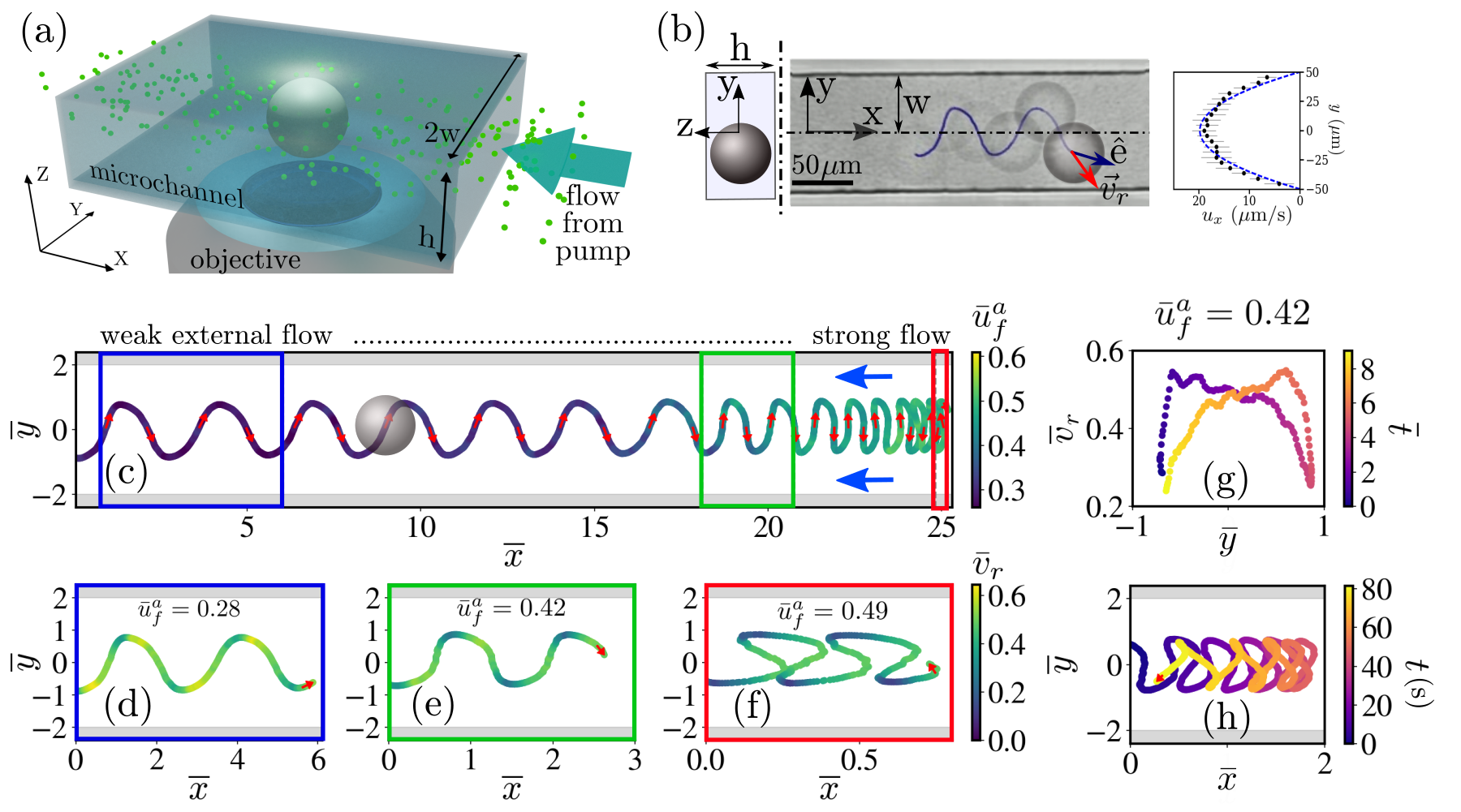
In this work, oil droplets (CB 15; dia. m) slowly dissolving in supramicellar aqueous solution of ionic surfactant (7.5 wt. aqueous solution of TTAB) comprise the active droplets. We observe the swimming behaviour of such self-propelling droplets in a quasi-2D microchannel (width ; height ) in presence of an external pressure-driven flow using bright field microscopy (Fig. 1a). The microchannel is fabricated from PDMS using photolithography and softlithography techniques, while the pressure-driven flow is actuated and maintained using a syringe pump. We study the swimming dynamics of the active droplet in the microchannel for different imposed flow rates (), represented here by the corresponding average flow velocity () in the X-Y plane (Fig. 1a). is evaluated using PIV analysis, for which the aqueous surfactant solution is seeded with tracer particles. The order of magnitude of the resultant shear is s-1. The variations in the trajectory, rheotactic or translational velocity (i.e. the magnitude of the tracked velocity vector ), and the intrinsic orientation of the active droplet (defined by the orientation of the intrinsic swimming velocity vector ) in the external flow are extracted from the bright-field microscopy images using in house Python code (see the Methods section for the experimental and the post-processing details). In the subsequent discussions, spatial variables are non-dimensionalized by (particularly, ), velocities by the intrinsic swimming speed of the active droplet in an unbounded quiescent medium, m/s, and times by . All such non-dimensionalized quantities are denoted by overbars.
It is worth noting first that in absence of the external flow, an active droplet self-propels in the quasi-2D microchannel following a linear trajectory while adhering to one of the side walls. On actuating the pressure-driven flow, an identical active droplet in the microchannel swims upstream in a novel oscillatory trajectory in the X-Y plane (Fig. 1b). With increasing , the active droplet exhibits persistent upstream oscillation, but the wavelength of the oscillatory trajectory gradually reduces (Fig. 1c). At a definite value of , the non-dimensional rheotactic velocity of the active droplet varies along the trajectory in a periodic manner (Fig. 1d-f). Specifically, reduces sharply as the droplet approaches a side wall (Fig. 1g). However, in the immediate vicinity of the side wall, the droplet accelerates and reaches its maximum value. Thereafter, gradually reduces as the droplet swims towards the opposite side wall while advancing upstream. Eventually, the droplet again sharply decelerates after it crosses the channel center-line and approaches that wall. At moderately high value of , the droplet eventually fails to effectively swim upstream. Interestingly, it is possible to trap the oscillating droplet within a small region by judiciously tuning about a threshold value () (Fig. 1h). Finally, beyond , the active droplet drifts downstream in a swinging trajectory (Fig. 2).
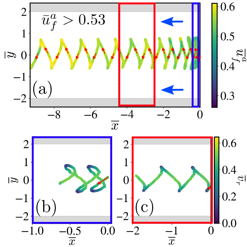
There are three things to be noted about the downstream drift of the active droplet. First, the active droplet drifts downstream for relatively smaller than 1, contrary to earlier theoretical works which predicted downstream drift of microswimmers for Zöttl and Stark (2012); Stark (2016). Second, the wavelength of the swinging drift trajectory increases with increasing (Fig. 2a), which is opposite to the trend observed during the oscillatory upstream rheotaxis (Fig. 1c). Finally, third, the periodic variation in over the swinging downstream trajectory remains qualitatively similar to that observed during upstream oscillation (Fig. 2b-c).
Variations in the intrinsic and translational orientations of the active droplet
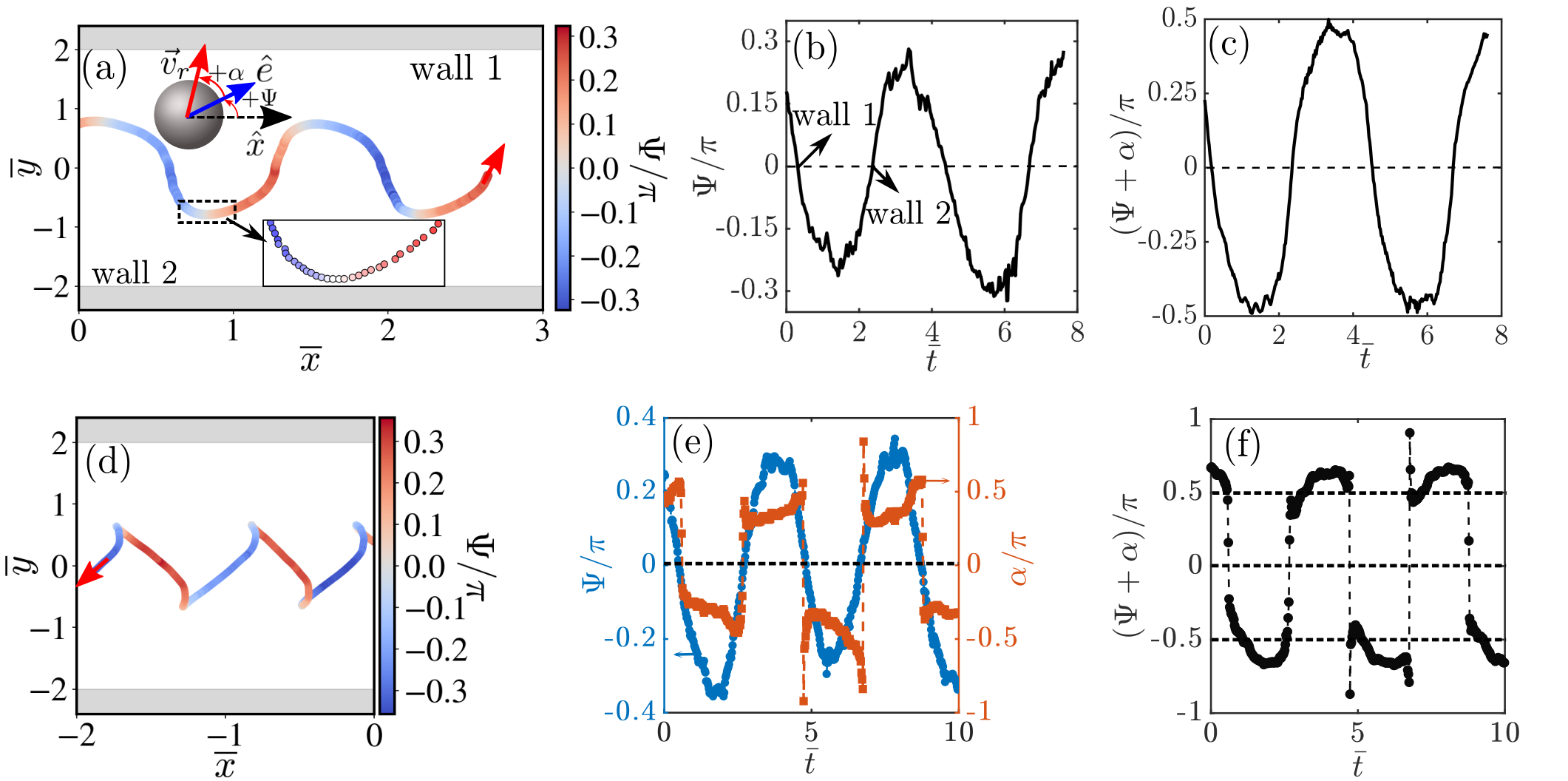
To further quantify the oscillatory rheotactic characteristics, we extract the variation in the intrinsic orientation of the active droplet. This is shown here by the variation in the angle which defines the orientation of the unit vector relative to in the X-Y plane (schematic in Fig. 3a). Here, , and is positive (negative) when measured in an anti-clockwise (clockwise) sense from (schematic in Fig. 3a). varies in a periodic manner over the oscillatory rheotactic trajectory (Fig. 3a). As the active droplet approaches a side wall with sharply decreasing (Fig. 1g), it continuously orients itself to become parallel to that wall ( reduces; Fig. 3a, b). Eventually, the droplet microswimmer becomes parallel to the wall () in its immediate vicinity for a brief period (residence time at ; Fig. 3a inset, b). Subsequently, as the droplet accelerates (Fig. 1g), it simultaneously orients away from the adjacent wall and towards the opposite side wall ( increases; Fig. 3a, b). Even when the droplet decelerates (Fig. 1g), it continues to orient itself towards the opposite wall, and crosses the channel center-line with the maximum cross-stream orientation (Fig. 3b). Thereafter, the droplet begins to approach the other wall with decreasing as before (Fig. 3b).
Note that the direction of cross-stream migration of the active droplet is different from its intrinsic orientation. This is expressed here by additionally defining an offset angle between and (schematic in Fig. 3a). The variation in the translational direction relative to is then given by the angle (Fig. 3c). varies smoothly about in the vicinity of the side walls (Fig. 3c). This implies that the translational orientation of the active droplet becomes truly parallel to the side walls in their immediate vicinity, and the droplet does not crash into the side walls during the oscillatory upstream rheotaxis.
We also evaluate the variations in the intrinsic and translational orientations of the active droplet during the swinging downstream drift (Fig. 3d-f). Interestingly, the droplet microswimmer always remains oriented upstream even as it moves downstream (Fig. 3d, e). However, for , the resulting velocity field makes orient downstream as the droplet traverses the width of the microconfinement (Fig. 3f). Note that while varies smoothly even during the downstream motion, undergoes sharp variations near the side walls (Fig. 3e). The latter is reflected in the variation of (Fig. 3f), and facilitates the downstream motion of the active droplet. In essence, it can be concluded that the active droplet does not self-propel or swim downstream, but it is pushed downstream in a swinging trajectory for .
Orientation of the chemical field of the active droplet during oscillatory rheotaxis
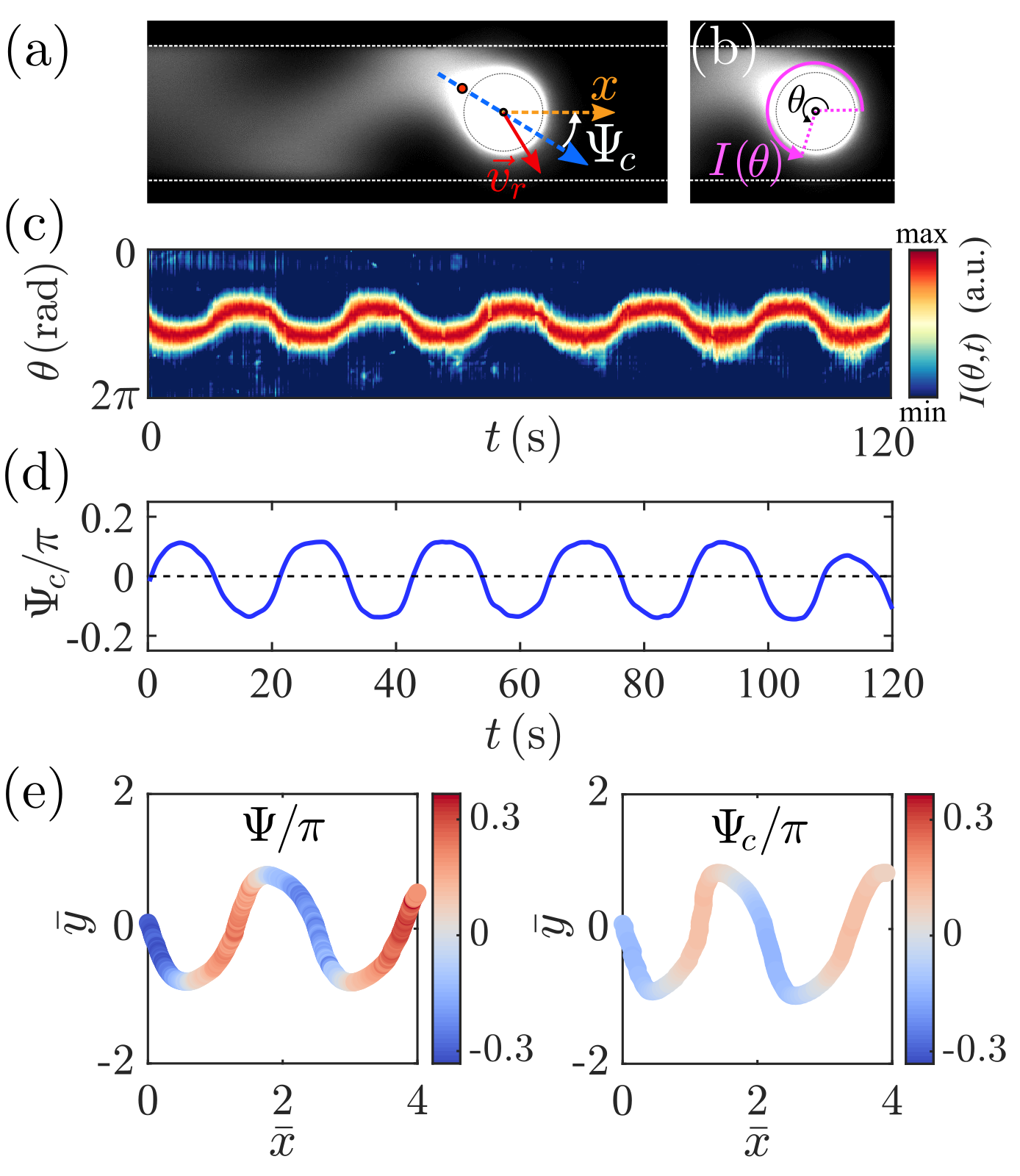
Based on our previous work on the motility of active droplets, we know that the chemical (filled micelle) field generated by the active droplet can locally interact with it altering the resulting orientation Hokmabad et al. (2021). It is then only logical to wonder whether similar secondary chemical interactions play any role in the above described rheotactic dynamics of the active droplet. To this end, we implement a fluorescence microscopy technique to visualize the filled micelle trail of the active droplet during the oscillatory upstream rheotaxis (Fig. 4a; see Methods section for details). Additionally, this endeavour also provides insight about the behaviour of the chemical trail during rheotaxis of artificial microswimmers in general; an aspect which has not been probed before.
We extract the fluorescence intensity profile emitted by the filled micelle field in the vicinity of the droplet interface over time (Fig. 4b), and map it onto a kymograph (Fig. 4c). The kymograph (Fig. 4c) shows that the orientation of the filled micelle trail of the droplet also follows a periodic variation during the oscillatory upstream rheotaxis. To quantify this orientational variation of the filled micelle tail, we define an angle which is supplementary to the extracted orientation angle of relative to (i.e. ; Fig. 4a). Fig. 4d quantitatively shows the periodic variation of the orientation of the filled micelle trail during the oscillatory rheotaxis. Here, we assume that the location of approximately coincides with the location of the maximum filled micelle concentration, which is at the posterior stagnation point (albeit in the droplet reference frame) Hokmabad et al. (2021). Therefore, under quiescent conditions, the swimming orientation and the ‘chemical angle’ are constant and identical, , as the orientation of the active droplet coincides with the anterior stagnation point. Therefore, for the present scenario, any offset between the variations in and will give an indirect measure of the distortion of the filled micelle tail orientation due to the resulting flow field during rheotaxis within the microconfinement; such distortions can trigger changes in the intrinsic swimming orientation Hokmabad et al. (2021). However, a comparison between and over the rheotactic trajectory (Fig. 4e) shows that these are satisfactorily similar. Therefore, it can be concluded that the filled micelle trail is not significantly distorted by the resulting velocity field. Accordingly, it is safe to assume that the filled micelle field does not additionally interfere with the rheotactic dynamics via local chemical interactions.
Understanding the oscillatory rheotaxis based on hydrodynamic interaction
To understand the essential features of the novel oscillatory rheotaxis of the active droplet we develop a simplified, approximate hydrodynamic model. This endeavour stems from the understanding that for an axisymmetric, spherical microswimmer devoid of any chiral and/or counter-rotating components, like the active droplet, the mechanism for passive rheotaxis will likely stem from the interplay of the long-range hydrodynamic interaction with the confining walls Spagnolie and Lauga (2012) and the change in swimming orientation due to the external shear flow (the Bretherton-Jeffery effect) Bretherton (1962). In our simplified model, we neglect the coupling between the chemical concentration distribution and the hydrodynamics for the active dropletde Blois et al. (2019). This to a certain extent is also justified by the conclusion that the filled micelle field does not interfere with the oscillatory dynamics. However, it is not obvious a priori to what extent a purely hydrodynamic model will be able to capture the oscillatory rheotactic dynamics.
We describe the droplet microswimmer by an equivalent squirmer model comprising of a superposition of a force dipole (‘fd’), a source dipole (‘sd’), and a source quadrupole (‘sq’) de Blois et al. (2019); Kuron et al. (2019). Accordingly, the velocity field of the swimming droplet can be written as
Here, , , and are the strengths of the force dipole, source dipole, and the source quadrupole singularities respectively, is the position vector, and is the location of the squirmer. Subsequently, we use the method of images Spagnolie and Lauga (2012); Kuron et al. (2019); de Blois et al. (2019); de Graaf et al. (2016) to evaluate the velocity field resulting from the hydrodynamic interaction of the squirmer with all the four walls of the quasi-2D microchannel i.e. the two side walls normal to the X-Y plane, and the top and bottom walls parallel to the X-Y plane. The total external velocity field can be then written as
| (1) |
Here, represents the velocity field due to the image system at a wall corresponding to a particular singularity, is the location of the image singularities for a particular wall, represents the vector sum of for all the walls, is the imposed pressure-driven velocity field, and . is approximated here as a plane Poiseuille flow in the X-Y plane in accordance with the experimental observation (Fig. 1b). Furthermore, there are two additional approximations involved here. First, Eq. (1) is a far-field approximation, and hence ignores that the droplet radius and wall distance are of similar order. Second, is approximate to the leading order as we consider a total of twelve image systems - images for force dipole, source dipole, and source quadrupole singularities at each of the four walls, instead of the infinite series of images that should be considered to satisfy the no-slip boundary condition at the walls Mathijssen et al. (2016).
We use Faxen’s first law for a force-free sphere Leal (2007); Kuron et al. (2019); Spagnolie and Lauga (2012) to evaluate the translational velocity of the squirmer in response to . Accordingly, the x- and y- components of the translational (rheotactic) velocity can be evaluated as
| (2) |
| (3) |
Here, each of the terms with represent two terms due to the image system at the two side walls; the first and second signs represent the contribution from the image systems at wall 2 and wall 1 respectively (Fig. 3a). The constant represents the total and only contribution from the image systems at the top and bottom walls. Finally, the temporal change in the intrinsic swimming orientation of the squirmer is given by where is the angular velocity of the squirmer according to Faxen’s second law for a torque-free sphere Spagnolie and Lauga (2012); Kuron et al. (2019). Following this, the rate of change of the swimming orientation can be evaluated as
| (4) |
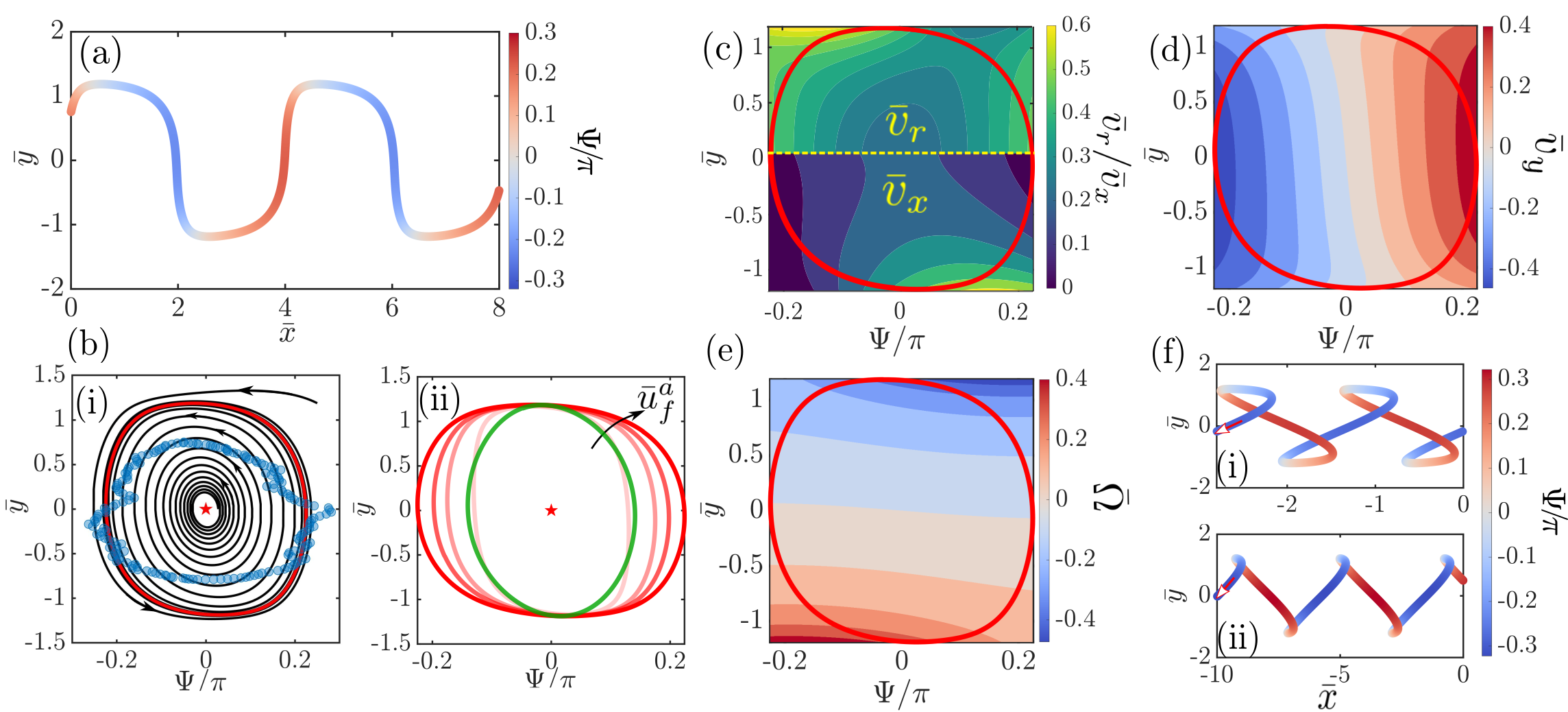
Eqs. (3) and (4) form a coupled system of equations, which is solved numerically for and . Thereafter, Eq. (2) is numerically integrated to evaluate the corresponding . Fig. 5a shows the trajectory of the squirmer colour-coded by for , as obtained from Eqs. (2)-(4). A comparison with Fig. 3a shows that the hydrodynamic model indeed satisfactorily captures the oscillatory rheotaxis of the active droplet (for , , and ). For a better understanding, we plot the rheotactic dynamics in the - phase space.
Phase portraits
The steady upstream oscillation of the active droplet represents a stable limit cycle in the - phase space (Fig. 5b(i); solid red line: theory; transparent blue markers: experiment). Note that perfect upstream orientation at the microconfinement centerline (; star marker in Fig. 5b(i)) represents an unstable fixed point. With increasing , the active droplet undergoes the self-sustaining upstream oscillation with sharper changes in over (Fig. 5b(ii)). This stems from the increase in droplet angular velocity with increasing angular velocity (vorticity) of the background flow, due to the one-to-one relationship between the two quantities following Faxen’s second law. Additionally, reduces with increasing (see Eq. (2)). The increase in and the simultaneous decrease in culminate in the reducing oscillation wavelength with increasing (Fig. 1c). Before proceeding further, it is important to note here that the finite size of the active droplet relative to the microchannel, as embodied by , plays a pivotal role in the observed rheotactic dynamics. Due to its finite radius, the droplet consistently turns away from the side walls of the microchannel faster (higher ) resulting in enhanced variation in (compare the opaque red and green solid lines in Fig. 5b(ii)). Furthermore, comparable and allows the top and bottom walls to alter the rheotactic dynamics by significantly reducing (see Eqs. (2) and (3)). We can conclude that while it is theoretically possible to model the oscillatory rheotaxis of a microswimmer by ignoring the aforementioned finite size effects, these observations will be aphysical, and inconsistent with the experimentally observed variations in and .
The variation of along the oscillatory trajectory obtained using Eqs. (2)-(4) (top half of Fig. 5c) is also similar to the experimentally observed variation (Fig. 1e, g). For a particular , as the active droplet approaches a side wall, the high (Fig. 5e) due to its finite size (consequence of the source dipole) results in strong reorientation away from the wall. This weakens the effect of the pusher-like droplet’s attraction towards the approaching wall (the consequence of the force dipole). Consequently, the increase in (bottom half of Fig. 5c) is weaker compared to the decrease in (Fig. 5d) in the direction of the approaching wall. Such relative variations of and , and the enhanced magnitude of , manifest in the sharp reductions in (Fig. 1g) and (Fig. 3a, b) during the approach towards a side wall. However, in the immediate vicinity of a side wall, as and approach zero, the wall-induced sliding of the pusher-like droplet momentarily prevails resulting in a sharp increase in (bottom half of Fig. 5c). This culminates in the high acceleration of the droplet adjacent to the wall (Fig. 1g). Eventually, the strong orients the droplet towards the the opposite side wall with increasing and (Fig. 5d). However, during this part of the journey, the consequential reduction in (bottom half of Fig. 5c) dominates, resulting in a gradual decrease in (Fig. 1g). The aforementioned dynamics repeats itself once the droplet crosses the microchannel centerline, and approaches the opposite side wall.
Finally, Eqs. (2)-(4) also describe the downstream drift of the active droplet for (compare Fig. 5f and Fig. 2). The hydrodynamic model satisfactorily recreates the two main features of the swinging downstream drift- the active droplet always remains oriented upstream, and the wavelength of the swinging trajectory increases with increasing (Fig. 5f). The consistent inclusion of the full hydrodynamic interaction of the finite-sized microswimmer with all the confinig walls, while estimating and , results in the recreation of the downstream drift for . This is because now becomes negative for a relatively smaller value of due to the presence of the wall-induced hydrodynamic effects. We also conclude that the theoretical model can be used to address the hydrodynamic trapping of the active droplet (Fig. 1h) by tuning such that is strong and simultaneously varies about .
Discussion
In this study, we have investigated in experiment and theory a problem common in nature and artificial microswimmers, e.g. lab-on-a-chip applications: robust positive rheotaxis in microchannels under external flow. We first document a novel oscillatory upstream rheotaxis in microchannels for artificial swimmers (active droplets). Although this type of oscillatory rheotaxis has been observed for bioswimmers like E. coli Mathijssen et al. (2019) and T. brucei Uppaluri et al. (2012), it has not been evidenced before for artificial microswimmers. We demonstrate that the oscillatory rheotaxis of the active droplets can be physically captured by following a purely hydrodynamic approach of mapping our droplets on an ideal squirmer with a finite size, and then consistently accounting for its hydrodynamic interaction with the confining walls and the imposed shear flow. We achieve good quantitative agreement between experiment and theory even under the approximations of ignoring the chemical interactions and truncating the hydrodynamic images systems to the leading order for the walls of the microchannel. Using phase portraits, we illustrate that this model features a robust limit cycle, as also demonstrated by the striking regularity and reproducibility of our recorded trajectories. It will be interesting to investigate in future studies whether the inclusion of both phoretic and hydrodynamic interactions for the model microswimmer in the confinement, as done very recently Choudhary et al. (2021), can bridge the remaining differences between experiment and our somewhat idealized model for the rheotaxis of artificial microswimmers - notably, the relative overestimation (underestimation) of the oscillation wavelength (angular velocity) during rheotaxis. We strongly believe that the understanding of this new rheotactic behaviour of artificial microswimmers, including the possibility of hydrodynamically trapping these, will open up wide possibilities in conceptualizing and designing practical micro-robotic applications like targeted drug delivery.
Methods
Fabrication of micro-confinements
For the production of CB15 droplets, we
fabricated microfluidic chips in-house, using
soft lithography techniques Qin et al. (2010), as follows: CAD photomasks were printed onto an emulsion
film in high-resolution (128 000 dpi) by a commercial
supplier (JD Photo-Tools). Next, the photoresist SU-8 3025
(MicroChem) was spin-coated onto a silicon
wafer (Si-Mat). A negative mold was
cured in the SU-8 by UV light
exposure through the photomask.
We then poured a poly(dimethyl siloxane) (PDMS), mixture (SYLGARD 184 Silicone Elastomer Kit, DowCorning) with 10:1 weight ratio of base
to cross-linker over the wafer and baked it for 2 hours at 75 ∘C.
For the droplet generation we used a glass slide as a coverslip for the channel, whereas for the microchannels used in the experiments we coated the glass with PDMS to have similar boundary conditions at all channel walls. To create an even PDMS surface, we placed the glass slide with liquid PDMS on top of it in a spin coater (Laurell, WS-650HZB-23NPPB) for 45 s at 500 rotations/min. Afterwards we baked it for 2 hours at 75 ∘C.
Finally both channel structure and glass slide were treeated with a partial pressure air plasma (Pico P100-8; Diener Electronic GmbH+Co. KG) for 30 s and then pressed together, bonding the two surfaces.
Production of monodisperse CB15 droplets
The walls of these microfluidic chips were chemically treated to hydrophilize the channels where aqueous surfactant solution flowed. We followed the recipe of Petit et al. Petit et al. (2016): First, the channel walls were oxidized by a 1:1 mixture of hydrogen peroxide solution (H2O2 at 30 wt%, Sigma-Aldrich) and hydrochloric acid (HCl at 37 wt%,
Sigma-Aldrich). The mixture was flushed through the channels
for 2 minutes. Then, the channel was rinsed by flushing
double distilled water for 30 s. Next, a 5 wt% solution of
the positive polyelectrolyte poly(diallyldimethylammonium
chloride) (PDADMAC, Sigma-Aldrich) was flushed for 2 minutes through the oxidized channel. The PDADMAC
binds to the activated channel walls by ionic interactions.
Finally, a 2 wt% solution of the negative polyelectrolyte
poly(sodium 4-styrenesulfonate) (PSS, Sigma-Aldrich) was
flushed for 2 minutes.
Once the chips were treated, we mounted syringes of oil and
0.1 wt% aqueous TTAB solution to a microprecision
syringe pump (NEM-B101-02B; Cetoni GmbH), connected
them to the two inlets of the microfluidic chip via Teflon
tubing, and tuned the flow speed
through the chip to reach the desired droplet diameter.
Once the production was monodisperse and at a steady state, droplets were
collected in a bath of 0.1 wt% TTAB solution.
Experimental protocol for visualizing the rheotactic behaviour of active droplets
To observe the activity of the droplets, we put them into a 7.5 w% aqueous TTAB solution. To visualize the flow, and for subsequent PIV analysis, tracer particles (FluoSpheresTM carboxylate, 0.5 m, red (580/605), Life Technologies Corporation) were added to the aqueous solution.
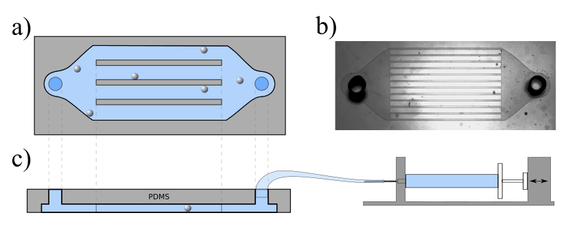
We observed the droplet motion in a quasi-two-dimensional channel structure with several parallel channels (Fig. 6), each of height and width of w = 100m. The flow inside the channels was controlled by a syringe pump connected via a Teflon tubing to the inlet of the channel structure. The outlet was left open and unconnected. We used an inverted bright-field microscope (Olympus IX-81) at a magnification of 20 for observation, and recorded videos at a frame rate of 25 frames per second with a Canon (EOS 600D) digital camera (19201080 px). Pixel-to-micrometre conversions were calibrated by imaging microstructures with known dimensions, including micrometre stages and channel structures.
Post-processing of experimental data
The droplet coordinates in each frame were extracted from video frames using software written in-house in Python/openCVBradski (2000), using a sequence of constant background correction, threshold binarization, blob detection by contour analysis, and minimum
enclosing circle fits. Swimming trajectories were obtained via a frame-by-frame nearest-neighbor analysisCrocker and Grier (1996).
We analyzed the flow in the aqueous swimming medium using the open source MATLAB package PIVlab
Thielicke and Stamhuis (2014), based on images extracted from videomicroscopy data with the open source software ffmpeg, and without any further preprocessing. For the calibration distance (inside PIVlab) the channel width was used with the defined width of 100m. For the analysis, a region of interest is chosen over the channel cross section and of around 60 m along the channel. Within PIVlab, the interrogation area was set specifically (Pass 1: 64, Pass 2: 32, Pass 3: 16, Pass 4: 8), with default settings kept otherwise.
Further calculations of the droplet speed, mean flow speed, etc. and plotting the figures were done with Python using mainly the libraries numpy and matplotlib.
Visualization of the chemical (filled micelle) trail during rheotaxis
We used fluorescent microscopy for direct imaging of the chemical trail secreted by the droplet Hokmabad et al. (2021, 2020). We doped the oil phase with the fluorescent dye NileRed (Thermo Fisher Scientific). The dye molecules co-migrate with the oil phase into the filled micelles shed by the droplet. Experiments were observed on an Olympus IX73 microscope with a filter cube (Excitation filter ET560/40x, Beam splitter 585 LP and Emissions filter ET630/75m, all by Chroma Technologies). Images were recorded using a 4 MegaPixels Grasshopper camera at 4 frames per second and magnification. Recorded images were analyzed, using MATLAB, to extract the red light intensity profiles () around the droplet close to the interface. We then identified the angular position of the maximum intensity point . The line from this point to the center of the droplet determines the orientation of the chemical field and in turn yields the ‘chemical angle’ .
Acknowledgements.
CCM, BVH and RD acknowledge funding from the DFG SPP 1726 “Microswimmers”, CCM and CJ from the BMBF/MPG MaxSynBio initiative. RD also acknowledges support from IIT Hyderabad.References
- Kantsler et al. (2014) V. Kantsler, J. Dunkel, M. Blayney, and R. E. Goldstein, “Rheotaxis facilitates upstream navigation of mammalian sperm cells,” Elife 3, e02403 (2014).
- Lane et al. (2005) M. C. Lane, V. Lockatell, G. Monterosso, D. Lamphier, J. Weinert, J. R. Hebel, D. E. Johnson, and H. L. Mobley, “Role of motility in the colonization of uropathogenic escherichia coli in the urinary tract,” Infection and immunity 73, 7644–7656 (2005).
- Figueroa-Morales et al. (2020) N. Figueroa-Morales, A. Rivera, R. Soto, A. Lindner, E. Altshuler, and É. Clément, “E. coli “super-contaminates” narrow ducts fostered by broad run-time distribution,” Science advances 6, eaay0155 (2020).
- Bretherton and Rothschild (1961) F. Bretherton and N. M. V. Rothschild, “Rheotaxis of spermatozoa,” Proceedings of the Royal Society of London. Series B. Biological Sciences 153, 490–502 (1961).
- Kaya and Koser (2012) T. Kaya and H. Koser, “Direct upstream motility in escherichia coli,” Biophysical journal 102, 1514–1523 (2012).
- Uppaluri et al. (2012) S. Uppaluri, N. Heddergott, E. Stellamanns, S. Herminghaus, A. Zöttl, H. Stark, M. Engstler, and T. Pfohl, “Flow loading induces oscillatory trajectories in a bloodstream parasite,” Biophysical Journal 103, 1162–1169 (2012).
- Fu et al. (2012) H. C. Fu, T. R. Powers, R. Stocker, et al., “Bacterial rheotaxis,” Proceedings of the National Academy of Sciences 109, 4780–4785 (2012).
- Figueroa-Morales et al. (2015) N. Figueroa-Morales, G. L. Mino, A. Rivera, R. Caballero, E. Clément, E. Altshuler, and A. Lindner, “Living on the edge: transfer and traffic of e. coli in a confined flow,” Soft matter 11, 6284–6293 (2015).
- Junot et al. (2019) G. Junot, N. Figueroa-Morales, T. Darnige, A. Lindner, R. Soto, H. Auradou, and E. Clément, “Swimming bacteria in poiseuille flow: The quest for active bretherton-jeffery trajectories,” EPL (Europhysics Letters) 126, 44003 (2019).
- Mathijssen et al. (2019) A. J. Mathijssen, N. Figueroa-Morales, G. Junot, É. Clément, A. Lindner, and A. Zöttl, “Oscillatory surface rheotaxis of swimming e. coli bacteria,” Nature communications 10, 1–12 (2019).
- Jing et al. (2020) G. Jing, A. Zöttl, É. Clément, and A. Lindner, “Chirality-induced bacterial rheotaxis in bulk shear flows,” Science advances 6, eabb2012 (2020).
- Soler and Sánchez (2014) L. Soler and S. Sánchez, “Catalytic nanomotors for environmental monitoring and water remediation,” Nanoscale 6, 7175–7182 (2014).
- Gao and Wang (2014) W. Gao and J. Wang, “The environmental impact of micro/nanomachines: a review,” Acs Nano 8, 3170–3180 (2014).
- Ren et al. (2017) L. Ren, D. Zhou, Z. Mao, P. Xu, T. J. Huang, and T. E. Mallouk, “Rheotaxis of bimetallic micromotors driven by chemical–acoustic hybrid power,” ACS nano 11, 10591–10598 (2017).
- Katuri et al. (2018) J. Katuri, W. E. Uspal, J. Simmchen, A. Miguel-López, and S. Sánchez, “Cross-stream migration of active particles,” Science advances 4, eaao1755 (2018).
- Uspal et al. (2015) W. Uspal, M. N. Popescu, S. Dietrich, and M. Tasinkevych, “Rheotaxis of spherical active particles near a planar wall,” Soft Matter 11, 6613–6632 (2015).
- Brosseau et al. (2019) Q. Brosseau, F. B. Usabiaga, E. Lushi, Y. Wu, L. Ristroph, J. Zhang, M. Ward, and M. J. Shelley, “Relating rheotaxis and hydrodynamic actuation using asymmetric gold-platinum phoretic rods,” Physical review letters 123, 178004 (2019).
- Baker et al. (2019) R. Baker, J. E. Kauffman, A. Laskar, O. E. Shklyaev, M. Potomkin, L. Dominguez-Rubio, H. Shum, Y. Cruz-Rivera, I. S. Aranson, A. C. Balazs, et al., “Fight the flow: the role of shear in artificial rheotaxis for individual and collective motion,” Nanoscale 11, 10944–10951 (2019).
- Maass et al. (2016) C. C. Maass, C. Krüger, S. Herminghaus, and C. Bahr, “Swimming Droplets,” Annu. Rev. Condens. Matter Phys. 7, 171–193 (2016).
- Izri et al. (2014) Z. Izri, M. N. Van Der Linden, S. Michelin, and O. Dauchot, “Self-propulsion of pure water droplets by spontaneous marangoni-stress-driven motion,” Physical review letters 113, 248302 (2014).
- Morozov and Michelin (2019) M. Morozov and S. Michelin, “Nonlinear dynamics of a chemically-active drop: From steady to chaotic self-propulsion,” The Journal of chemical physics 150, 044110 (2019).
- Hokmabad et al. (2021) B. V. Hokmabad, R. Dey, M. Jalaal, D. Mohanty, M. Almukambetova, K. A. Baldwin, D. Lohse, and C. C. Maass, “Emergence of bimodal motility in active droplets,” Physical Review X 11, 011043 (2021).
- Zöttl and Stark (2012) A. Zöttl and H. Stark, “Nonlinear Dynamics of a Microswimmer in Poiseuille Flow,” Phys. Rev. Lett. 108, 218104 (2012).
- Stark (2016) H. Stark, “Swimming in external fields,” The European Physical Journal Special Topics 225, 2369–2387 (2016).
- Spagnolie and Lauga (2012) S. E. Spagnolie and E. Lauga, “Hydrodynamics of self-propulsion near a boundary: Predictions and accuracy of far-field approximations,” Journal of Fluid Mechanics 700, 105–147 (2012).
- Bretherton (1962) F. P. Bretherton, “The motion of rigid particles in a shear flow at low reynolds number,” Journal of Fluid Mechanics 14, 284–304 (1962).
- de Blois et al. (2019) C. de Blois, M. Reyssat, S. Michelin, and O. Dauchot, “Flow field around a confined active droplet,” Physical Review Fluids 4, 054001 (2019).
- Kuron et al. (2019) M. Kuron, P. Stärk, C. Holm, and J. De Graaf, “Hydrodynamic mobility reversal of squirmers near flat and curved surfaces,” Soft matter 15, 5908–5920 (2019).
- de Graaf et al. (2016) J. de Graaf, A. J. Mathijssen, M. Fabritius, H. Menke, C. Holm, and T. N. Shendruk, “Understanding the onset of oscillatory swimming in microchannels,” Soft Matter 12, 4704–4708 (2016).
- Mathijssen et al. (2016) A. J. Mathijssen, A. Doostmohammadi, J. M. Yeomans, and T. N. Shendruk, “Hydrodynamics of micro-swimmers in films,” Journal of Fluid Mechanics 806, 35–70 (2016).
- Leal (2007) L. G. Leal, Advanced Transport Phenomena: Fluid Mechanics and Convective Transport Processes, Cambridge Series in Chemical Engineering (Cambridge University Press, Cambridge, 2007).
- Choudhary et al. (2021) A. Choudhary, K. Chaithanya, S. Michelin, and S. Pushpavanam, “Self-propulsion in 2d confinement: Phoretic and hydrodynamic interactions,” arXiv preprint arXiv:2104.00930 (2021).
- Qin et al. (2010) D. Qin, Y. Xia, and G. M. Whitesides, “Soft lithography for micro- and nanoscale patterning,” Nature Protocols 5, 491–502 (2010).
- Petit et al. (2016) J. Petit, I. Polenz, J.-C. Baret, S. Herminghaus, and O. Bäumchen, “Vesicles-on-a-chip: A universal microfluidic platform for the assembly of liposomes and polymersomes,” European Physical Journal E 39, 59 (2016).
- Bradski (2000) G. Bradski, “The OpenCV Library,” Dr Dobbs J. Softw. Tools 25, 120–125 (2000).
- Crocker and Grier (1996) J. C. Crocker and D. G. Grier, “Methods of digital video microscopy for colloidal studies,” Journal of Colloid and Interface Science 179, 298–310 (1996).
- Thielicke and Stamhuis (2014) W. Thielicke and E. Stamhuis, “PIVlab – Towards User-friendly, Affordable and Accurate Digital Particle Image Velocimetry in MATLAB,” Journal of Open Research Software 2, e30 (2014).
- Hokmabad et al. (2020) B. V. Hokmabad, S. Saha, J. Agudo-Canalejo, R. Golestanian, and C. C. Maass, “Quantitative characterization of chemorepulsive alignment-induced interactions in active emulsions,” arXiv , 2012.05170 (2020).