Influence of the bus waveguide on the linear and nonlinear response of a taiji microresonator
Abstract
We study the linear and nonlinear response of a unidirectional reflector where a nonlinear breaking of the Lorentz reciprocity is observed. The device under test consists of a racetrack microresonator, with an embedded S-shaped waveguide, coupled to an external bus waveguide (BW). This geometry of the microresonator, known as “taiji” microresonator (TJMR), allows to selectively couple counter-propagating modes depending on the propagation direction of the incident light and, at the nonlinear level, leads to an effective breaking of Lorentz reciprocity. Here, we show that a full description of the device needs to consider also the role of the BW, which introduces (i) Fabry-Perot oscillations (FPOs) due to reflections at its facets, and (ii) asymmetric losses, which depend on the actual position of the TJMR. At sufficiently low powers the asymmetric loss does not affect the unidirectional behavior, but the FP interference fringes can cancel the effect of the S-shaped waveguide. However, at high input power, both the asymmetric loss and the FPOs contribute to the redistribution of the energy between the clockwise and counterclockwise modes within the TJMR. This strongly modifies the nonlinear response, giving rise to counter-intuitive features where, due to the FP effect and the asymmetric losses, the BW properties can determine the violation of the Lorentz reciprocity and, in particular, the difference between the transmittance in the two directions of excitation. The experimental results are explained by using an analytical model based on the transfer matrix approach, a numerical finite-element model and exploiting intuitive interference diagrams.
I Introduction
In the last decade, several efforts have been spent to implement optical circuits which show different behavior depending on the propagation direction of the incident light [1, 2, 3, 4, 5, 6, 7, 8, 9, 10, 11, 12, 13, 14, 15, 16, 17, 18, 19, 20]. The realization of an integrated system capable of working as an optical isolator in the linear regime is prohibited by the Lorentz reciprocity theorem [21, 22]. This ensures that transmission through any linear and non-magnetic media does not depend on the direction of propagation. However, by properly engineering the optical system, it is possible to induce a non-Hermitian behavior and obtain direction-dependent properties [23, 24, 25]. A widely exploited non-Hermitian system is a racetrack microresonator with an embedded S-shaped waveguide (taiji microresonator, TJMR). The TJMR with a gain medium has been studied to achieve unidirectional behaviour in semiconductor ring laser devices [16, 17, 18] and, recently, in topological lasers [19, 26]. In [25], we studied the unidirectional reflector behaviour of TJMR. When a TJMR is coupled to a bus waveguide (BW), the transmission in both excitation directions is the same while the reflection can assume completely different values. Moreover, such a non-Hermitian design can be combined with the nonlinear material response to break the Lorentz reciprocity theorem, as was demonstrated in [8]. There, the breaking of the reciprocity is observed in both a direction-dependent nonlinear shift of the TJMR resonances as well as in a direction-dependent optical bistability loop. These results are strictly related to the role of the S-shaped waveguide which allows to selectively couple the counter-propagating modes in a direction-dependent way. Therefore, the energy stored within the TJMR shows different values for the different excitation directions.
While the experiments in [8] were restricted to the simplest configurations and provided a pioneering understanding on the basic effect, here we proceed in our analysis by investigating in full detail the role of the BW in this physics. In fact, the reflections at the BW facets[27, 28] and the BW propagation losses cause a redistribution of the internal energy in the TJMR which depends on the actual position of the microresonator along the waveguide. In particular, we report a joint experimental and theoretical study of the interference of the BW optical mode with the clockwise (CW) and counterclockwise (CCW) TJMR modes. We discuss the response of the system in the linear and nonlinear regimes where the microresonator-position-dependent asymmetric propagation losses and the Fabry-Perot oscillations (FPOs) redistribute the internal energy between both modes yielding a direction-dependent response.
The structure of the paper is the following. In section II we report the experimental evidences of different transmission and reflection behaviors in the linear and nonlinear regimes. In section III we discuss the numerical simulations which reproduce the experimental observation. In section IV we draw the conclusions.
II Experiments
II.1 The device and the experimental setup
The BW/TJMR coupled system (the device in the following) is built on single mode channel waveguides made of a silicon oxynitride (SiON) film on a 6 inch Silicon wafer, see [25] for more details. The TJMR consists of a racetrack resonator with a S-shaped waveguide across, as shown in Fig. 1 (a). The tips of the S-shaped waveguide have a dark cavity shape to trap the propagating mode and, consequently, to avoid back-reflections [29]. The coupling between the waveguides is ensured by three directional couplers: one for the BW () and two for the S-shaped branch ( and ). The perimeter of the racetrack is defined as (see Fig. 1), while the length of the S-shaped waveguide is . The BW has two polished end facets where light is input or output by butt coupling tapered fibers. Its length is given by . and define the relative position of the TJMR along the BW. We measured two samples with equal TJMR parameters and while different and . More details on the device are reported in [25].
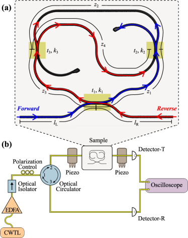
The experimental setup shown in Fig. 1 allows measuring the transmission and reflection spectra of the device. A continuous wave tunable laser (Yenista OPTICS, TUNICS-T100S) operating in the IR range ( - ) is fiber-coupled to an erbium doped fiber amplifier (IPG photonics). In order to prevent laser damage its emission passes through an isolator and the resulting signal is adjusted in polarization by means of a polarization control stage. After it, the light is coupled to a fiber-circulator, which sends the light into a lensed tapered fiber. The light is then butt-coupled to the device using a xyz piezo-positioner for a correct alignment. At the device output, another lensed tapered fiber collects the transmission response and sends the light into an InGaAs detector-T (Thorlabs, PDA20CS(-EC)). At the same time, the light, which is back-reflected by the device input facet, is filtered out by the circulator and it is acquired by another InGaAs detector-R (Thorlabs, PDA20CS2). The detector-T and detector-R signals are then measured simultaneously with an oscilloscope (PicoScope 4000 Series). We note that at high input powers, only the transmission spectra are measured because of the damage threshold of the optical circulator.
Turning the device on the sample holder, we input the light in either forward or in reverse configurations. In the forward configuration, light is CCW-coupled to the TJMR (see blue arrows in Fig. 1 (a)). Therefore, neglecting the FPOs due to reflections at the BW facets, the light circulates into the outer path and the S-shaped waveguide is just a source of losses. In this case only a finite transmittance is recorded. In the reverse configuration, light is CW-coupled to the TJMR and part of it is coupled into the CCW direction by means of the S-shaped waveguide (see red arrows in Fig. 1 (a)). Therefore, in this case, we do measure both finite transmission and reflection signals from the device. In the linear regime this leads to the unidirectional reflector behavior described in Ref. [25].
II.2 Experimental results in the linear regime
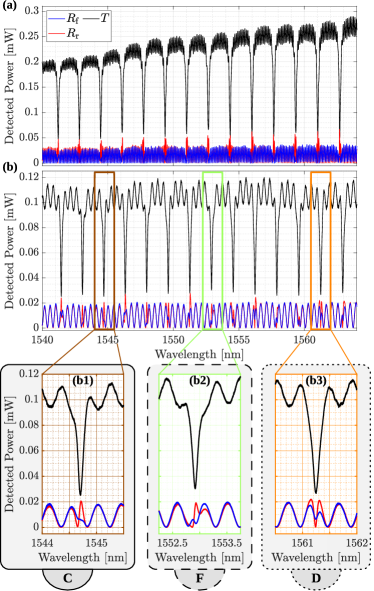
The transmission and reflection spectra of two devices with a different BW length are shown in Figure 2 for both forward and reverse configurations. Panel (a) refers to while panel (b) to . In agreement with the Lorentz reciprocity theorem, the transmission spectra for the forward and reverse configurations are the same. They display a set of resonance dips at the TJMR resonances within short FPOs due to the reflection at the input and output facets of the BW. Each resonance dip exhibits a typical Lorentzian shape and never shows a doublet as in the case of backscattering [30, 31]. This means that, in our case, the surface wall roughness is not a dominant source of intrinsic losses. Consequently, it does not contribute to the non-Hermitian dynamics induced by the presence of embedded S-shaped [25]. It is worth noting that out of resonance the two reflections overlaps perfectly. Therefore, the two bus waveguide facets contribute in the same fashion to the reflected component of the optical field. As expected, by decreasing the BW length, the number of resonances remains constant, while the FP period increases by about four times (see Fig. 2 (b)). In the forward orientation, this variation does not modify the reflection response of the device which shows the usual FP fringes (see blue curves of Fig. 2). On the other hand, the reflection in the reverse configuration drastically changes. Specifically, in panel (a) the reflected intensity always shows clear resonance peaks, while in panel (b) it strongly varies as a function of the incident wavelength. This is due to the fact that the short interference fringes of the long device do not affect the reflected optical mode from the TJMR while the long FP interference fringes in the short device cause significant interference between the taiji reflected mode and the BW modes. This interference may destroy the effect of the S-shaped waveguide in the device reflection. Specifically, as shown in the zoom of Fig. 2 (b), we observe three main cases: constructive-like (b1), Fano-like (b2) and destructive-like (b3) reflection lineshape. In the first case (denoted with the letter C), constructive interference generates a resonant peak and, therefore, the device behaves as the typical TJMR [25]. In the second case (denoted with the letter F), the interference gives rise to a sharp peak with the same height of the FPO. Interestingly, in the third case (denoted with the letter D), destructive interference rules out the resonant reflection peak. In this case, the efficiency of the taiji as an unidirectional reflection device is much reduced.
II.3 Experimental results in the nonlinear regime
The three interference cases described in II.2 affect also the nonlinear response of the device. As demonstrated in [8], the TJMR exhibits a higher internal power in the reverse than in the forward configuration. In fact, in the forward configuration, the light is partially lost at the end of the S-shaped waveguide. On the other hand, in the reverse one, the S-shaped branch couples light from the CW to the CCW mode increasing the stored energy. As a result, the transmission response of the device to strong fields shows a non-reciprocal behavior. Since the reflected intensity is strictly connected to the energy stored inside the taiji, the FP and the propagation losses of the BW strongly affect the nonlinearity-induced non-reciprocal response.
First, we studied the role of the FP. We measured the transmitted spectra for different input powers ().
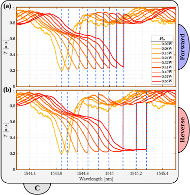
Figure 3 shows the transmission in forward (Fig. 3 (a)) and in reverse (Fig. 3 (b)) configurations for a resonance showing constructive-like feature in reflection in the linear regime. At low , the device exhibits the same resonance Lorentzian dips for both orientations. Increasing , the resonance is pushed towards longer wavelengths due to the build-up of the internal energy in the TJMR and the thermo-optic nonlinearity, see Appendix .3. Also, the lineshape changes and takes the typical triangular shape of a microresonator under strong pumping [32, 33, 34, 35]. To quantify these behavior we trace the resonance wavelength () as a function of . As the FPOs modify the wavelength at which transmittance reaches its minimum value, is measured as the wavelength position of the transmission dip at low , and as the threshold wavelength at which the transmittance switches to a value close to one after optical bistability [36, 37, 38, 32, 33, 39, 35, 40, 41] for the higher values of . Note that a large stored energy in the TJMR gives rise to a larger shift, as show in [8].
If we look at the experimental results and compare Figs. 3 (a) and (b), at sufficiently high , we note that the transmission spectra differ substantially. In particular, there is a wavelength interval where the two transmissions are no longer equal, i.e. where the Lorentz reciprocity is broken [8]. We quantify the extent of this wavelength region, by calculating the difference between the relative shift of for the reverse configuration and the forward configuration , i.e. between the “hot” and “cold” resonant wavelengths. vs is shown in Fig. 4 (a) together with representative comparisons between the normalized transmittance spectra at maximum for the forward and the reverse orientations (Fig. 4 (a1)-(a3)). In Fig. 4, the brown, green and orange colors refer to the different wavelength shifts for the constructive-like (C), Fano-like (F) and destructive-like (D) linear regime reflection lineshape, respectively.
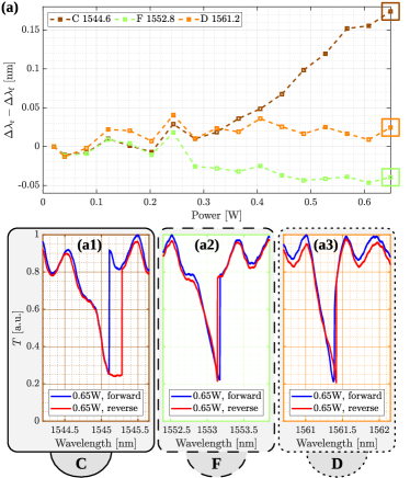
As already reported in [8], in the constructive-like case (blue symbols), is positive and, therefore, the reverse configuration shows a higher resonance shift (see Fig. 4 (a1)) for all . Since this shift is proportional to the power stored inside the cavity, the reverse configuration is characterized by a high internal energy. Similarly, the destructive-like case shows positive but small values (orange symbols and panel (a3) of Fig. 4). On the contrary, the Fano-like case exhibits a negative detuning which implies a higher internal energy in the forward than in the reverse configuration (see panel (a2) of Fig. 4). This means that reflectance in the BW facets could cancel the effect of the S-shaped waveguide.
III Theory and simulation
III.1 Linear regime
In order to confirm the role of the FPOs in the linear and nonlinear regimes, we performed numerical simulations of the device. These simulations were based on the theoretical model reported in [25]. Here, the whole system is modeled by using the transfer matrix method where the only source of back-reflection is given by the FP cavity generated by the end facets of the BW. The three directional couplers of Fig. 1 (a) are schematized by three reciprocal and lossless beamsplitters characterized by their transmission and coupling amplitudes (). The parameters used in these simulations are reported in Fig. 9 of Appendix .1 and were determined by the geometry of the device and by a fit of the transmission spectrum of Fig. 2 (b). A wavelength-dependent effective refractive index as in [25] was also used. Note that, for these simulations is fixed.
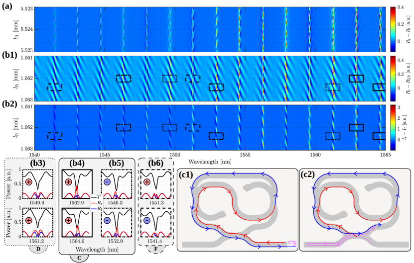
As we are interested in understanding the role of the FP fringes, we computed the device reflectivity for the reverse () and the forward () configurations and for the case without coupling between the BW and the TJMR (, as defined in Fig. 1 (a)). This last quantity describes the contribution to the reflectance of the device due to the FP in the BW and is labeled . Figure 5 (a) and (b1) show the vs maps of and of . A -range of around a value of (Fig. 5 (a)) and (Fig. 5 (b1)) is mapped. Since interference effects affect the internal energy () in the TJMR, we also plot in Fig. 5 (b2) the vs map of the difference between the internal energies in the reverse () and forward orientations () for the short device case. More details on the calculation of and are reported in Appendix .2. These various differences show the unidirectional behavior of the device and the role of the BW in this phenomenon. In particular, the clear lines that cut vertically through the maps represent the TJMR resonances. The colors reflect the different values of for each resonance. These take into account the spectral dispersion of the effective refractive index, of the propagation losses, of the coupling parameters and the dependence of the interference. For long (Fig. 5 (a)) the fact that always shows clear peaks is in agreement with the experimental data of Fig. 2 (a). For short (Fig. 5 (b1)), the decrease of the BW length allows catching all the experimental cases. These are highlighted by the rectangles in Fig. 5 (b1)-(b2). Specific examples of the simulated transmission and reflection lineshapes for the destructive-like (D), constructive-like (C) and Fano-like (F) cases are shown in Fig. 5 (b3), b(4)-b(5), and (b6), respectively, for (top) and (bottom).
Let us start from the destructive-like case. This is characterized by a dip of the reflectance in the reverse configuration (Fig. 2 (b3)). This case is exemplified by the dotted rectangles in panels (b1) and (b2) and by the lineshapes in (b3) of Fig. 5. The reflectance dip is a consequence of the interference between the light that is reflected at the input facet of the BW (magenta arrow) and the light that propagating in the CW mode (red arrows) is coupled into the CCW one through the S waveguide (blue arrows), as shown in the sketch of panel (c1). When such interference is destructive, the reflected intensity can exhibit a dip. The condition for interference in the device is:
| (1) |
where and are, respectively, the effective refractive index and an integer number.
Thus, the phase difference between the path followed by the light reflected from the TJMR (left hand of Eq. (1)) and the one followed by the light reflected from the input facet must be an odd multiple of . That is, when satisfies:
| (2) |
This condition is satisfied in the example shown in panel (b3, top), where the reflectance (red line) reduces to zero at the resonant wavelength. However, as shown in panel (b3, bottom), a slight shift of the FP fringes due to a slight variation in (from 1.0620 (top) to (bottom)) causes a different interference which yields a non-zero reflection. This interference pattern is also confirmed by the positive value of the internal energy difference shown in panel (b2), as evidenced by the dotted rectangle. Hence, less reflection of the device does not mean less internal energy in the reverse with respect to the forward configurations. This can be understood by considering two other interference diagrams. The first one is defined by the path followed by the light in the BW. It gives rise to the typical constructive FP interference at the exit of the input facet:
| (3) |
where is an integer number. The second is more complex and is shown in panel (c2) of Fig. 5. It is given by the constructive interference, inside the TJMR, between the light which is transferred from the S-shaped waveguide to the CCW mode (from red to blue arrows) and the one that is reflected from the output facet of the BW (magenta arrows). Defining as an integer number, this interference occurs when the following relation is satisfied:
| (4) |
These three numbers , and are strictly connected as:
| (5) |
If and are integer numbers, then also is an integer number. In other words, if the FP interference exhibits a peak and the device reflection shows a dip, then inside the TJMR occurs a constructive interference with a build up of internal energy ().
This analytical model also explains the constructive-like case shown in Fig. 2 (b1). The solid and dashed-dotted rectangles highlight regions characterized by a high reflection intensity (Fig. 5 (b1)) but different internal energies (Fig. 5 (b2)). Characteristic spectra are plotted in panel (b4) and (b5) for (top) and (bottom). In this case, the TJMR behaves as a unidirectional reflector. Therefore, the reflected intensity exhibits a maximum in the reverse configuration (red lines). The panel (b4) differs from panel (b5) because of the difference between the internal energy of the forward and reverse configurations. In the first, the stored energy is higher in the reverse orientation than in the forward one. In the second, a lower energy is found in the reverse than in the forward configuration. The difference between the two situations is due to the wavelength dependence of the propagation losses in the BW (Appendix .1), as we will discuss in the following.
Panel (b1) of Fig. 5 shows also the Fano-like case (see dashed rectangles) as highlighted by the graphs of panel (b6). This is an intermediate case between the constructive-like and the destructive-like cases.
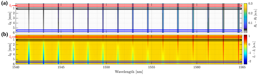
The TJMR loses its fundamental property of being a unidirectional reflector because of the FPOs. Simulating the response of the device in the absence of the FP (i.e with zero facets reflectivity), we obtain the vs maps in Fig. 6. Note that, for these simulations is fixed. In particular, Fig. 6 (a) shows while Fig. 6 (b) shows . The red, black, and blue rectangles highlight the regions around the values , , and , respectively, i.e. in the latter two the TJMR is not placed in a symmetric position with respect to the two BW facets. In contrast with Fig. 5, no oscillations are observed and at the resonances always since . Note that changes as varies. In fact, as increases, the BW propagation losses affect the amount of light coupled to the microresonator. Therefore, less energy is transferred from the CW to the CCW mode. As a function of (see the rectangles), the reflected intensity in the reverse configuration increases with the wavelength. This is due to the spectral dependence of the BW propagation losses, which are large at and decrease monotonically as increases (see Appendix .1). Also is affected by the relative position of the TJMR with respect to the BW. Indeed, by increasing more and more resonances present a negative . Moreover, this negative value becomes larger as decreases, i.e. as the losses increase.
To summarize the analysis of the linear regime, the interference between the reflected fields at the ends of the BW and by the TJMR generate different spectral responses. In particular, depending on the period of the FP fringes, the device may preserve or lose its unidirectional reflector nature. As a result, the difference between the internal energies in the reverse and forward configurations may assume both positive and negative values.
III.2 Nonlinear regime
The device is modelled in the nonlinear regime by following the finite-element model developed in Ref. [8]. The light propagation inside the device is obtained by solving the nonlinear Helmholtz equation while taking also into account reflection at the BW facets. We took the thermal nonlinearity parameters from [40]. The set of employed parameters is shown in Appendix .1 and .3.
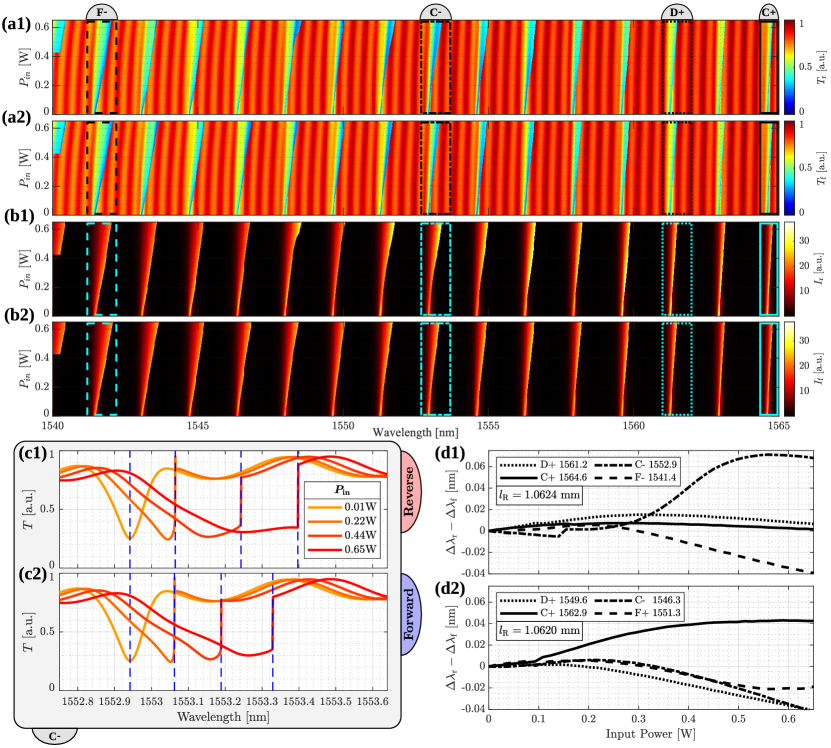
Figure 7 (a) and (b) show the transmission spectra and the TJMR internal energies as a function of the input power () for , while scanning from low to high values. Panels (a1) and (b1) display the reverse configuration while (a2) and (b2) show the forward one. As expected, increasing , the resonances shift proportionally to the internal energy due to the nonlinear refractive index. This shift is towards longer in agreement with the positive sign of the nonlinear coefficient (see Fig. 10 in Appendix .3). Notice that the FP fringes slightly shift to longer wavelengths too. The difference between the resonance and fringe shifts is explained by the larger energy stored in the microresonator than in the BW. In fact, a times field enhancement factor is computed for the TJMR. Within the maps, we can identify the different features seen in the experimental section, i.e. constructive-like (C), destructive-like (D) and Fano-like (F) shape. These are labelled with a + (-) when, in the linear regime, (). Figure 7 (c1) and (c2) are the theoretical analogue of Figure 3 (b) and (a), which show the experimental transmission spectra. Figure 7 (c1) and (c2) display the transmittance for different input powers in the C- case. The wavelength is scanned from low to high values. In particular, panel (c1) and (c2) show the reverse and forward orientations, respectively. The theoretical model reproduces the experimental behavior and Lorentz reciprocity breaking appears through a different resonance shift between forward and reverse orientation increasing the input power. Comparing the nonlinear shift for the forward and reverse orientations, we do not observe a regular trend. Fig. 7 (d1) shows as a function of , computed from the (a1)-(a2) maps. Specifically, the dotted, dash-dotted/solid and dashed lines highlight the destructive-like (D), constructive-like (C) and Fano-like (F) cases, respectively. These resonances are the ones shown in Fig. 5 (b3)-(b6) for the linear regime and (i.e. the bottom panels). It is observed that shows different behaviors in the three cases in agreement with the experimental results of Fig. 3. In fact, in both the experimental (labeled D in Fig. 4) and the theoretical case (labeled D+ in Fig. 7), the destructive-like case shows a positive value of slightly greater than zero. The same agreement holds for the experimental (C) and theoretical (C-) constructive-like cases where the detuning is always positive and reaches a maximum value around . Similarly for the Fano-like case, where both the theoretical (F-) and experimental (F) shift differences show negative values.
However, a clear relation between in the linear and nonlinear regimes does not emerge. In fact, in the constructive case, the vs curve shows both a positive slope for the C- situation, where in the linear regime, as well as an almost zero slope for the C+ situation where in the linear regime. This lack of a direct relation between in linear and nonlinear regimes is also shown in Fig. 7 (d2). It displays vs for the resonances shown on the top panels (b3)-(b6) of Fig. 5 (i.e. when ). Here, the destructive-like case (D+) presents a negative shift despite in the linear regime. In addition, the constructive-like case with (C-) exhibits a negative shift in contrast with Fig. 7 (d1). Therefore, depending on their spectral position, the resonances of the TJMR show a different shift which we attribute to the interplay between the FP and the asymmetric losses () in the BW.
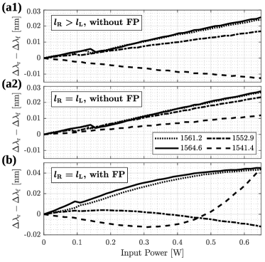
This is evidenced in Fig. 8. When the FP effect is switched off by zeroing the reflection coefficients at the BW facets, grows linearly with . The different slopes are related to the values of the BW propagation losses. Negative and positive slope values are due to larger or smaller asymmetric losses. In fact, the maximum slope appears at longer wavelengths where the losses are smaller (see dashed and solid lines for and in Fig. 8 (a1)). When the losses are symmetric, i.e the TJMR is placed in a symmetric position, the slopes are always positive (Fig. 8 (a2)). Furthermore, when the FP effect is switched on, a more complicated scenario appears (Fig. 8 (b)). The does no longer show a linear dependence and negative or positive values appear even when the losses are symmetric. Here, shows variations strictly connected to the interference between the fields reflected by the end facets of the BW and the one reflected within the TJMR. The phase relation between these fields is given by the different variations of the nonlinear refractive index inside the TJMR and the BW. Interestingly, as shown in Fig. 8 (b), even with a symmetric BW the FP fringes could drastically change the shift of the resonances. As a result, a positive (negative) difference of the resonance shift may become negative (positive) by increasing the input power (see dotted-dashed and dashed line in Fig. 8 (b)). Therefore, we can conclude that the combined action of the FP and of the asymmetric losses due to the BW can compensate the effect of the S-shaped waveguide in the TJMR leading to a higher internal energy in the forward configuration than in the reverse configuration. In fact, since , more light attenuation is observed in the reverse than in the forward configuration. It is worth noticing that the presence of the FP effect increases the wavelength interval where the Lorentz reciprocity is broken. This is observed by comparing Fig. 7 (d1) and Fig. 8 (a1). In the first, while in the second, .
IV Conclusion
In this work, we have theoretically and experimentally shown how the properties of the bus waveguide influence the linear and nonlinear response of the taiji microresonator. Indeed, both the Fabry-Perot effect, due to the bus waveguide end facets reflection, and the asymmetric propagation losses along the bus waveguide affect the measured and simulated responses. In the linear regime, the experimental spectra are well explained by an analytical model based on the transfer matrix method and by using intuitive interference diagrams. Increasing the period of the Fabry-Perot oscillations, the device does not preserve its functionality as a unidirectional reflector. Indeed, the interference between the reflected field at the input facet of the bus waveguide and the one reflected within the taiji can also reduce the device reflectivity to zero.
Furthermore, the Fabry-Perot can redistribute the taiji microresonator internal energy between the clockwise and counterclockwise modes and, thus, strongly modify the nonlinear response. In this nonlinear regime, the different powers stored inside the taiji microresonator are the base of the Lorentz reciprocity breaking in the device. The breaking appears as a distinct difference between the resonance shifts in the reverse and forward configuration. Depending on the specific configuration, the Fabry-Perot effect in the bus waveguide can either reduce or increase the wavelength region where the Lorentz reciprocity breaking is observed. Using a numerical finite-element model we have explained the experimental observations in terms of a different shift between the resonant wavelengths and the Fabry-Perot fringes. Moreover, we demonstrated that a critical role is also played by the propagation losses in the bus waveguide. Indeed, when the taiji microresonator is placed in an asymmetric position with respect to the bus waveguide ends, a variation in the taiji microresonator internal energy also stems from the interplay between the asymmetric propagation losses and the field enhancement due to the microresonator. However, this asymmetry does not influence the unidirectional behavior of the taiji microresonator at sufficiently low input power, i.e. in the linear regime.
Finally, let us note that the device we studied here can be understood as a sophisticated example of a pair of coupled resonators. Therefore, this work is a starting point towards the study of more complex structures, where an active control of the feedback between nonlinear resonators is used. This allows controlling the violation of the Lorentz reciprocity, and therefore, holds interesting promise for exploiting nonlinear non-Hermitian physics in integrated devices.
.1 Appendix: parameters of the simulations
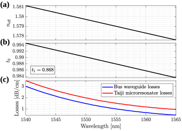
In order to model the experiments, we set the parameters of the device as follow. The perimeter of the taiji racetrack microresonator is fixed imposing , , , while the S-shaped waveguide length is . All these values were derived from the design of the TJMR. The effective mode index was extrapolated by slightly modifying the one reported in [25] to match the taiji experimental resonances (see Fig. 9 (a)). The BW length was measured from the design . and the reflection coefficients () were extrapolated from the experimental FP fringes. The spectral dependence of the transmission coefficients , and of the losses were estimated by measuring the transmittance, the reflectance and the propagation losses (see Fig. 9). . By fitting the experimental spectra in the linear and nonlinear regimes, we observed lower propagation losses in the BW than in the TJMR. This difference is due to the bending loss in the microresonator.
.2 Appendix: taiji microresonator internal energy calculation
To simulate the device in the nonlinear regime, it is needed to evaluate the internal energy in the following regions: microresonator, S-shaped waveguide and BW. Since the method is the same, we will describe only the calculation of the microresonator internal energy. Following [25], the TJMR can be analyzed through twelve different electric fields. Precisely, half of them fields propagates in the CW direction and the other half in the CCW one. All of these fields can be computed by solving the system of equations shown in [25], for the linear regime or by iterating until convergence for the nonlinear one. To determine the internal energy it is first necessary to calculate the CW and CCW fields at each point of the microresonator. We start from the CW direction and use the fact that from one coupling region to the next and along the wave propagation direction the electric field can be described as , where is the starting position, is the coordinate along the waveguide, and is a complex parameter that accounts for both phase variation and propagation losses (). By transfer matrix multiplication, we compute all the CW () and CCW () fields. Then, the internal energy is the integral of along the microresonator.
.3 Appendix: simulation model
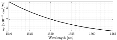
In the linear regime, we used the model presented in [25] to simulate the device. In the nonlinear regime, we extended the equations taking into account that the refractive index is not only wavelength dependent but varies also as a function of the intensity of the electromagnetic wave. As seen in [8], , where is the refractive index in the linear regime, is the coefficient of the thermo-optic nonlinearity, is the Kerr nonlinear index and is the total electromagnetic intensity for the three different regions: microresonator, S-shaped waveguide and BW. To obtain transmissions, reflections, and internal energies as a function of wavelength we process the spectra of all electric fields within the system starting at shorter wavelengths and for each wavelength we evolve the system of field equations to their convergence.
In this model we consider the following relationship between and the propagation losses: , where and are the propagation losses and the microresonator perimeter, respectively. By comparing experimental and simulated spectra, we obtained an estimation of reported in Fig. 10.
Acknowledgement
We acknowledge financial support from the Provincia Autonoma di Trento and the Q@TN initiative. S.B. acknowledges funding from the MIUR under the project PRIN PELM (20177 PSCKT). We thank F. Ramiro Manzano, A. Calabrese and H. M. Price for continuous and insightful exchanges and E. Moser for technical support.
References
- [1] Li Fan, Jian Wang, Leo T. Varghese, Hao Shen, Ben Niu, Yi Xuan, Andrew M. Weiner, and Minghao Qi. An all-silicon passive optical diode. Science, 335(6067):447–450, 2012.
- [2] Ang Li and Wim Bogaerts. Reconfigurable nonlinear nonreciprocal transmission in a silicon photonic integrated circuit. Optica, 7(1):7–14, Jan 2020.
- [3] Parinaz Aleahmad, Mercedeh Khajavikhan, Demetrios Christodoulides, and Patrick LiKamWa. Integrated multi-port circulators for unidirectional optical information transport. Scientific Reports, 7(1):2129, May 2017.
- [4] Bo Peng, Şahin Kaya Özdemir, Fuchuan Lei, Faraz Monifi, Mariagiovanna Gianfreda, Gui Lu Long, Shanhui Fan, Franco Nori, Carl M. Bender, and Lan Yang. Parity–time-symmetric whispering-gallery microcavities. Nature Physics, 10(5):394–398, May 2014.
- [5] Long Chang, Xiaoshun Jiang, Shiyue Hua, Chao Yang, Jianming Wen, Liang Jiang, Guanyu Li, Guanzhong Wang, and Min Xiao. Parity–time symmetry and variable optical isolation in active–passive-coupled microresonators. Nature Photonics, 8(7):524–529, Jul 2014.
- [6] Leonardo Del Bino, Jonathan M. Silver, Sarah L. Stebbings, and Pascal Del’Haye. Symmetry breaking of counter-propagating light in a nonlinear resonator. Scientific Reports, 7(1):43142, Feb 2017.
- [7] Leonardo Del Bino, Jonathan M. Silver, Michael T. M. Woodley, Sarah L. Stebbings, Xin Zhao, and Pascal Del’Haye. Microresonator isolators and circulators based on the intrinsic nonreciprocity of the kerr effect. Optica, 5(3):279–282, Mar 2018.
- [8] A. Muñoz de las Heras, R. Franchi, S. Biasi, M. Ghulinyan, L. Pavesi, and I. Carusotto. Nonlinearity-induced reciprocity breaking in a single nonmagnetic taiji resonator. Physical Review Applied, 15(5):054044, May 2021.
- [9] Horst Dötsch, Norbert Bahlmann, Oleksandr Zhuromskyy, Manfred Hammer, Ludger Wilkens, Reinald Gerhardt, Peter Hertel, and Anatoly F. Popkov. Applications of magneto-optical waveguides in integrated optics: review. J. Opt. Soc. Am. B, 22(1):240–253, Jan 2005.
- [10] Zheng Wang and Shanhui Fan. Optical circulators in two-dimensional magneto-optical photonic crystals. Opt. Lett., 30(15):1989–1991, Aug 2005.
- [11] Zheng Wang, Yidong Chong, J. D. Joannopoulos, and Marin Soljačić. Observation of unidirectional backscattering-immune topological electromagnetic states. Nature, 461(7265):772–775, Oct 2009.
- [12] Lei Bi, Juejun Hu, Peng Jiang, Dong Hun Kim, Gerald F. Dionne, Lionel C. Kimerling, and C. A. Ross. On-chip optical isolation in monolithically integrated non-reciprocal optical resonators. Nature Photonics, 5(12):758–762, Dec 2011.
- [13] Yuya Shoji, Masatoshi Ito, Yuya Shirato, and Tetsuya Mizumoto. Mzi optical isolator with si-wire waveguides by surface-activated direct bonding. Opt. Express, 20(16):18440–18448, Jul 2012.
- [14] Tomoki Ozawa, Hannah M. Price, Alberto Amo, Nathan Goldman, Mohammad Hafezi, Ling Lu, Mikael C. Rechtsman, David Schuster, Jonathan Simon, Oded Zilberberg, and Iacopo Carusotto. Topological photonics. Rev. Mod. Phys., 91:015006, Mar 2019.
- [15] Wei Yan, Yucong Yang, Shuyuan Liu, Yan Zhang, Shuang Xia, Tongtong Kang, Weihao Yang, Jun Qin, Longjiang Deng, and Lei Bi. Waveguide-integrated high-performance magneto-optical isolators and circulators on silicon nitride platforms. Optica, 7(11):1555–1562, Nov 2020.
- [16] J. P. Hohimer, G. A. Vawter, and D. C. Craft. Unidirectional operation in a semiconductor ring diode laser. Applied Physics Letters, 62(11):1185–1187, 1993.
- [17] Svyatoslav Kharitonov and Camille-Sophie Brès. Isolator-free unidirectional thulium-doped fiber laser. Light: Science & Applications, 4(10):e340–e340, Oct 2015.
- [18] Jinhan Ren, Yuzhou G. N. Liu, Midya Parto, William E. Hayenga, Mohammad P. Hokmabadi, Demetrios N. Christodoulides, and Mercedeh Khajavikhan. Unidirectional light emission in pt-symmetric microring lasers. Opt. Express, 26(21):27153–27160, Oct 2018.
- [19] Miguel A. Bandres, Steffen Wittek, Gal Harari, Midya Parto, Jinhan Ren, Mordechai Segev, Demetrios N. Christodoulides, and Mercedeh Khajavikhan. Topological insulator laser: Experiments. Science, 359(6381), 2018.
- [20] Daria Smirnova, Daniel Leykam, Yidong Chong, and Yuri Kivshar. Nonlinear topological photonics. Applied Physics Reviews, 7(2):021306, 2020.
- [21] R J Potton. Reciprocity in optics. Reports on Progress in Physics, 67(5):717–754, apr 2004.
- [22] W. C. Chew. A new look at reciprocity and energy conservation theorems in electromagnetics. IEEE Transactions on Antennas and Propagation, 56(4):970–975, 2008.
- [23] Jan Wiersig. Review of exceptional point-based sensors. Photon. Res., 8(9):1457–1467, Sep 2020.
- [24] Ramy El-Ganainy, Mercedeh Khajavikhan, Demetrios N. Christodoulides, and Sahin K. Ozdemir. The dawn of non-hermitian optics. Communications Physics, 2(1):37, Mar 2019.
- [25] A. Calabrese, F. Ramiro-Manzano, H. M. Price, S. Biasi, M. Bernard, M. Ghulinyan, I. Carusotto, and L. Pavesi. Unidirectional reflection from an integrated “taiji” microresonator. Photonics Research, 8(8):1333–1341, Aug 2020.
- [26] Lukas J. Maczewsky, Matthias Heinrich, Mark Kremer, Sergey K. Ivanov, Max Ehrhardt, Franklin Martinez, Yaroslav V. Kartashov, Vladimir V. Konotop, Lluis Torner, Dieter Bauer, and Alexander Szameit. Nonlinearity-induced photonic topological insulator. Science, 370(6517):701–704, 2020.
- [27] Marcel W. Pruessner, Todd H. Stievater, and William S. Rabinovich. Integrated waveguide fabry-perot microcavities with silicon/air bragg mirrors. Optics Letters, 32(5):533–535, Mar 2007.
- [28] C. A. Barrios, V. R. Almeida, R. R. Panepucci, B. S. Schmidt, and M. Lipson. Compact silicon tunable fabry-perot resonator with low power consumption. IEEE Photonics Technology Letters, 16(2):506–508, Feb 2004.
- [29] C. Castellan, S. Tondini, M. Mancinelli, C. Kopp, and L. Pavesi. Reflectance reduction in a whiskered soi star coupler. IEEE Photonics Technology Letters, 28(17):1870–1873, 2016.
- [30] S. Biasi, F. Ramiro-Manzano, F. Turri, P. Larré, M. Ghulinyan, I. Carusotto, and L. Pavesi. Hermitian and non-hermitian mode coupling in a microdisk resonator due to stochastic surface roughness scattering. IEEE Photonics Journal, 11(2):1–14, 2019.
- [31] Ang Li, Thomas Van Vaerenbergh, Peter De Heyn, Peter Bienstman, and Wim Bogaerts. Backscattering in silicon microring resonators: a quantitative analysis. Laser & Photonics Reviews, 10(3):420–431, May 2016.
- [32] V. Ilchenko and M. L. Gorodetskii. Thermal nonlinear effects in optical whispering gallery microresonators. Laser Physics, 2:1004–1009, 1992.
- [33] Tal Carmon, Lan Yang, and Kerry J. Vahala. Dynamical thermal behavior and thermal self-stability of microcavities. Optics Express, 12(20):4742–4750, Oct 2004.
- [34] C. Schmidt, A. Chipouline, T. Pertsch, A. Tünnermann, O. Egorov, F. Lederer, and L. Deych. Nonlinear thermal effects in optical microspheres at different wavelength sweeping speeds. Optics Express, 16(9):6285–6301, Apr 2008.
- [35] F. Ramiro-Manzano, N. Prtljaga, L. Pavesi, G. Pucker, and M. Ghulinyan. Thermo-optical bistability with si nanocrystals in a whispering gallery mode resonator. Opt. Lett., 38(18):3562–3565, Sep 2013.
- [36] R. W. Boyd. Nonlinear Optics. Academic Press, 2008.
- [37] P. N. Butcher and D. Cotter. The elements of nonlinear optics. Cambridge Studies in Modern Optics. Cambridge University Press, 2008.
- [38] Hyatt M. Gibbs. Optical Bistability: Controlling Light with Light. Academic Press, 1985.
- [39] Vilson R. Almeida and Michal Lipson. Optical bistability on a silicon chip. Opt. Lett., 29(20):2387–2389, Oct 2004.
- [40] A. Trenti, M. Borghi, S. Biasi, M. Ghulinyan, F. Ramiro-Manzano, G. Pucker, and L. Pavesi. Thermo-optic coefficient and nonlinear refractive index of silicon oxynitride waveguides. AIP Advances, 8(2):025311, 2018.
- [41] George N. Ghalanos, Jonathan M. Silver, Leonardo Del Bino, Niall Moroney, Shuangyou Zhang, Michael T. M. Woodley, Andreas Ø. Svela, and Pascal Del’Haye. Kerr-nonlinearity-induced mode-splitting in optical microresonators. Phys. Rev. Lett., 124:223901, Jun 2020.