Multi-pixel Photon Counter for operating the tabletop cosmic-ray detector under loosely controlled conditions
Abstract
Multi-Pixel Photon Counter (MPPC) has been recently emerged and realized as a great type of Silicon Photomultiplier to replace or compensate for the conventional vacuum-based Photomultiplier tubes. MPPC provides many striking features such as high electrical gain, outstanding photon detection efficiency, fast timing response, immunity to the magnetic field, low-voltage operation, compactness, portability, and cost-effectiveness. The report introduces and examines the electrical and optical characteristics of the MPPC under loosely controlled environmental conditions. Also, we report a measurement of the light yield captured by the MPPC when the cosmic ray passes through the plastic scintillator, demonstrating that such setup is suitable to build a simple, cost-effective tabletop cosmic-ray detector for educational and research purposes.
I Introduction
I.1 Silicon photodiode, avalanche breakdown, and Geiger mode
A photodiode, as illustrated in the left of Fig. 1, is made from a silicon doped p-n junction which establishes a depletion region of mobile carriers in the thermal equilibrium Neamen (2011). When a photon is incident on silicon, a pair of electrons and holes are created via the photoelectric effect in the depletion region. When a reverse-biased voltage is applied to the silicon photodiode, generating a high electric field across the depletion region, the produced charge carriers experience an increase in the kinetic energy and collide with the lattice atoms, eventually losing their energy as thermal phonons. When the applied voltage is high enough, the carriers have sufficient power to ionize the lattice atoms, inducing additional electron-hole pairs and resulting in a chain of ionization called avalanche breakdown or avalanche multiplication. Thus, an absorbed photon can trigger a macroscopic electrical current, allowing us to distinctly detect the photon’s incident. A photodiode called Avalanche PhotoDiode (APD) is designed to operate in such conditions. The charge collected from the avalanche multiplication is expressed in terms of the electron charge unit and called electrical gain.
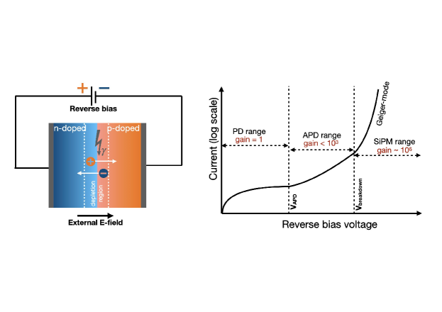
When the operating voltage is lower than the APD breakdown voltage, a turning point where the silicon suddenly becomes conductive subjecting to the external electric field, the electrical gain has a linear response to the applied voltage and typically less than one thousand. When the reverse bias voltage exceeds the APD breakdown voltage, the electrical gain increases drastically. The APD becomes a binary response, such that the output charge is independent of the intensity of incident photons. Silicon Photomultiplier (SiPM), denoted for the APD operated in this so-called Geiger mode, has an electrical gain of . Classification of the photodiode, APD, and SiPM basing on the amplitude of the reverse bias voltage is illustrated on the right of Fig. 1.
I.2 Multi-Pixel Photon Counter
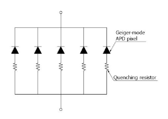
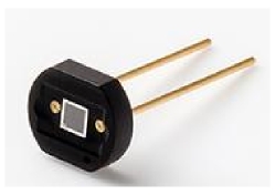
Multi-Pixel Photon Counter (MPPC) Ghassemi et al. (2018) is one of the most used SiPM, developed by Hamamatsu, Japan. It is fabricated on a monolithic silicon crystal, with a composite-metal quenching resistor around each APD, forming a so-called pixel. The multiple pixels are arranged in two dimensions, connected in parallel with a common reverse bias voltage, and read by a united output. An equivalent circuit of MPPC and a close-up view of a single MPPC are shown in Fig. 2. Since each pixel produces the same electrical current per incident photon, the MPPC signal summing the currents from the fired pixels is practically equivalent to the number of incident photons, providing MPPC excellent capability to count photons.
The first generation of Hamamatsu MPPCs, the S10362 series, was announced in 2007 Ohashi (2019). Six years later, the second generation of MPPCs, the S1257x series, was released with lower afterpulse and improved photon detection efficiency (PDE) but still relatively high crosstalk. In 2015, they introduced a new generation of MPPCs, the S1336x series, with lower crosstalk and afterpulse and higher fill factor. Compared to the S1257x series, this series provides a higher PDE for a broader range of wavelengths from UV to visible light. In 2017, a new lineup of products, the S14160/S14161 series, dedicating to the time-of-flight application such as the Positron Emission Tomography (PET) with excellent coincidence time resolution. Recently, two additional lineups of products Yamamoto et al. (2019) have been introduced: (i) S14520 series designed for the Cherenkov telescopes with high PDE in the UV region, and (ii) S14160 series with a pixel size of 10 and 15 and new design of the pixel trench, achieving lower noise and crosstalk, higher PDE, wide dynamic range, and lower power consumption.
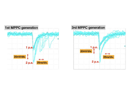
Fig. 3 shows the electrical pulses induced by the thermal noise with two generations of the MPPC. The signal is amplified with a NIM amplifier module by a factor of one hundred and read out by the Tektronix TBS1104 100Mhz bandwidth digital storage oscilloscope. The electrical pulses with a single photoelectron (p.e) and two p.e. are visibly well distinguished for both MPPC generations. The signal’s rising time is around a few ns and the signal’s decay time is a few of 10 ns.
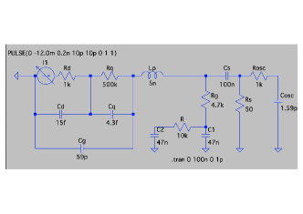
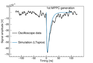
As studied in Ref. Seifert et al. (2009), the MPPC signal can be well-simulated with an equivalent electronic circuit implemented in the SPICE simulation program111http://bwrcs.eecs.berkeley.edu/Classes/IcBook/SPICE/. We have worked out to come up with a SPICE model presented on the left of Fig. 4 for the MPPC S10362-13-050C. An MPPC pixel is modeled by a capacitor Cd = 15 fF and a resistor Rd = 1 k. The quenching is simulated by a capacitor of Cq = 4.3 fF and Rq = 500 k. The parasitic capacitance is Cg = 59 pF. The right of Fig. 4 shows the agreement between the MPPC signal recorded by oscilloscope TBS1104 and SPICE simulation of the MPPC electrical model. The effect of the 100 Mhz bandwidth of the oscilloscope is included in the simulation with Rosc = 1 k and Cosc = 1.59 pF.
With a large number of excellent features and a wide selection of product lines, MPPC is applicable in diverse fields, including, but not limited to, extremely low-light detection in particle and nuclear physics, time-of-flight-based distance measurement for the automotive vehicle, fluorescence and chemiluminescence spectroscopy, biochemical sensors, single molecular detection, positron emission tomography in the medical imaging system, quantum computing and crytography 222see https://www.hamamatsu.com/jp/en/product/optical-sensors/mppc/application/index.html. In particle physics, mass production of MPPCs was firstly used in the T2K experiment Yokoyama et al. (2010) in 2008 with approximately 60,000 MPPC pieces.
II Characteristics of MPPC under temperature-uncontrolled conditions
In this section, we explore the electrical and optical characteristics of MPPC. Notably, we examine these characteristics with measurements where the environmental conditions such as temperature and humidity are not strictly controlled. We use a commercial air conditioner to regulate the temperature through our measurements. The room temperature is checked occasionally with an indoor thermometer and valued at C. However, the MPPC temperature is not measured precisely and is not monitored continuously.
II.1 Electrical gain
Electrical gain of MPPC is defined as the number of charge carriers (electrons or holes) produced from an incident photon on a single pixel of MPPC as follows
| (1) |
where is the output charge of avalanche multiplication; C is the elementary charge; is the overall pixel capacitance; and and are the operating voltage and the breakdown voltage of the MPPC respectively. The over-voltage, defined as , is among the most imporant operational parameters of MPPC. The MPPC’s electrical gain is expected to be linear with since the higher the over-voltage is, the more available ionization energy for the charge carriers is. From Eq. 1, with a pixel capacitor of , for example, and an over-voltage of , MPPC can attain an electrical gain of , which is at similar level as the PMT.
At higher temperatures, the breakdown voltage increases since the lattice vibrations become stronger. Avalanche carriers are more likely to lose kinetic energy via scattering with the lattice atoms, reducing ionization probability. As a result, the gain declines with the increase of temperature. Hence, to maintain a stable operation, it is often to either keep the MPPC in a temperature-controlled environment or employ a temperature compensation circuit to adjust the reverse bias voltage automatically. However, in this study, we will examine the linearity of the MPPC electrical gain when the environmental condition for MPPC operation is not strictly controlled.
Measuring the electrical gain of the MPPC
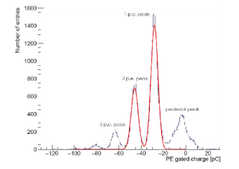
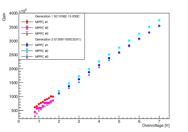
To measure the electrical gain of the MPPC, a nm-wavelength LED333The wavelength is selected since it is close to the photon detection efficiency peak of the MPPC is used as the light source. A reverse-biased voltage is supplied to the MPPC via a low-noise regulated DC power supply. The raw MPPC signal then is amplified by a NIM RPN-092 PM amplifier 444Access online at https://www.h-repic.co.jp/pdf/NIM_RPN_090-091.pdf. The amplified signal is digitized by the DRS4 Evaluation Board 555Access online at https://www.psi.ch/sites/default/files/2020-02/manual_rev51.pdf and sent through a USB connection to a DAQ computer. The MPPC digitized pulses are integrated over a predefined timing window, producing a charge histogram, for example, as shown in the left of Fig.5. The histogram has peaks corresponding to the pedestal (readout noise), one p.e., two p.e., etc. pulses of the MPPC. The output charge equivalent to one incident photon is computed from the peak-to-peak interval between any consecutive peaks, which are determined by fitting a multi-Gaussian function to the charge histogram. We measure the electrical gain with two different types of MPPC and at different values of the over-voltage. The right of Fig.5 shows that the electrical gains of the two MPPC generations are varied linearly with the applied over-voltage. Notably, excellent linearity is achieved even where the environmental conditions are not controlled strictly. Also, we can have an electrical gain of if operating MPPC with 3 V over-voltage. The results are corrected for the electronic gain added from the NIM amplifier and the DRS4.
II.2 Thermal and optical noises
There are three noise components induced during the MPPC operation: dark noise, crosstalk, and afterpulses.
Dark noise
The so-called dark noise is induced randomly by the thermal excitation in the crystal lattice of the MPPC, producing signals indistinguishable from those due to the photoelectric effect. The dark noise rate is proportional to the photosensitive area of the MPPC, the over-voltage, and the temperature. Reducing the noise is of central importance in the MPPC development since, compared to the vacuum-based photomultiplier, MPPC is relatively noisier. For the first generation of MPPC, as showed in the following measurement, the high rate of dark noise of 1 MHz is observed. The noise is suppressed significantly, a factor of 10, from the third generation of MPPC. In the practice of the experiment, the dark noise can be mitigated by applying a trigger threshold that is significantly higher than the noise level. For the extremely low-light measurement, like dark matter search, the MPPC dark noise can be technically suppressed by having MPPC operated in the cryogenic condition.
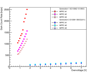
Measuring the dark noise rate of the MPPC
To minimize the effect of the ambient light, the MPPC is placed inside an aluminum box and further covered with layers of black sheets. The dark noise rate, also known as the dark count rate, is defined as the rate of discriminated pulse above a preset voltage threshold corresponding to 0.5 p.e. pulse. The voltage threshold is determined according to the over-voltage. In this measurement, the dark count rates of two generations of MPPC, the first generation SC10362-13-050C and the third generation S13081-050CS, are measured. The result is shown in the left plot of Fig. 6. We observe a difference in the dark count rates between the two MPPC generations. The dark count rate of the third MPPC generation is significantly lower than the first one at the same over-voltage. Also, the dark count rates of MPPCs in the first generation increase dramatically while the rates in the third generation rise gradually as a function of the over-voltage, showing a better performance of the latter. The result concludes the excellent linearity of the dark noise rate on the over-voltage. For practical use of MPPC, the trade-off between the high electrical gain and the low dark noise rate must be considered.
Afterpulses and optical crosstalk
In a given pixel, along with the genuine pulse trigged by the primary avalanche, the charge carriers, trapped in the same pixel or induced to a neighboring pixel, can avalanche the second pulse called afterpulse or optical crosstalk, respectively. Both types of noise are characterized by the relative timing to the genuine pulse. If the afterpulses are released during the pixel’s recovery, their amplitudes are smaller than the one p.e. pulse. On the other hand, if afterpulse is avalanched after the pixel’s recovery, their amplitudes and shapes are indistinguishable from a genuine pulse. Afterpulses can be observed on the trail of the left waveform shown in Fig. 3. Prompt crosstalk, which happens simultaneously with the primary pulse, heightens the output charge since the pixels are connected in parallel. The two p.e. pulse observed in Fig. 3 is likely due to the crosstalk. In another scenario, the crosstalk pulse can be delayed and almost indistinguishable from the delayed afterpulse.
Measuring the prompt crosstalk of the MPPC
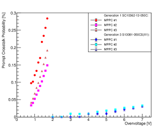
The prompt crosstalk probability is estimated and measured utilizing the same setup as dark count rate measurement. Since we expect a prompt crosstalk pulse superimposes more than one photon, the crosstalk probability is formulated as the ratio of dark count rate at 0.5 p.e. and 1.5 p.e. thresholds levels
| (2) |
The result illustrated in the right plot of Fig.6 shows that the crosstalk probability of the two MPPC generations has the same behavior as the dark count rate. The crosstalk probabilities are about 10-30 in the first MPPC generation and less than in the first 3rd one.
Although the environmental conditions are not strictly controlled, our above measurements of the electric gain, dark noise rate, and the prompt crosstalk probability are in good agreement with the measurements in Ref. Fuminao Hosomi (2016), affirming that MPPC can function well in such conditions.
III A tabletop cosmic-ray detector with scintillator and MPPC
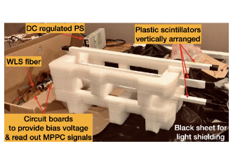
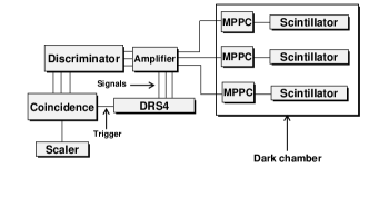
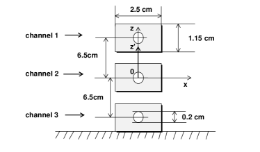
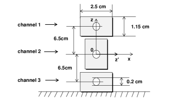
To demonstrate the MPPPC’s application in particle and nuclear physics, we construct a simple tabletop cosmic-ray detector with the plastic scintillator, the wavelength shifting fiber (WLS), and the MPPC. The schematic setup of the three-channel detector is shown on the top-left of Fig.7. Each channel is formed by one extruded 61 cm 2.5 cm 1.15 cm plastic scintillator666Considering an integrated cosmic-ray flux of , events per second is estimated with this setup. A smaller-sized plastic scintillator can be used but need more time to collect data for having the same statistics with a 2 mm-diameter hole in the middle to house the Y-11(200)-typed 1.2-diameter WLS fiber, which is coupled to one MPPC third-generation S13081-050CS(X1). When charged particles, like muons, travel through the scintillator, they deposit energy and produce a flash of scintillation light. The WLS fiber collects these lights and guides them to the MPPC before detected. A coincident signal of the top and bottom channels is used as a trigger system to recognize whenever vertical cosmic rays are coming and acquire the middle one to record the signal. A typical waveform of the cosmic-ray-like signal is shown in the top-right of Fig.7. We investigate the MPPC response and decay time of the scintillation light by fitting the waveform to an exponential-modified Gaussian function.
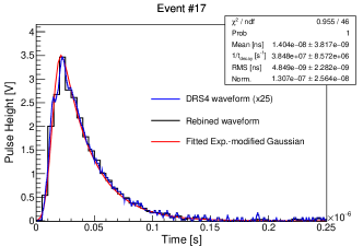
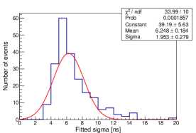
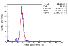
The fitted Gaussian width characterizes the MPPC response to the cosmic-ray deposition and the fitted decay time presents how fast the scintillation light is produced. The result is shown in the plots of Fig.8. The Gaussian width is estimated at ns and the mean value of the fitted decay times is ns.
The integrated charge of the signal waveform is used to estimate the number of photoelectrons corresponding to the energy deposit of cosmic ray muons, which is about 2 MeV/cm on average Groom et al. (2001). The bottom plots of Fig. 9 show the distributions of the photoelectron number captured by the MPPC for two different widths of scintillator of 1.15 cm and 2.5 cm. We find that a Landau function does not provide a good fit to the distribution, but the convoluted Landau and Gaussian function, affirming the fluctuation of the energy loss by charged particle’s ionization in a thin layer of material.
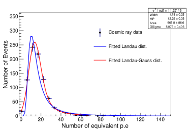
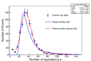
In Fig.9, the numbers of detected photoelectrons are and corresponding to the 1.15 cm-thick and 2.5 cm-thick scintillators, respectively. The result affirms that the energy deposit of the charged particle is proportional to the thickness of the scintillation material. Also, it shows that the number of photoelectrons detected when a cosmic ray passes through is well above the noise level. Thus, we conclude that MPPC with the plastic scintillation is suitable for tracking the charged particle in a lab room with loosely controlled conditions.
IV SUMMARY
In this paper, we have introduced and measured the characteristics of the MPPC under loosely controlled conditions. We conclude that the MPPC performance is still stable and reliable enough for practical use even in such situations. We also measured the scintillation light yield collected by the MPPC when the cosmic rays pass through and deposit energy on the plastic scintillator. We observe more than ten photoelectrons per 2 MeV energy deposition, well above the background level. The result concludes that MPPC could be used along with the cm or thicker plastic scintillator to construct the simple, cost-effective tabletop cosmic-ray detector for educational and research purposes.
References
- Neamen (2011) D. A. Neamen, Semiconductor physics and devices: basic principles (McGraw-Hill, 2011).
- Ghassemi et al. (2018) A. Ghassemi et al., A technical guide to silicon photomultipliers (MPPC) - Overview, Tech. Rep. (Hamamatsu Photonics K.K., 2018).
- (3) Hamamatsu Photonics K.K., “Multi-Pixel Photon Counters (MPPCs/SiPMs),” https://www.hamamatsu.com/jp/en/product/optical-sensors/mppc/index.html, [Online; accessed: June 2020].
- Ohashi (2019) Y. Ohashi, “Current status of hamamatsu si detectors for collider experiments,” https://indico.cern.ch/event/818783/contributions/3598485/ (2019).
- Yamamoto et al. (2019) K. Yamamoto, T. Nagano, R. Yamada, T. Ito, and Y. Ohashi, JPS Conf. Proc. 27, 011001 (2019).
- Seifert et al. (2009) S. Seifert, H. T. Van Dam, J. Huizenga, R. Vinke, P. Dendooven, H. Lohner, and D. R. Schaart, IEEE Transactions on Nuclear Science 56, 3726 (2009).
- Yokoyama et al. (2010) M. Yokoyama et al., Nucl. Instrum. Meth. A 622, 567 (2010), arXiv:1007.2712 [physics.ins-det] .
- Fuminao Hosomi (2016) Fuminao Hosomi, “Characterization of multi-pixel photon counters for a new neutrino detector,” http://hep.phys.s.u-tokyo.ac.jp/wordpress/wp-content/uploads/2016/06/mth2016_hosomi.pdf (2016), [Online; accessed: May 2021].
- Groom et al. (2001) D. E. Groom, N. V. Mokhov, and S. I. Striganov, Atom. Data Nucl. Data Tabl. 78, 183 (2001).