Remote state preparation of single photon orbital angular momentum lattices
Abstract
Optical beams with periodic lattice structures have broadened the study of structured waves. In the present work, we generate spin-orbit entangled photon states with a lattice structure and use them in a remote state preparation protocol. We sequentially measure spatially-dependent correlation rates with an electron-multiplying intensified CCD camera and verify the successful remote preparation of spin-orbit states by performing pixel-wise quantum state tomography. Control of these novel structured waves in the quantum regime provides a method for quantum sensing and manipulation of periodic structures.
I Introduction
Advances in experimental methods have enabled the creation of structured beams of neutrons Sarenac et al. (2019). Matter-waves with structured phase fronts are formed with many different strategies ranging from spatially-dependent magnetic fields Karimi et al. (2012); Sarenac et al. (2018a); Rubinsztein-Dunlop et al. (2016) to spiral phase plates made of thin graphite films Uchida and Tonomura (2010). The formalism of quantum information science is system agnostic, allowing translation of the physics of one system to that of another. In order to move from neutrons to photons, spin is replaced with polarization, and the magnetic field gradients are replaced with birefringent gradients. Using this correspondence, a lattice of spin-orbit states originally developed for neutrons has been implemented with photons. Optical lattices have led to studies of optical Talbot physics of structured orbital angular momentum (OAM) light beams Ikonnikov et al. (2020); Schwarz et al. (2020), optical lattice structure shaping Li et al. (2018); Han et al. (2019), and direct detection of optical spin-orbit states by the human eye Sarenac et al. (2020a, b). By translating the physics of a periodic structure of spin-orbit states further in photonics, we can take advantage of additional capabilities such as multi-particle entanglement. This opens the possibility for quantum correlations in structured beams and the capabilities that come with them.
The periodicity of these structured waves are suited for quantum sensing or control of periodic structures Andersen et al. (2006); He et al. (1995); Schmiegelow and Schmidt-Kaler (2012). The interference of OAM lattices has been used to build all-optical quantum memory devices Luo et al. (2017), and the average deviation of atoms relative to their lattice sites has been measured continuously and nondestructively with optical lattices Morrow et al. (2002). OAM provides access to a high-dimensional Hilbert space which can enhance the information capacity of a single particle Forbes and Nape (2019); Barreiro et al. (2008), while the more easily manipulated polarization degree of freedom can be used for enhanced control and measurement Marrucci et al. (2011); Milione et al. (2015); Vallone et al. (2014); Schmiegelow et al. (2016); Erhard et al. (2018); Fickler et al. (2016); Sit et al. (2017). Working with the OAM and polarization degrees of freedom simultaneously combines the advantageous characteristics of both Nagali et al. (2009); Wang et al. (2011); Diamanti et al. (2016); Mafu et al. (2013); Heo et al. (2017). To characterize and verify spin-orbit entanglement, quantum state tomography has been done previously using OAM projective measurements with a spatial light modulator Erhard et al. (2015), and with spatially-dependent polarization measurements using an intensified CCD camera Fickler et al. (2014). Structured waves have recently attracted attention in the quantum communication community specifically in turbulence studies Nape et al. (2021); Zhou et al. (2021). Correlations between polarization and OAM have shown preservation of the encoded state after propagation through scattering media Gianani et al. (2020).
In this work, we generate spin-orbit entanglement between the polarization of one photon and the transverse beam profile of the other. Polarization measurement enables production of distinctly different structured beams, and the correlations between these beams and the polarization can be used to verify entanglement. We confirm the entanglement using a quantum state tomography procedure between the polarization of one photon, and the position-dependent polarization of its entangled partner. With these correlations, we implement a remote state preparation (RSP) protocol to prepare structured single photon beams. RSP involves transferring a quantum state known by one party to another party via entanglement Pati (2000); Bennett et al. (2001); Lo (2000), and has applications in large-scale quantum communication networks Leung and Shor (2003); Dakić et al. (2012); Barreiro et al. (2010); Peters et al. (2005). In our case, a RSP protocol is used to prepare signal photon spatial patterns conditioned on idler photon polarization measurements. The spin-orbit coupling method presented expands lattice structured light preparation and measurement further into the quantum regime.
II Theory
We consider polarization-entangled photon pairs which are described by the Bell state , where we denote right-handed circular and left-handed circular polarization states by and . Polarization states and correspond to and , respectively, in the computational basis. As described in Ref. Sarenac et al. (2018b) in more detail, a lattice of spin-orbit states is obtained by passing circularly polarized light through perpendicular pairs of birefringent linear gradients whose optical axes are relatively offset by . The operators of the two perpendicular birefringent gradients are described by
| (1) |
where the origin of the gradients is given by , are Pauli matrices and is the spacing between neighboring lattice sites with wavelength , prism birefringence and prism incline angle . By sending one photon through sets of Lattice of Optical Vortices (LOV) prism pairs, we prepare the spin-orbit entangled lattice state
| (2) |
where describes the incoming Gaussian beam envelope, and is the two-dimensional identity matrix.
Applying the operators in Eq. (1) on polarization states and yields
| (3) |
and
| (4) |
where and are complex-valued amplitudes. The LOV prism pairs are thus represented by unitary matrices that couple the polarization of a photon to its spatial mode. Different polarization projections on the spin-orbit lattice state lead to different intensity patterns. To simulate these intensity patterns, polarization projections were applied to Eq. (2). Furthermore, we applied a Gaussian beam profile to the theoretical images in order to account for the beam intensity envelope.
The two-photon density matrix is recovered via maximum likelihood quantum state tomography. The information of interest is encoded in the complex two-dimensional spatial functions as seen in Eq. (3) and Eq. (4), and a single photon camera captures intensity measurements of the entire pattern simultaneously. Each of the camera’s pixels are treated like individual detectors when computing tomography. A pixel-wise algorithm loops through them and uses the maximum likelihood tomography approach specified in Ref. James et al. (2001). By recovering the density matrix at every pixel, we can witness entanglement between polarization and each transverse position in the beam and verify remote state preparation.
III Experimental Method
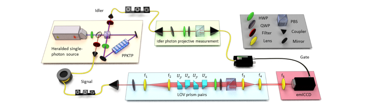
A schematic of our experimental setup is depicted in Fig. 1. We generate entangled photon pairs using type-II spontaneous parametric down-conversion in a Sagnac interferometer Schwarz et al. (2020). We pump a mm long periodically-poled potassium titanyl phosphate crystal (ppKTP) with a nm continuous wave diode laser to produce signal and idler photon pairs, both centered at nm with a spectral bandwidth (FWHM) of approximately nm. The outputs of the interferometer are coupled into single-mode fibers. Immediately following the polarization-entangled source, we measured a polarization state fidelity of . The signal photons are first sent through an optical telescope to be magnified by a factor of , followed by two sets of LOV prism pairs. The magnification controls the number of lattice periods in the emerging intensity pattern by illuminating a larger portion of the prisms.
The modified signal photons are sent through polarization analyzing optics which consist of a half-wave plate (HWP), a quarter-wave plate (QWP) and a polarizing beam splitter (PBS). Finally, we demagnify the beam by a factor of by means of a second optical telescope and send the signal photons to an emICCD camera (PI-Max4: 1024 EMB). The idler photons are directly sent to polarization analyzing optics and detected by an avalanche photodiode which triggers the emICCD. Signal photons pass through a m spool of single-mode fiber in order to compensate for electronic delay. Once the idler photon triggers the camera, an electronic gate in the emICCD collects data for ns. We measure all 16 combinations of the tomographically complete set , , , and on the signal and idler photons. For each polarization measurement, we accumulate signal photons for exposures and trigger the camera at a rate of kHz. Every exposure takes about sec to record. We focus on a pixel area on the camera, where each pixel is m m.
IV Experimental Results
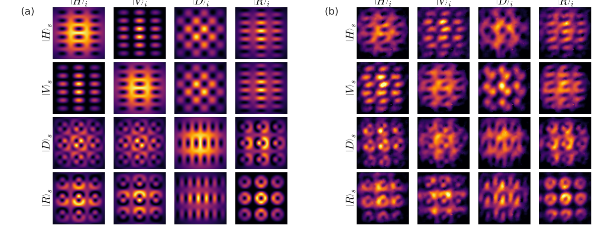
In Fig. 2, we show a comparison of theoretically calculated and experimentally measured two-dimensional intensity patterns for all 16 measurement configurations. The theoretical predictions in Fig. 2(a) and the experimental data in Fig. 2(b) are in qualitative agreement. LOV prism pair alignment challenges associated with setting and maintaining the phase leads to slight pattern distortion as compared with theory. In both cases, we used a grid of points. In the image plane of the emICCD, the simulated lattice spacing in Fig. 2(a) is mm, while the measured lattice spacing in Fig. 2(b) is mm. For the purpose of computing the density matrices, the raw counts from the sum of exposures are used. However, when viewing the intensity distributions, the raw intensity profiles are post-processed using background subtraction and an adaptive two-dimensional Gaussian image filter.
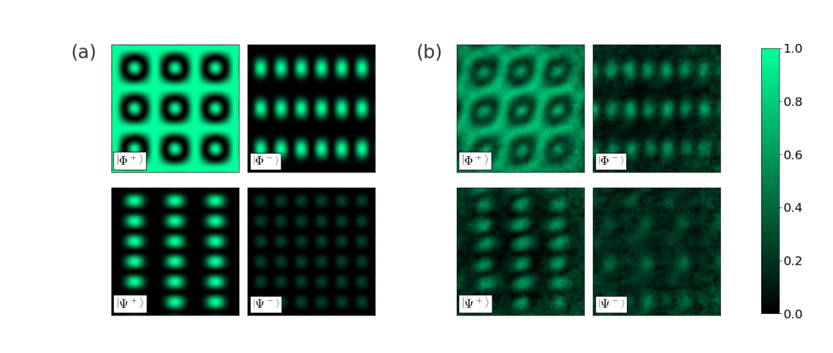
We take the theoretical (Fig. 3(a)) and experimental (Fig. 3(b)) density matrices calculated at each pixel position and present the fidelity with each of the four Bell states. For example, the top left image in Fig. 3(a) shows how similar the theoretical density matrices, , are to the Bell state by plotting the fidelity, , at every pixel position . The input to the LOV prism pairs is the Bell state as shown in Eq. (2), and you can see from the top left images in Fig. 3(a) and Fig. 3(b) that the areas around the ring-shaped regions, along with the centre of these regions, have had a phase rotation of a multiple of from the starting Bell state. Looking at the four quadrants of Fig. 3(a) and Fig. 3(b), it is apparent that at different pixel positions, the input state has been rotated to other Bell states. Pixel-wise quantum state tomography therefore enables a visualization technique to show how the spin-orbit lattice state evolves across the transverse beam profile. The theoretical and experimental Bell state fidelities plotted in Fig. 3 are in qualitative agreement, and there is a reduced experimental fidelity across all pixels.
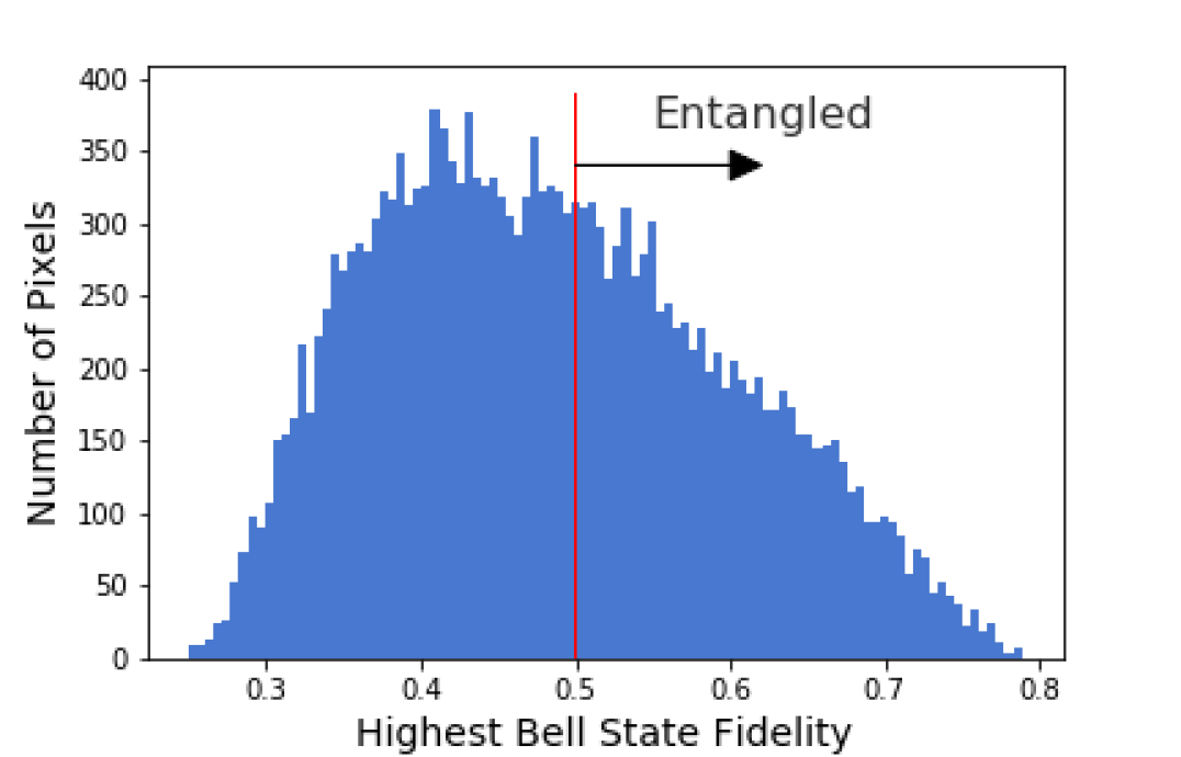
A histogram presenting the highest Bell state fidelity at each pixel position is presented in Fig. 4. In the experimental case, 42.5% of pixel locations have a fidelity of more than 0.5 with one of the four Bell states. This is a witness of entanglement between the signal photons measured at the pixel locations and the idler photons that trigger the camera because qubit separable states cannot achieve a Bell state fidelity of more than 0.5 Horodecki et al. (2009). In the theoretical case, 85.7% of pixel locations are a witness of entanglement in this way, so even with perfect image contrast and quantum state preparation, not all positions of this pattern significantly overlap with one of the four Bell states. However, plotting Bell state fidelities helps to illustrate the spatially-dependent rotation of the two-photon spin-orbit lattice state.
V Conclusion
In this work, we report on the implementation of a remotely prepared optical lattice of spin-orbit states by means of polarization-entangled photon pairs. We experimentally verify the successful remote preparation of this spin-orbit entangled state with an emICCD camera using a pixel-wise maximum likelihood quantum state tomography algorithm. We observe that the entanglement present in the joint two-photon quantum state transforms such that there are overlaps with different Bell states depending on which portion of the LOV prism pairs the signal photon travels through. Furthermore, we have shown that pixel-wise tomography on images acquired by an emICCD camera provides a useful method for observing spatially-dependent two-photon states.
In future work, we plan to study lattices with a higher number of LOV prism pairs to access higher radial quantum numbers and thus a larger alphabet to encode spin-orbit states for quantum communication protocols. Our work advances the study of quantum correlations of structured beams with lattice frameworks, as well as quantum sensing and control of periodic structures where we can take advantage of the novel lattice patterns of our spin-orbit states.
Acknowledgments
The authors would like to thank Katanya Kuntz, Ruoxuan Xu, and Jean-Philippe MacLean for helpful discussions and tips. This research was supported in part by the Canadian Excellence Research Chairs (CERC) program, the Natural Sciences and Engineering Research Council of Canada (NSERC), Canada Research Chairs, Industry Canada and the Canada Foundation for Innovation (CFI), Ontario Research Fund (ORF), and the Canada First Research Excellence Fund (CFREF).
References
- Sarenac et al. (2019) D. Sarenac, C. Kapahi, W. Chen, C. W. Clark, D. G. Cory, M. G. Huber, I. Taminiau, K. Zhernenkov, and D. A. Pushin, Proceedings of the National Academy of Sciences 116, 20328 (2019).
- Karimi et al. (2012) E. Karimi, L. Marrucci, V. Grillo, and E. Santamato, Phys. Rev. Lett. 108, 044801 (2012).
- Sarenac et al. (2018a) D. Sarenac, J. Nsofini, I. Hincks, M. Arif, C. W. Clark, D. G. Cory, M. G. Huber, and D. A. Pushin, New Journal of Physics 20, 103012 (2018a).
- Rubinsztein-Dunlop et al. (2016) H. Rubinsztein-Dunlop, A. Forbes, M. V. Berry, M. R. Dennis, D. L. Andrews, M. Mansuripur, C. Denz, C. Alpmann, P. Banzer, T. Bauer, E. Karimi, L. Marrucci, M. Padgett, M. Ritsch-Marte, N. M. Litchinitser, N. P. Bigelow, C. Rosales-Guzmán, A. Belmonte, J. P. Torres, T. W. Neely, M. Baker, R. Gordon, A. B. Stilgoe, J. Romero, A. G. White, R. Fickler, A. E. Willner, G. Xie, B. McMorran, and A. M. Weiner, Journal of Optics 19, 013001 (2016).
- Uchida and Tonomura (2010) M. Uchida and A. Tonomura, Nature 464, 737 (2010).
- Ikonnikov et al. (2020) D. A. Ikonnikov, S. A. Myslivets, M. N. Volochaev, V. G. Arkhipkin, and A. M. Vyunishev, Scientific Reports 10, 20315 (2020).
- Schwarz et al. (2020) S. Schwarz, C. Kapahi, R. Xu, A. R. Cameron, D. Sarenac, J. P. W. MacLean, K. B. Kuntz, D. G. Cory, T. Jennewein, K. J. Resch, and D. A. Pushin, Phys. Rev. A 101, 043815 (2020).
- Li et al. (2018) X. Li, H. Ma, H. Zhang, Y. Tai, H. Li, M. Tang, J. Wang, J. Tang, and Y. Cai, Opt. Express 26, 22965 (2018).
- Han et al. (2019) Y.-J. Han, Z.-Y. Rong, L. Zhang, and X.-Y. Chen, Appl. Opt. 58, 6325 (2019).
- Sarenac et al. (2020a) D. Sarenac, C. Kapahi, A. E. Silva, D. G. Cory, I. Taminiau, B. Thompson, and D. A. Pushin, Proceedings of the National Academy of Sciences 117, 14682 (2020a).
- Sarenac et al. (2020b) D. Sarenac, A. E. Silva, C. Kapahi, B. Thompson, D. G. Cory, and D. A. Pushin, “Human psychophysical discrimination of spatially dependant pancharatnam-berry phases in optical spin-orbit states,” (2020b), arXiv:2010.09619 [physics.optics] .
- Andersen et al. (2006) M. F. Andersen, C. Ryu, P. Clade, V. Natarajan, A. Vaziri, K. Helmerson, and W. D. Phillips, Phys. Rev. Lett. 97, 170406 (2006).
- He et al. (1995) H. He, M. E. J. Friese, N. R. Heckenberg, and H. Rubinsztein-Dunlop, Phys. Rev. Lett. 75, 826 (1995).
- Schmiegelow and Schmidt-Kaler (2012) C. Schmiegelow and F. Schmidt-Kaler, The European Physical Journal D 66, 157 (2012).
- Luo et al. (2017) X.-W. Luo, X. Zhou, J.-S. Xu, C.-F. Li, G.-C. Guo, C. Zhang, and Z.-W. Zhou, Nature Communications 8, 16097 (2017).
- Morrow et al. (2002) N. V. Morrow, S. K. Dutta, and G. Raithel, Phys. Rev. Lett. 88, 093003 (2002).
- Forbes and Nape (2019) A. Forbes and I. Nape, AVS Quantum Science 1, 011701 (2019).
- Barreiro et al. (2008) J. T. Barreiro, T.-C. Wei, and P. G. Kwiat, Nature Physics 4, 282 (2008).
- Marrucci et al. (2011) L. Marrucci, E. Karimi, S. Slussarenko, B. Piccirillo, E. Santamato, E. Nagali, and F. Sciarrino, Journal of Optics 13, 064001 (2011).
- Milione et al. (2015) G. Milione, M. P. J. Lavery, H. Huang, Y. Ren, G. Xie, T. A. Nguyen, E. Karimi, L. Marrucci, D. A. Nolan, R. R. Alfano, and A. E. Willner, Opt. Lett. 40, 1980 (2015).
- Vallone et al. (2014) G. Vallone, V. D’Ambrosio, A. Sponselli, S. Slussarenko, L. Marrucci, F. Sciarrino, and P. Villoresi, Phys. Rev. Lett. 113, 060503 (2014).
- Schmiegelow et al. (2016) C. T. Schmiegelow, J. Schulz, H. Kaufmann, T. Ruster, U. G. Poschinger, and F. Schmidt-Kaler, Nature Communications 7, 12998 (2016).
- Erhard et al. (2018) M. Erhard, R. Fickler, M. Krenn, and A. Zeilinger, Light: Science &Amp; Applications 7, 17146 (2018).
- Fickler et al. (2016) R. Fickler, G. Campbell, B. Buchler, P. K. Lam, and A. Zeilinger, Proceedings of the National Academy of Sciences 113, 13642 (2016).
- Sit et al. (2017) A. Sit, F. Bouchard, R. Fickler, J. Gagnon-Bischoff, H. Larocque, K. Heshami, D. Elser, C. Peuntinger, K. Günthner, B. Heim, C. Marquardt, G. Leuchs, R. W. Boyd, and E. Karimi, Optica 4, 1006 (2017).
- Nagali et al. (2009) E. Nagali, F. Sciarrino, F. De Martini, L. Marrucci, B. Piccirillo, E. Karimi, and E. Santamato, Phys. Rev. Lett. 103, 013601 (2009).
- Wang et al. (2011) C. Wang, Y. Zhang, and R. Zhang, Opt. Express 19, 25685 (2011).
- Diamanti et al. (2016) E. Diamanti, H.-K. Lo, B. Qi, and Z. Yuan, npj Quantum Information 2, 16025 (2016).
- Mafu et al. (2013) M. Mafu, A. Dudley, S. Goyal, D. Giovannini, M. McLaren, M. J. Padgett, T. Konrad, F. Petruccione, N. Lütkenhaus, and A. Forbes, Phys. Rev. A 88, 032305 (2013).
- Heo et al. (2017) J. Heo, M.-S. Kang, C.-H. Hong, H.-J. Yang, S.-G. Choi, and J.-P. Hong, Scientific Reports 7, 10208 (2017).
- Erhard et al. (2015) M. Erhard, H. Qassim, H. Mand, E. Karimi, and R. W. Boyd, Phys. Rev. A 92, 022321 (2015).
- Fickler et al. (2014) R. Fickler, R. Lapkiewicz, S. Ramelow, and A. Zeilinger, Phys. Rev. A 89, 060301 (2014).
- Nape et al. (2021) I. Nape, N. Mashaba, N. Mphuthi, S. Jayakumar, S. Bhattacharya, and A. Forbes, Phys. Rev. Applied 15, 034030 (2021).
- Zhou et al. (2021) Y. Zhou, J. Zhao, B. Braverman, K. Pang, R. Zhang, A. E. Willner, Z. Shi, and R. W. Boyd, Phys. Rev. Applied 15, 034011 (2021).
- Gianani et al. (2020) I. Gianani, A. Suprano, T. Giordani, N. Spagnolo, F. Sciarrino, D. Gorpas, V. Ntziachristos, K. Pinker, N. Biton, J. Kupferman, and S. Arnon, Advanced Photonics 2, 1 (2020).
- Pati (2000) A. K. Pati, Phys. Rev. A 63, 014302 (2000).
- Bennett et al. (2001) C. H. Bennett, D. P. DiVincenzo, P. W. Shor, J. A. Smolin, B. M. Terhal, and W. K. Wootters, Phys. Rev. Lett. 87, 077902 (2001).
- Lo (2000) H.-K. Lo, Phys. Rev. A 62, 012313 (2000).
- Leung and Shor (2003) D. W. Leung and P. W. Shor, Phys. Rev. Lett. 90, 127905 (2003).
- Dakić et al. (2012) B. Dakić, Y. O. Lipp, X. Ma, M. Ringbauer, S. Kropatschek, S. Barz, T. Paterek, V. Vedral, A. Zeilinger, Č. Brukner, and P. Walther, Nature Physics 8, 666 (2012).
- Barreiro et al. (2010) J. T. Barreiro, T.-C. Wei, and P. G. Kwiat, Phys. Rev. Lett. 105, 030407 (2010).
- Peters et al. (2005) N. A. Peters, J. T. Barreiro, M. E. Goggin, T.-C. Wei, and P. G. Kwiat, Phys. Rev. Lett. 94, 150502 (2005).
- Sarenac et al. (2018b) D. Sarenac, D. G. Cory, J. Nsofini, I. Hincks, P. Miguel, M. Arif, C. W. Clark, M. G. Huber, and D. A. Pushin, Phys. Rev. Lett. 121, 183602 (2018b).
- James et al. (2001) D. F. V. James, P. G. Kwiat, W. J. Munro, and A. G. White, Phys. Rev. A 64, 052312 (2001).
- Horodecki et al. (2009) R. Horodecki, P. Horodecki, M. Horodecki, and K. Horodecki, Rev. Mod. Phys. 81, 865 (2009).