A Fast-Detection and Fault-Correction Algorithm against Persistent Fault Attack
Abstract
Persistent Fault Attack (PFA) is a recently proposed Fault Attack (FA) method in CHES 2018. It is able to recover full AES secret key in the Single-Byte-Fault scenario. It is demonstrated that classical FA countermeasures, such as Dual Modular Redundancy (DMR) and mask protection, are unable to thwart PFA. In this paper, we propose a fast-detection and fault-correction algorithm to prevent PFA. We construct a fixed input and output pair to detect faults rapidly. Then we build two extra redundant tables to store the relationship between the adjacent elements in the S-box, by which the algorithm can correct the faulty elements in the S-box. Our experimental results show that our algorithm can effectively prevent PFA in both Single-Byte-Fault and Multiple-Bytes-Faults scenarios. Compared with the classical FA countermeasures, our algorithm has a much better effect against PFA. Further, the time cost of our algorithm is 40% lower than the classical FA countermeasures.
Index Terms:
Fault Attack Countermeasure, AES, Fault Correction, Persistent Fault AttackI Introduction
Traditional cryptographic algorithms focus on hard mathematical problems. However, to provide a reliable and convenient computing environment, cryptographic algorithms are implemented in embedded cryptographic devices nowadays. Implementation-based attacks bring a severe threat to embedded cryptographic devices. Among them, Fault Attack (FA) first proposed by Habing [1] in 1965 is a powerful one with strong positivity and flexibility. Since Boneh et al. made use of FA to break the RSA-CRT [2] in 1997, it has received intensive attention in the area of cryptanalysis. Recently, a large number of cryptographic algorithms have been found vulnerable to FA, such as ECC [3], AES [4], PRESENT [5] and LED [6]. The progress of FA mainly includes two branches. On one hand, the technique of fault injection has advanced continuously to alter either the control flow or the internal state of the cryptographic algorithm. On the other hand, a large body of related work on fault analysis has been conducted to develop novel methods to recover the key used in the encryption.
Fault injection aims to induce cryptographic device faults using some physical methods, such as lowering support voltage [3], clock glitch [7], electromagnetic injection [8], and temperature variation [9]. All the above methods are low-cost but low-precision. The adversary needs to collect a massive number of ciphertexts and sift out the useful ones. Moreover, if the adversary is more powerful, laser [10] or Focused Ion Beam (FIB) [11] are more suitable for fault injection due to their higher precision. The adversary can affect considerable information of the cryptographic implementation, no matter whether the hardware alteration protection exists or not. Skorobogatov et al. demonstrated that the Static Random-Access Memory (SRAM) [12] and registers [13] of the microcontroller (C) are vulnerable to laser. In addition to C, ASIC [14] and FPGA [15] are also easily affected by laser injection.
Following the fault injection phase, the adversary needs to exploit the faulty ciphertexts to derive the key used in the encryption process. Some fault analysis methods, such as Differential Fault Analysis (DFA) [4] [16], focus on the differences between the faulty and the correct ciphertext pairs. Some alternatives, e.g. Statistical Fault Analysis (SFA) [17], only focus on the statistical properties of faulty ciphertexts. Besides, Clavier showed that ineffective faults can be employed to obtain security information via Ineffective Fault Analysis (IFA) [18] in CHES 2007. More recently, Statistical Ineffective Fault Analysis (SIFA) [19], a combination of IFA and SFA, was proposed as a novel method in CHES 2018.
The countermeasures against FA aim to detect faults or prevent the use of faults at two primary levels — both physical level and algorithm level. The physical level countermeasures aim to detect faults with physical components like the ring oscillators [20] [21] or supply voltage supervisors [22]. These physical level countermeasures with high-precision can detect faults rapidly. However, they need to be deployed on the circuits at the design stage. This drawback leads to the low flexibility of the device when new vulnerabilities come to light. The algorithm level countermeasures tend to prevent FA by adding redundant information, such as Dual Modular Redundancy (DMR) [23], Bytes Scrambling (BS) [24] and error detection code [25]. These algorithm countermeasures can be applied to different ciphers flexibly. However, the user needs to afford higher cost and detection delay.
In CHES 2018, Zhang et al. proposed the concept of Persistent Fault Attack (PFA) [26]. And in CHES 2020, they demonstrated the feasibility of PFA in practical applications [27]. Unlike other FA methods, the fault model of PFA assumes that the fault in the cryptographic device is persistent rather than transient or permanent. The fault can persist until the device reboots. Under this condition, PFA demonstrates its advantage in the FA research area. In the Single-Byte-Fault scenario, it can recover the full AES secret key using less than 2000 ciphertexts. It can also be applied in the Multiple-Bytes-Faults scenario to reduce the number of key guesses.
Besides, some works showed that PFA is robust against the classical FA countermeasures. In [26], the authors showed that PFA can bypass the DMR. Moreover, in [28], the higher-order masked S-box was verified to be ineffective for PFA. Although some physical level countermeasures, e.g. the ring oscillators, can be deployed on the top of sensitive regions to detect faults, there are few algorithm level countermeasures that can prevent PFA effectively.
I-A Contributions
In this paper, we propose a novel algorithm level countermeasure against PFA using a fast-detection and fault-correction algorithm on AES. The main contributions are summarized as follows:
-
1.
We propose a novel algorithm that can detect and correct constant faults for all elements in the S-box to keep the correctness of ciphertexts. The effectiveness of our algorithm is evaluated in both Single-Byte-Fault and Multiple-Bytes-Faults scenarios and compared with two classical FA countermeasures — DMR and BS. We demonstrate that our algorithm has less time cost than the two countermeasures. The experimental results show that our algorithm has a better protection effect against PFA.
-
2.
To ensure the practicability and correctness of our algorithm, we conduct experiments with AES in both software implementation in C and hardware implementation in FPGA. In the FPGA implementation, our algorithm is improved using the pre-correction mode for cost reduction.
-
3.
Finally, some problems are discussed besides our algorithm itself. First, the discussion is about the relationship between the performance of PFA and the number of faults. Then we compare our algorithm with Triple Modular Redundancy (TMR) which has a similar majority voting calculation. In the end, we discuss the expansibility of our algorithm.
I-B Organizations
The rest of the paper is organized as follows: Sect. II introduces the background. Sect. III highlights the core idea, the process of our algorithm, and the comparison of the time cost of our algorithm with other FA countermeasures. Sect. IV discusses the effectiveness of our algorithm in Multiple-Bytes-Faults scenario. Sect. V shows the experimental results in both software and hardware implementations. The discussions are provided in Sect. VI. Finally, we conclude the paper in Sect. VII.
II Preliminaries
II-A AES Algorithm and Implementation
In October 2000, the Rijndael algorithm was chosen as the Advanced Encryption Standard (AES) [29]. Afterward, AES is widely used to protect the information confidentiality of embedded devices. AES uses a key with the length of 128 bits, 192 bits or 256 bits to encrypt data with a block size of 128 bits. Because PFA in [26] was developed on the basis of AES-128, our algorithm also focuses on AES-128 in this paper.
AES consists of transformation rounds. The value of depends on the key length. In AES-128, is set to 10. AES operates on a column-major order matrix of bytes with the size of , termed the State. The round functions include four byte-oriented operations: AddRoundKey, SubBytes, ShiftRows and MixColumns. Especially in the last round, there is no MixColumns operation according to the specification. Moreover, an extra KeyExpansions operation is used to generate the round key.
For the sake of convenience and efficiency, the nonlinear SubBytes operation is usually replaced by the look-up table in practical implementation. The look-up table prestores the calculation results as constant in the registers or SRAM of the device which are vulnerable to FA.
In [26], the linear operation, ShiftRows, was removed for the simpler analysis. Because the ShiftRows operation only changes the sequence of the bytes in the state, rather than the value of the bytes in the state. In this paper, we also use this simplification.
II-B Countermeasures against Fault Attack
In this paper, we pay more attention to the algorithm design. DMR and BS are introduced as two classical algorithm level countermeasures. We review the two countermeasures below.
Dual Modular Redundancy. DMR is a fault detection technique to detect errors in the circuits directly. Bar-El et al. applied it to prevent FA in [23]. This countermeasure is readily adopted in commercial solutions due to its reliability and security.
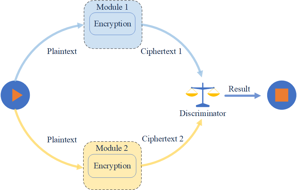
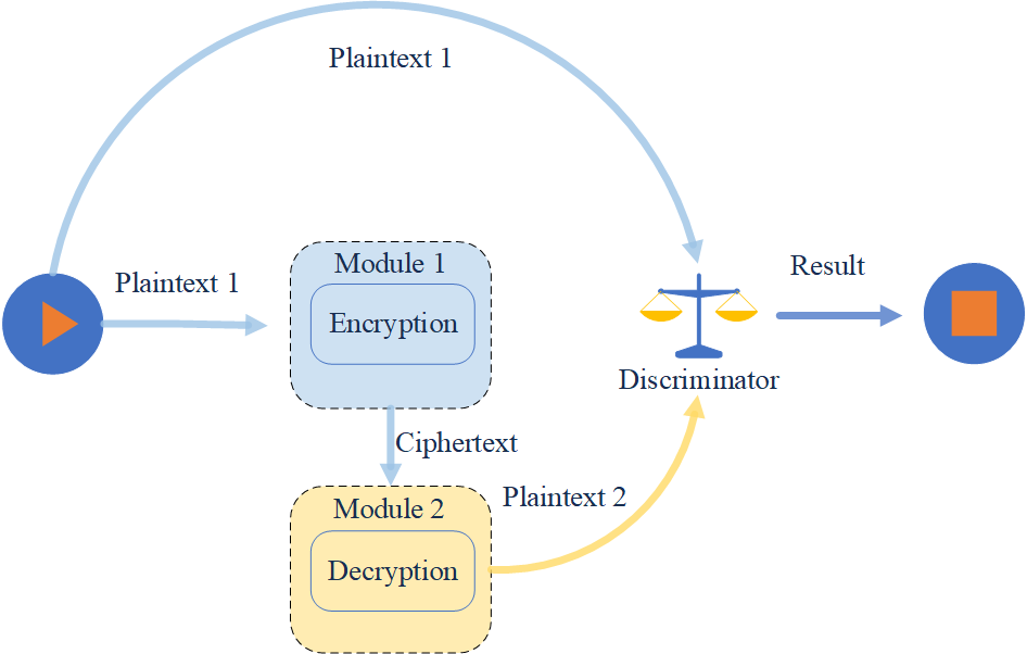
As shown in Fig. 1, the DMR scheme uses two modules to perform cryptographic operations. It is called as Redundant Encryption based DMR (REDMR) if module 1 and module 2 both perform encryption operation. The discriminator of REDMR compares the ciphertexts of two modules in order to detect faults. In contrast, if module 1 performs encryption operation, and module 2 performs decryption operation with the ciphertext of module 1, this situation is named as Inversive Decryption based DMR (IDDMR). The discriminator of IDDMR compares the original plaintext with the plaintext from module 2 to detect faults. Based on the result of discriminator, some defenses can be deployed, such as No Ciphertext Output (NCO), Zero Value Output (ZCO) and Random Ciphertext Output (RCO). Cryptographic devices are forbidden to output ciphertexts with NCO defense. With ZCO defense, the ciphertexts are only composed of zero. And cryptographic device outputs random values as the ciphertexts with RCO defense.
Bytes Scrambling. In addition to detection techniques, another effective countermeasure is to make it hard to make use of faults for the adversary. BS cuts faults out from ciphertexts to shadow the information of faults. Compared with DMR, the advantage of BS is that it has no discriminators and thus cannot be the target of high order FA [30].
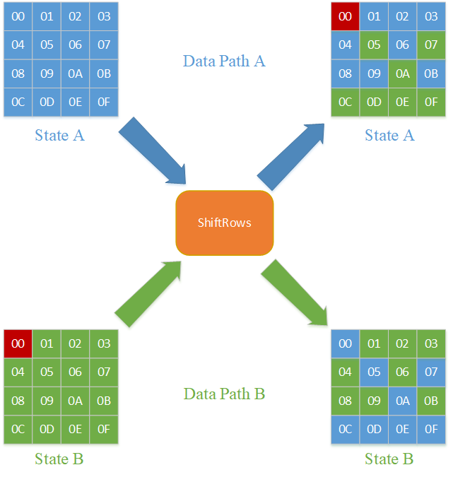
In [24], Joye et al. first applied BS to block cipher and proposed a strengthening hardware AES implementation against FA. The main idea is to use two modules to perform two encryptions in the parallel data path and scramble bytes in the state between the two executions. The ShiftRows operation in AES can be used to perform this scrambling. Note that the adversary is able to inject faults into only one module and observe the ciphertext of this module. We assume that one fault has been injected into the -th byte of the state B before the ShiftRows operation in the last round. As illustrated in Fig. 2, we can see that the half state bytes on data path A (the blue elements) are swapped with their corresponding state bytes on data path B (the green elements) using the special ShiftRows operation. If there are no faults in the two states, the special ShiftRows operation has the same effect as the original ShiftRows operation. However, if there is one fault in state B (the red element), the fault is moved to state A following the ShiftRows operation. As we assumed, the ciphertexts that the adversary observes are correct and any fault analysis of state B is ineffective.
II-C Persistent Fault Attack
As a novel FA method, PFA focuses on the fault which remains between transient and permanent, called persistent fault. In [26], the fault model assumed the affected constant in AES S-box stays faulty unless refreshed, which means the fault can affect several consecutive encryptions.
The core idea of PFA is to perform a statistical analysis of the distribution of each ciphertext candidate. For instance, AES has 256 elements in the S-box. For the -th byte plaintext input, the number of ciphertext candidates is . Because of the avalanche effect, for each ciphertext candidate, the distribution probability is near to when the encryption is correct. For simplification, we ignore the ShiftRows operation because it is a linear process. The ciphertext is composed of the round S-box output and the last round key using bitwise xor, which is equivalent to the following:
| (1) |
For example, suppose that one fault tampers with the element in AES S-box to another element . It leads to the lack of one candidate in the S-box output . The distribution probability of S-box output can be described as follows:
| (2) |
According to Eq.(1) and Eq.(2), the distribution probability of each ciphertext candidate is identical to the S-box output because is fixed, which can be easily represented as:
| (3) |
The process of PFA against the byte key is described as follows. First, the adversary injects persistent faults into the cryptographic device using the laser or other physical methods. Then the adversary encrypts with random plaintexts repeatedly and collects the ciphertexts. With a sufficient number of ciphertexts (generally needs thousands of ciphertexts), the adversary can perform a statistical analysis of the distribution of each ciphertext candidate. According to the result of the theoretical analysis, the candidate with the most number of occurrences and the candidate with the least number of occurrences can be searched to recover the last round key using a simple bubble sort.
It is interesting that every ciphertext candidate is helpful for recovering the last round key , whether it is the most probable, the least probable, or another ciphertext byte value. It is clear that the adversary can recover with and according to Eq.(4) and Eq.(5):
| (4) |
| (5) |
With other ciphertext candidates , the adversary is unable to recover directly. However, the adversary can use these candidates to eliminate impossible candidates of , which can be written as:
| (6) |
Actually, in [26], the authors pointed out that the statistical analysis may produce faulty positives of and (i.e. one of is mistaken for or ) because and can be obviously distinguished from others only when the total number of ciphertexts is sufficient. Therefore, eliminating the impossible candidates may be more effective with a small number of ciphertexts .
It is worth noting that, in practice, the adversary has no prior knowledge of the value of the faulty element in the S-box. In other words, the adversary is unable to distinguish or from all elements in the S-box. However, it does not mean that PFA is impractical. In [27], Zhang et al. solved this problem by adding an extra step to search and before the recovery step. The experimental result demonstrated that the number of ciphertexts to search and is less than the number of ciphertexts to recover . There is no need to collect extra ciphertexts for the search step.
III A Novel Algorithm against PFA
In this section, we introduce a novel algorithm against PFA. First, we provide our fault model and core idea. After that, we describe the process of our algorithm and discuss some details like the time cost analysis and the comparison with other FA countermeasures.
All analysis in this section is aimed for the Single-Byte-Fault scenario. The more complicated Multiple-Bytes-Faults scenario is discussed in Sect. IV.
III-A Fault Model
To prevent PFA, our fault model follows the original PFA fault model in [26], which is as follows:
-
•
The adversary injects persistent faults into the cryptographic device before the encryption.
-
•
The persistent faults randomly corrupt the stored constant (i.e. the S-box table in AES implementation) in the storage of the cryptographic device.
-
•
The persistent faults persist for some time until the storage is refreshed or the device is reboot.
-
•
The adversary is able to use the faulty device to encrypt random plaintexts and collect ciphertexts for subsequent analysis.
III-B Core Idea
The core idea of our algorithm is to keep the correctness of all ciphertexts. As a matter of fact, the successful fault injection does not mean that the FA is successful. The information which the adversary can directly exploit to recover the key exists in the faulty ciphertexts. If the encryption does not access the faulty element in the S-box, the round computation and the ciphertexts will be correct. Such correct ciphertexts are useless for the adversary. If the adversary is unable to collect enough number of the faulty ciphertexts, PFA will be failed.
To this end, our algorithm is composed of three stages. In the first stage, we propose a fast-detection mechanism to detect the existence of the fault in each element in the S-box. If the fault is detected, a fault-correction mechanism is set up to correct the fault and ensure the correctness of ciphertexts in the second stage. The fault-correction mechanism makes use of the relationship between the adjacent elements in the S-box to build extra redundant tables. Using these redundant tables, the algorithm can correct the faulty elements in the S-box. In the final stage, the cryptographic device encrypts with the plaintexts and produces the correct ciphertexts. The details of the two mechanisms are described below.
III-C The Fast-Detection Mechanism
The Detection Mechanism Using the SubBytes Module. According to the fault model, the fault is injected into the storage so as to corrupt the elements in the S-box. A simple detection solution is to traverse all the elements in the S-box to detect faults. Due to excessive overhead, we tend to utilize available resources more than a new detection module. Based on the modular design, the four operations in the process of AES encryption (AddRoundKey, SubBytes, ShiftRows and MixColumns) can be divided into four standalone modules. Fortunately, the SubBytes module can be used to detect faults because it uses S-box to produce the outputs. Note that the output of the S-box is fixed with a fixed input. On account of the length of the plaintext is 16 bytes, the SubBytes module of AES can only access at most 16 elements in the S-box in each iteration. Therefore, the detection mechanism can only detect at most 16 elements in the S-box in each iteration.
A trivial method is inputting all elements in the S-box into the SubBytes module and prestoring the correct outputs. The detection mechanism compares the calculations of the module with prestored values to detect the fault. However, this method requires to prestore pairs of fixed inputs and outputs. And the comparison needs to be repeated 16 times. The cost of this method is excessive thus we need to find a new way to detect the fault more effectively.
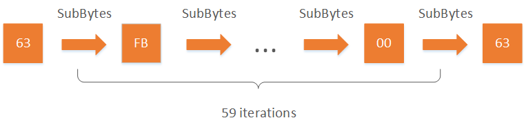
Improvement with the Closed Loop. To improve the detection mechanism, we tend to find one pair of fixed input and output that can detect all elements in the S-box. For this purpose, we introduce a concept termed closed loop. If the output of the SubBytes module after a few iterations is equal to the initial input, all elements used in the SubBytes module are in the same closed loop. Fig. 3 shows a closed loop in AES S-box with 59 elements. Note that different loops have different lengths. We make the following assumptions:
-
•
There are elements in the S-box of the cryptographic algorithm.
-
•
All elements in the S-box are assigned to closed loops. The length of the -th closed loop can be denoted as .
-
•
The length of the input of the SubBytes module is . With a fixed input, the SubBytes module can access all elements in the S-box after iterations.
Therefore, the fixed input needs to be constructed skillfully. Let denote the number of bytes in the input which is distributed to the -th closed loop. Let denote the minimal iteration times the SubBytes module requires to traverse all elements of the -th closed loop, which can be calculated as:
| (7) |
According to the bucket theory, the iteration time depends on the maxinum of , which can be described as:
| (8) |
To accelerate the detection mechanism, we need to minimize the iteration time with the constraint condition . The best solution is to make the iteration of each closed loop near. Thus the set of can be calculated as:
| (9) | ||||
The Fast-Detection Mechanism of AES S-box. Our detection method is described as follows:
-
(1)
We construct one pair of fixed input and output which is processed in the SubBytes.
-
(2)
We process the input in the SubBytes. After iterations, the SubBytes module can access all elements in the S-box and generate the output .
-
(3)
We compare with . If , the fault is detected.
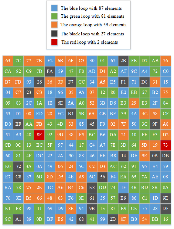
As shown in Fig. 4, the elements of different loops in AES S-box are marked with different colors. There are five closed loops in AES S-box. The longest loop (the blue loop) has 87 elements, and the shortest loop (the red loop) has only 2 elements. Thus, the fixed input and output that constructed in our fast-detection mechanism are shown in Fig. 5.
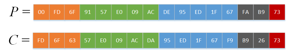
The minimum number of iterations of each loop is 20, 17, 18, 11, and 2, respectively. Consequently, we set the minimum number of iterations to 20 to guarantee that each element in the S-box is detected. Then the fixed output can be calculated and shown in Fig. 5 as well. Because the number of iterations is minimum on the whole, the detection mechanism reaches the fastest speed in our approach.
However,the shortest loop is a special case. Note that the byte of this loop in both fixed input and output are the same. If a fault is able to alter the output of the element 73 to itself, the fixed input and output in Fig. 5 is unable to detect this fault. In fact, the adversary has no ability to inject targeted faults under the current technology conditions. Even assuming that the adversary has this ability, we can calculate another fixed output after 21 iterations. With and , the two elements in the shortest loop can be detected meanwhile.
III-D The Fault-Correction Mechanism
Once the fault is detected by the fast-detection mechanism, the fault-correction mechanism is designed to correct faults and ensure the correctness of ciphertexts. As described in Sect. II, two redundant modules are demonstrated that they can detect the fault. We plan to correct the fault with redundant modules as well. However, two redundant modules are unable to correct the fault because the discriminator in the DMR is unable to distinguish which output is correct. If we use more than two redundant modules, the number of the correct outputs is more than the number of the faulty outputs. To guarantee the correctness of the output of the discriminator, we can add a new rule that the minority should follow the majority.
An existing redundant resource is the adjacencies of each element in the S-box. In the S-box based on look-up table, each element has four adjacencies in four directions (up, down, left and right). Thus the S-box is able to provide 4 times redundancy which is enough to correct the fault. However, in the S-box, one element is hard to be calculated by its adjacencies directly. We need to build a relationship between the adjacent elements by the bitwise xor computation to achieve this goal.
In this subsection, we use to denote the element in AES S-box, which is in row , column . Respectively, we use , , and to denote four adjacencies of . And the bitwise xor computation results between and its adjacencies can be denoted as , , and , respectively. Take the up direction as an example, the relationship among , and can be described as follows:
| (10) |
The other directions are similar to Eq.(10). We store all bitwise xor computation results in the four directions as four redundant tables respectively. Then the fault-correction mechanism can correct according to Eq.(11):
| (11) |
The correction results in Eq.(11) are with different superscripts, as there are probably some faulty elements in the S-box that lead to faults in the correction results. If there is one faulty element in the S-box, it alters one of the four correction results , , and . However, the discriminator can select the majority of the correction results as the final output .
Note that in the horizontal direction, of is identical with of . In the vertical direction, of is identical with of as well. Based on this observation, we can condense the four redundant tables in the four directions to two redundant tables in the horizontal and vertical directions. When we correct the adjacent elements, we only need to change the sequential order of elements in the redundant tables.
its adjacencies
its adjacencies
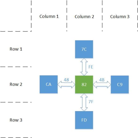
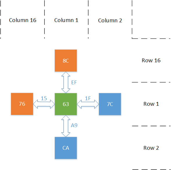
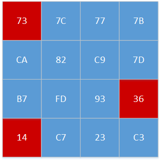
Fig. 6 shows two cases in AES S-box. The most common case is shown in Fig. 6a. The green element 82 has four blue adjacencies. Then we can obtain four bitwise xor computation results to build the redundant tables. Another special case for the peripheral elements is shown in Fig. 6b. The green element 63 is in row 1, column 1. It only has two blue adjacencies in the right and down directions. To solve this problem, we connect the S-box table end to end in the horizontal and vertical directions. Row 1 is on the bottom of row 16, and column 1 is on the right side of column 16. As shown in Fig. 6b, two orange elements are used to make up the adjacencies of the green element 63.
III-E Time Cost Analysis
In this subsection, we analyse the time cost on the basis of our algorithm. In addition, we compare our algorithm with the other two FA countermeasures which are introduced in Sect. II. For simplicity, we only consider the case that the operations are performed serially.
Recall the process of AES encryption. Each transformation round consists of four different operations. And an extra KeyExpansions operation is used to generate the round key from the master key. Let , , , and denote the time cost of the five different operations (AddRoundKey, SubBytes, ShiftRows, MixColumns and KeyExpansions) respectively. Let denote the time cost of the original AES encryption. We can easily deduce the following:
| (12) |
Focus on our algorithm. Compared with the original AES algorithm, the detection mechanism and the fault-correct mechanism are the additional cost. Let and denote the time cost of the two mechanisms respectively. In fact, the essence of the detection mechanism is performing the SubBytes operation 20 times, so can be described as:
| (13) |
On the other hand, the size of depends on the correction range of the fault-correction mechanism. If the fault-correction mechanism only corrects the fault element in the S-box, four bitwise xor computations will be performed. If the correction range of the fault-correction mechanism is the full S-box, the number of bitwise xor computations is equal to . As the AddRoundKey operation contains 16 bitwise xor computations, can be denoted as:
| (14) |
Let denote the time cost of our algorithm. It can be easily computed as the sum of , and . So can be deduced as follows:
| (15) | ||||
As mentioned in Sect. II, the two FA countermeasures — DMR and BS both need two modules to perform AES encryption independently. So the time cost of the two FA countermeasures is double the original AES. Let and denote the time cost of DMR and BS respectively, we can denote as:
| (16) | ||||
For the sake of comparison, let denote the unit of the time cost. We assume that is equal to . Actually, in [31], the authors pointed out that there are significant differences among the time cost of different operations. , and are approximately equal. is approximately equal to double the sum of , and . And is approximately equal to a quarter of . To sum up, is the maximal time computation and can be considered as the minimal time cost in AES encryption. Then the time cost of our algorithm and the two other FA countermeasures can be written as:
| (17) | ||||
In conclusion, even in the most complex case, our algorithm has less time cost than the two other FA countermeasures. Moreover, in the best case, the time cost of our algorithm is nearly 40% lower than the two other FA countermeasures.
IV Improved Algorithm against Multiple Faults
In this section, we show the performance of our algorithm in the Multiple-Bytes-Faults scenario. Unlike the Single-Byte-Fault scenario, depending on the positions of the faulty elements, the fault model can be divided into the best case, the average case and the worst case. In different cases, the performance of our algorithm is distinct. However, by repeating the process of correction, our algorithm has the potential to correct the faulty elements in the S-box even in the worst case.
Each case is discussed in a separate subsection. In each subsection, we describe the fault positions first. Then we discuss the performance of our algorithm and update the security mechanism to correct the faulty elements in the S-box.
IV-A The Best Case
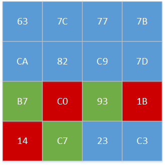
Fault Positions. In the best case, each element in the S-box has at most one faulty adjacency. As shown in Fig. 7a, the positions of the red faulty elements are random and scattered.
Performance. According to the description in subsection III-D, one faulty element only leads to one faulty correction result. As each element has four adjacencies, the majority of the correction results are not changed. The discriminator can keep the output correct in the end.
Update. As the fault-correction mechanism is not affected by the multiple faults in the best case. We do not need to update the security mechanism.
IV-B The Average Case
Fault Positions. In the average case, each element in the S-box has at most two faulty adjacencies. As shown in Fig. 7b, the blue correct elements have at most one faulty adjacency as before. However, each green element has two faulty adjacencies.
Performance. It is a challenge for our algorithm to correct the green elements. Half of the correction results of the green elements are still correct. However, the other faulty half may impact the output in the end. Focus on the green element B7 or C7 in Fig. 7b. The faulty correction results of the element are different. Then the output of discriminator keeps correct because the majority of the correction results are correct.
Worse yet, focus on the green element 93. The faulty correction results of the element are the same. The discriminator can not distinguish which output is correct.
Update. There are two ways to update our security mechanism. A straightforward way is to add the adjacencies of each element. In the broad sense, considering the diagonal directions, each element has eight adjacencies at most. More adjacencies supply more redundancies. The two faulty adjacencies can not impact the output, since the faulty correction results are the minority in all cases.
The other way is repeating the process of correction. Actually, repeating the process of correction twice is enough in the average case. In the first correction, the adjacencies of the green elements are corrected. After the first correction, the average case is the same as the best case. Then in the second correction, the green elements are corrected with the correct adjacencies. Finally, the discriminator keeps the output correct.
IV-C The Worst Case
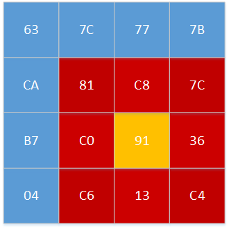
Fault Positions. In the worst case, the faulty elements gather in a large area of the S-box. As shown in Fig. 7c, the red elements and the yellow element are faulty at the same time. Actually, this type of case might seem unlikely. However, if the adversary increases the pulse-width of the laser in the fault injection phase, a large area of elements in the S-box can be affected together.
Performance. For the red elements which have two faulty adjacencies, the performance analysis is identical to the average case. Nevertheless, for the yellow element, all its adjacencies and itself are faulty. So that there are not any more redundancies that can be used in the fault-correction mechanism. There is no way to correct the faulty element in one correction.
Update. Even adding the adjacencies is ineffective. We can still update our security mechanism by repeating the process of correction. The effect of this method depends on the number and position of the fault elements. However, too many faults might be not beneficial to the adversary, we discuss this situation in Sect. VI.
V Practical Implementation
To ensure the practicability and repeatability of our algorithm, we conduct experiments with AES in both software and hardware implementations. In this section, we introduce the experimental targets in the first place. Then we show the experimental details and results. Specially, we improve our algorithm using the pre-correction mode in order to reduce the cost of the hardware implementation.
V-A Target Devices
We use two different targets in our experiments. The software implementation of AES is placed in C, and the hardware implementation of AES is placed in FPGA. The C is the STM32F103 development board with an ARM Cortex-M3 core. The FPGA is the DE2-115 development board with a Cyclone IV 4CE115F29 core. The two targets are common and widely-available so that other researchers can reproduce our work easily. The details of the targets hardware can be seen in Table I.
| Device | Core | Clock Speed | SRAM Size |
|---|---|---|---|
| STM32F103 | ARM Cortex-M3 | 72MHz | 96KB |
| DE2-115 | Cyclone IV 4CE115F29 | 50MHz | 2MB |
V-B Experiments in the Software AES Implementations
On the STM32F103 development board, we run four kinds of AES implementation in both Single-Byte-Fault and Multiple-Bytes-Faults scenarios. All of them are written in C. The first kind of AES implementation called Ori-AES is the original AES without any countermeasures against FA. Then the DMR-AES is the AES which is protected by the REDMR countermeasure with ZCO defense. The third AES implementation named BS-AES is the AES which is protected by the BS countermeasure using the special ShiftRows operation in the last round. In the end, the D&C-AES refers to the AES which is protected by our fast-detection and fault-correction algorithm.
| Implementation | FI detection | Countermeasure | Time Cost () |
|---|---|---|---|
| Ori-AES | No | N/A | 100 |
| DMR-AES | Yes | DMR-ZCO | 200 |
| BS-AES | No | Bytes scrambling | 200 |
| D&C-AES | Yes | Our algorithm | 120.25 184 |
We use the same description as in subsection III-E to denote the unit of the time cost. As shown in Table II, the Ori-AES is the simplest implementation and costs 100 . The DMR-AES and the BS-AES have double cost than the Ori-AES because they need two independent modules to work together. Compared with the others, the cost of our D&C-AES is 120.25 184 . The extra cost of the D&C-AES only involves the detection mechanism and the correction mechanism. We demonstrated above that the two extra mechanisms have lower cost than an extra AES module in the DMR-AES and the BS-AES.
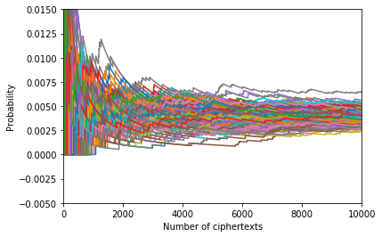
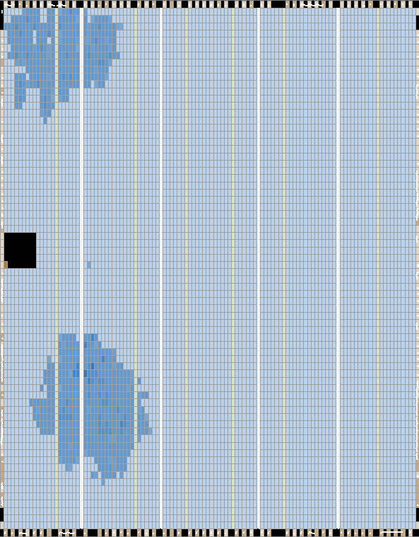
The experimental details are as follows. For each implementation, we instruct the device to perform AES encryption in both Single-Byte-Fault and Multiple-Bytes-Faults scenarios with a 16 bytes random plaintext. We repeat the encryption 10000 times and collect the ciphertexts. In the Multiple-Bytes-Faults scenario, we randomly choose two elements in AES S-box to be corrupted to two random values. The experimental results are shown in Fig. 8 and Fig. 9. The probability for each ciphertext value is plotted as one curve, which is calculated as the counts of appearances for that specific value divided by the number of ciphertexts already used in the experiments. For each implementation, we repeat PFA 1000 times on different datasets. The final attack results with the minimum number of ciphertexts are shown in Table III.
| Implementation | Ciphertext Numbers |
|---|---|
| Ori-AES | 913 |
| DMR-AES | 2007 |
| BS-AES | 1162 |
| D&C-AES | N/A∗ |
none of 16 key bytes were recovered during our experiments
We consider the Single-Byte-Fault scenario first. For the Ori-AES in Fig. 8a, we can observe that two curves do not converge on the probability . As our analysis in subsection II-C, the higher purple curve represents the ciphertext value whose probability is approximately . And the lower green curve represents the ciphertext value whose probability is always zero. This confirms that the original AES is vulnerable to PFA. Table III shows that the minimum number of ciphertexts to recover the key of Ori-AES implementation is 913.
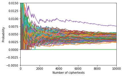
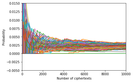
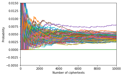
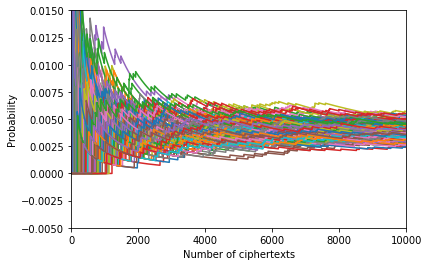
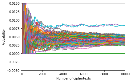
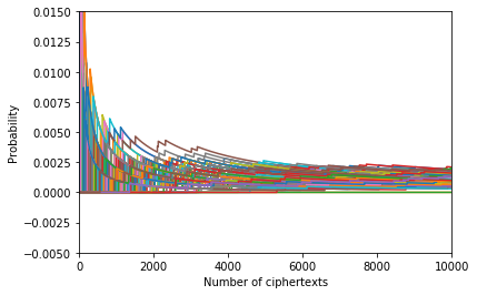
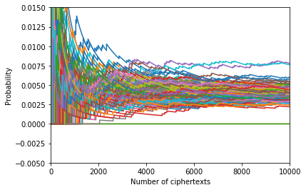
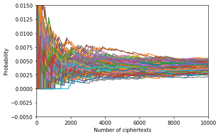
Fig. 8b shows the effect of the DMR countermeasure against PFA. Owing to the ZCO defense, each curve converges to a slightly smaller probability than . The improvement is that the curve of converges to the majority anew. However, the curve of still remains. The adversary can recover the key with Eq.(4) using 2007 ciphertexts at least.
The BS-AES implementation has a poor performance in our experiments. As Fig. 8c shows, this classical FA countermeasure has little effect on preventing PFA. It has a similar distribution probability of ciphertext values as the Ori-AES implementation. Actually, the minimum number of ciphertexts to recover the key is 1162, which is slightly more than the Ori-AES implementation. This is because that BS is directed at the transient fault and should be placed after the fault disappears. In our experiments, the fault is persistent and does not disappear until the device reboots. As a result, BS is unable to protect the ciphertext effectively.
The experimental result of our algorithm is shown in Fig. 8d. Unlike the other three AES software implementations, all curves of our D&C-AES implementation converge on the probability . Table III shows that PFA can not recover the key with all ten thousand ciphertexts, which is well in excess of the requirements of the attack in [26]. It demonstrates that our algorithm can completely prevent PFA in the Single-Byte-Fault scenario.
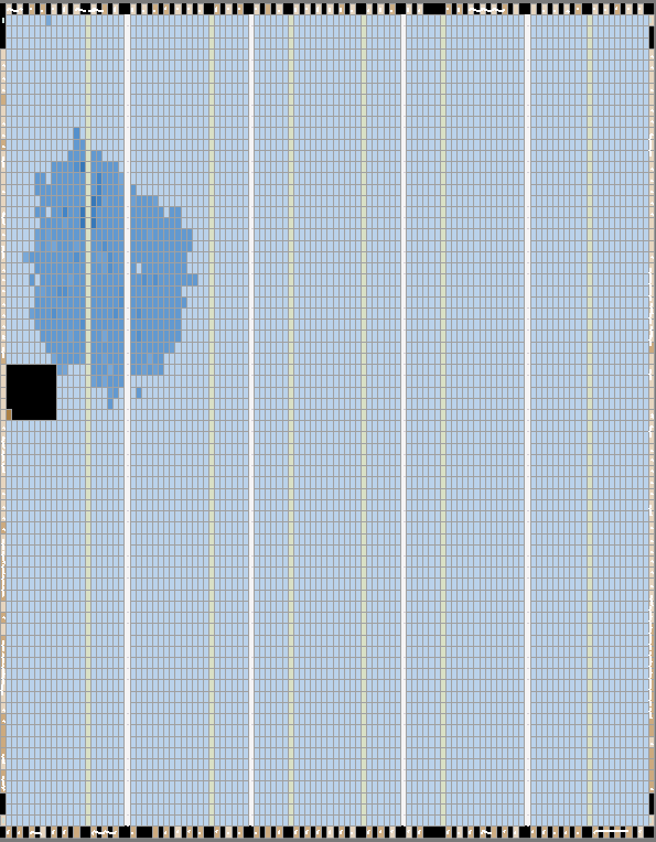
As the comparison with the Single-Byte-Fault scenario, the experimental results in the Multiple-Bytes-Faults scenario are shown in Fig. 9. Different from the Single-Byte-Fault scenario, two curves are higher than the majority in Fig. 9a and Fig. 9c. The reason is that two faults in the S-box lead to the abnormal probabilities of four ciphertext values (two probabilities rise to and two probabilities drop to 0). For the first three implementations, if the adversary wants to recover the key as before, he needs to expand PFA to the penultimate round of AES.
For our D&C-AES implementation, the result in Fig. 9d is as good as before. Note that there are only two random faults in our experiments, which is corresponding to the best case or the average case in Sect. IV. With the increase of the number of faults, our D&C-AES implementation can not ensure the convergence for every curve. Fig. 10 shows the distributions of ciphertext values in the worst case with eight random faults. It is observed that the performance of our D&C-AES implementation is far worse than before. However, it might be hard for adversary to recover the key using PFA as well. The relationship between the performance of PFA and the number of faults is discussed in Sect. VI.
V-C Experiments in the Hardware AES Implementations
The experimental details in the hardware AES implementations are quite similar to that in the software AES implementations. And the experimental results are consistent with those shown in Fig. 8 and Fig. 9. The Ori-AES and the BS-AES are vulnerable to PFA. The DMR-AES with ZCO defense can prevent PFA which is based on . However, the adversary can still recover the key using . Compared with the other three AES implementations, our D&C-AES has the best effect and can prevent PFA effectively.
However, unlike C, FPGA requires the designer to implement the design not at the algorithm level but at the circuit level. The cost of the area and the internal resources must be considered.
In subsection V-B, our D&C AES implementation puts the detection mechanism and the correction mechanism before the encryption. It is reasonable in C because of its serial nature. However, compared with the computation, implementing the circulation is more challenging and resource-intensive in FPGA. As there are a mount of circulations in the detection mechanism, we change our algorithm from the D&C mode to a simplified pre-correction mode to reduce the cost. In the pre-correction mode, we remove the detection mechanism and integrate the correction mechanism with the SubBytes operation. The function of S-box table is replaced with the horizontal and vertical redundant tables which are used in the correction mechanism. The output of the correction mechanism is used as the output of the SubBytes operation.
The area cost of the D&C and the pre-correction implementations is shown in Fig. 11. Table IV shows the cost of the internal resources of those two implementations. The cost of the pre-correction implementation is about half of the D&C implementation. This can be boiled down to that the pre-correction implementation reduces the cost of the detection mechanism and the S-box table.
| Implementation | LUTs | Registers |
|---|---|---|
| D&C | 10505 | 403 |
| Pre-correction | 6438 | 268 |
VI Discussions
We demonstrate the effectiveness of our algorithm in both software and hardware implementations in the previous section. In this section, some problems are discussed besides our algorithm itself. We discuss the relationship between the performance of PFA and the number of faults firstly. Then, we make a comparison between our algorithm and TMR. Finally, the expansibility of our algorithm is open to discussion.
VI-A PFA with Multiple Faults
In Sect. IV, we find that with the increase of the faulty elements, it is increasingly challenging for our algorithm to correct the fault. However, the adversary is not necessarily benefited from the Multiple-Bytes-Faults scenario. In [26], the authors pointed out that the multiple faults increase the number of ciphertexts required in PFA. If there are faults in the S-box, the remaining key candidates can be at most reduced to . The adversary has to try brute force of the remaining key candidates. Therefore, if there are too many faulty elements in AES S-box, it is also a challenge for the adversary.
VI-B Comparing Our Algorithm with TMR
In subsection III-D, our fast-detection mechanism corrects faults with the majority voting calculation. This design is similar to TMR, which is another well-known FA countermeasure. However, using two redundant tables, our algorithm can provide four times redundancy but TMR can only provide double redundancy. Besides, since TMR uses more redundant modules than DMR, the time cost of TMR is higher than DMR as well. As mentioned in subsection III-E, our algorithm has less time cost than DMR. Thus, our algorithm is more effective than TMR.
VI-C Extending Algorithm to Prevent Other FA Methods
Since our algorithm prevents the attacker to collect faulty ciphertexts, those FA methods which require faulty ciphertexts are ineffective. Take DFA as an example. The adversary compares the differences between correct ciphertexts and faulty ciphertexts to recover the key. In [32], the authors proposed a new DFA on block cipher with S-box. Their fault model assumed the adversary has the capability to inject a Single-Byte-Fault into S-box and collect correct/faulty ciphertexts. This assumption does not make sense with our algorithm because all ciphertexts are correct.
VII Conclusion
In this paper, we propose a fast-detection and fault-correction algorithm against PFA. The strength of our algorithm is that it can completely prevent PFA by correcting the S-box element fault in the Single-Byte-Fault scenario. Further, in the Multiple-Bytes-Faults scenario, our algorithm also has good performance. The experimental results in both software and hardware implementations ensure the practicability and repeatability of our algorithm. Compared with the classical FA countermeasures like DMR and BS, our algorithm is more effective and has less time cost.
Our correction mechanism can be easily transplanted to the encryption algorithms based on Substitution-Permutation Network (SPN), such as LED or PRESENT. However, there are also some encryption algorithms, such as RSA or ECC, with different structures. It is a challenging future work to design the correction mechanism for those encryption algorithms.
Acknowledgment
The authors would like to thank Information Science Laboratory Center of USTC for the hardware/software services. This work was supported by National Natural Science Foundation of China (Nos. 61632013, 61972370 and 62002335), and Fundamental Research Funds for Central Universities in China (No. WK3480000007).
References
- [1] D. H. Habing, “The use of lasers to simulate radiation-induced transients in semiconductor devices and circuits,” IEEE Transactions on Nuclear Science, vol. 12, no. 5, pp. 91–100, 1965.
- [2] D. Boneh, R. A. DeMillo, and R. J. Lipton, “On the Importance of Checking Cryptographic Protocols for Faults,” in Advances in Cryptology — EUROCRYPT ’97. Springer Berlin Heidelberg, 1997, pp. 37–51.
- [3] I. Biehl, B. Meyer, and V. Müller, “Differential fault attacks on elliptic curve cryptosystems,” in Annual International Cryptology Conference. Springer, 2000, pp. 131–146.
- [4] G. Piret and J.-J. Quisquater, “A differential fault attack technique against spn structures, with application to the aes and khazad,” in International workshop on cryptographic hardware and embedded systems. Springer, 2003, pp. 77–88.
- [5] G. Wang and S. Wang, “Differential fault analysis on present key schedule,” in 2010 International Conference on Computational Intelligence and Security. IEEE, 2010, pp. 362–366.
- [6] P. Jovanovic, M. Kreuzer, and I. Polian, “A fault attack on the led block cipher,” in International Workshop on Constructive Side-Channel Analysis and Secure Design. Springer, 2012, pp. 120–134.
- [7] F. Amiel, C. Clavier, and M. Tunstall, “Fault analysis of dpa-resistant algorithms,” in International Workshop on Fault Diagnosis and Tolerance in Cryptography. Springer, 2006, pp. 223–236.
- [8] J.-M. Schmidt and M. Hutter, Optical and EM Fault-Attacks on CRT-based RSA: Concrete Results. na, 2007.
- [9] S. Govindavajhala and A. W. Appel, “Using memory errors to attack a virtual machine,” in 2003 Symposium on Security and Privacy, 2003. IEEE, 2003, pp. 154–165.
- [10] S. P. Skorobogatov, “Semi-invasive attacks: a new approach to hardware security analysis,” 2005.
- [11] R. Torrance and D. James, “The state-of-the-art in ic reverse engineering,” in International Workshop on Cryptographic Hardware and Embedded Systems. Springer, 2009, pp. 363–381.
- [12] S. P. Skorobogatov and R. J. Anderson, “Optical fault induction attacks,” in International workshop on cryptographic hardware and embedded systems. Springer, 2002, pp. 2–12.
- [13] F. Courbon, P. Loubet-Moundi, J. J. Fournier, and A. Tria, “Adjusting laser injections for fully controlled faults,” in International workshop on constructive side-channel analysis and secure design. Springer, 2014, pp. 229–242.
- [14] N. Selmane, S. Guilley, and J.-L. Danger, “Practical setup time violation attacks on aes,” in 2008 Seventh European Dependable Computing Conference. IEEE, 2008, pp. 91–96.
- [15] G. Canivet, P. Maistri, R. Leveugle, J. Clédière, F. Valette, and M. Renaudin, “Glitch and laser fault attacks onto a secure aes implementation on a sram-based fpga,” Journal of cryptology, vol. 24, no. 2, pp. 247–268, 2011.
- [16] E. Biham and A. Shamir, “Differential fault analysis of secret key cryptosystems,” in Annual international cryptology conference. Springer, 1997, pp. 513–525.
- [17] T. Fuhr, E. Jaulmes, V. Lomné, and A. Thillard, “Fault attacks on aes with faulty ciphertexts only,” in 2013 Workshop on Fault Diagnosis and Tolerance in Cryptography. IEEE, 2013, pp. 108–118.
- [18] C. Clavier, “Secret external encodings do not prevent transient fault analysis,” in International Workshop on Cryptographic Hardware and Embedded Systems. Springer, 2007, pp. 181–194.
- [19] C. Dobraunig, M. Eichlseder, T. Korak, S. Mangard, F. Mendel, and R. Primas, “Sifa: exploiting ineffective fault inductions on symmetric cryptography,” IACR Transactions on Cryptographic Hardware and Embedded Systems, pp. 547–572, 2018.
- [20] E. Böhl and M. Ihle, “A fault attack robust trng,” in 2012 IEEE 18th International On-Line Testing Symposium (IOLTS). IEEE, 2012, pp. 114–117.
- [21] C. Deshpande, B. Yuce, N. F. Ghalaty, D. Ganta, P. Schaumont, and L. Nazhandali, “A configurable and lightweight timing monitor for fault attack detection,” in 2016 IEEE Computer Society Annual Symposium on VLSI (ISVLSI). IEEE, 2016, pp. 461–466.
- [22] L. Zussa, A. Dehbaoui, K. Tobich, J.-M. Dutertre, P. Maurine, L. Guillaume-Sage, J. Clediere, and A. Tria, “Efficiency of a glitch detector against electromagnetic fault injection,” in 2014 Design, Automation & Test in Europe Conference & Exhibition (DATE). IEEE, 2014, pp. 1–6.
- [23] H. Bar-El, H. Choukri, D. Naccache, M. Tunstall, and C. Whelan, “The sorcerer’s apprentice guide to fault attacks,” Proceedings of the IEEE, vol. 94, no. 2, pp. 370–382, 2006.
- [24] M. Joye, P. Manet, and J.-B. Rigaud, “Strengthening hardware aes implementations against fault attacks.” IET Information Security, vol. 1, no. 3, pp. 106–110, 2007.
- [25] M. Karpovsky, K. J. Kulikowski, and A. Taubin, “Robust protection against fault-injection attacks on smart cards implementing the advanced encryption standard,” in International Conference on Dependable Systems and Networks, 2004. IEEE, 2004, pp. 93–101.
- [26] F. Zhang, X. Lou, X. Zhao, S. Bhasin, W. He, R. Ding, S. Qureshi, and K. Ren, “Persistent fault analysis on block ciphers,” IACR Transactions on Cryptographic Hardware and Embedded Systems, pp. 150–172, 2018.
- [27] F. Zhang, Y. Zhang, H. Jiang, X. Zhu, S. Bhasin, X. Zhao, Z. Liu, D. Gu, and K. Ren, “Persistent fault attack in practice,” IACR Transactions on Cryptographic Hardware and Embedded Systems, pp. 172–195, 2020.
- [28] J. Pan, F. Zhang, K. Ren, and S. Bhasin, “One fault is all it needs: breaking higher-order masking with persistent fault analysis,” in 2019 Design, Automation & Test in Europe Conference & Exhibition (DATE). IEEE, 2019, pp. 1–6.
- [29] M. Dworkin, B. Barker, J. Nechvatal, J. Foti, L. Bassham, E. Roback, and J. Dray Jr, “Advanced encryption standard (aes)(nist fips–197),” 2001.
- [30] C. H. Kim and J.-J. Quisquater, “Fault attacks for crt based rsa: New attacks, new results, and new countermeasures,” in IFIP International Workshop on Information Security Theory and Practices. Springer, 2007, pp. 215–228.
- [31] S. Mangard, E. Oswald, and T. Popp, Power analysis attacks: Revealing the secrets of smart cards. Springer Science & Business Media, 2008, vol. 31.
- [32] K. Jeong, J. Sung, S. Hong, and C. Lee, “A new approach of differential fault analysis on block ciphers with s-box,” International Information Institute (Tokyo). Information, vol. 16, no. 3, p. 1915, 2013.