format-include-endings=true, group-citation=true, list-style=tabular \DeclareAcronymCDTshort = DTF, long = digital twin framework \DeclareAcronymDTMCshort = DTMC, long = discrete\Hyphdashtime Markov chain \DeclareAcronymLTSshort = LTS, long = labelled transition system \DeclareAcronymMDPshort = MDP, long = Markov decision process, long-plural=es \DeclareAcronymPCTLshort = PCTL, long = probabilistic computation tree logic \DeclareAcronympDTMCshort = pDTMC, long = parametric \acDTMC \DeclareAcronympGCLshort = pGCL, long = probabilistic guarded command language
Verified Synthesis of Optimal Safety Controllers for Human-Robot Collaboration††thanks: This research has received funding from the Assuring Autonomy International Programme (AAIP grant CSI: Cobot), a partnership between Lloyd’s Register Foundation and the University of York, and from the UKRI project EP/V026747/1 ‘Trustworthy Autonomous Systems Node in Resilience’.
Abstract
We present a tool-supported approach for the synthesis, verification and validation of the control software responsible for the safety of the human-robot interaction in manufacturing processes that use collaborative robots. In human-robot collaboration, software-based safety controllers are used to improve operational safety, e.g., by triggering shutdown mechanisms or emergency stops to avoid accidents. Complex robotic tasks and increasingly close human-robot interaction pose new challenges to controller developers and certification authorities. Key among these challenges is the need to assure the correctness of safety controllers under explicit (and preferably weak) assumptions. Our controller synthesis, verification and validation approach is informed by the process, risk analysis, and relevant safety regulations for the target application. Controllers are selected from a design space of feasible controllers according to a set of optimality criteria, are formally verified against correctness criteria, and are translated into executable code and validated in a digital twin. The resulting controller can detect the occurrence of hazards, move the process into a safe state, and, in certain circumstances, return the process to an operational state from which it can resume its original task. We show the effectiveness of our software engineering approach through a case study involving the development of a safety controller for a manufacturing work cell equipped with a collaborative robot.
Keywords risk-informed controller synthesis formal verification probabilistic model checking code generation collaborative robot safety digital twins
1 Introduction
Effective collaboration between humans and robots [Nicolaisen1985-OccupationalSafetyIndustrial, Jones1986-StudySafetyProduction] can leverage their complementary skills. But such collaboration is difficult to achieve because of uncontrolled hazards and because sensing, tracking, and safety measures are either still unexploited in practice [Santis2008-atlasphysicalhumanrobot] or they are difficult to validate following state-of-the-art safety regulations [Chemweno2020-Orientingsafetyassurance]. Since the 1980s, remote programming (also called tele\Hyphdashprogramming) and simulation have led to some reduction of hazard exposure. However, the effectiveness of human-robot collaboration is still limited because of frequent conservative shutdowns, simplistic emergency stops, and unspecific error handling procedures. Extensive guarding arrangements interfere with manufacturing processes and mobile robot applications. But effective work processes and complex tasks require continuous close human-robot interaction (e.g. mutual take-over of tasks), mutual clarification of intent, and trading off risk [Hayes2013-ChallengesSharedEnvironment, Villani2018-Surveyhumanrobotcollaboration]. From an operator’s perspective, robot movements need to be predictable, and potential impacts on the human body need to be attenuated. From a control perspective, the confident monitoring and control of the robot speed and the separation between machines and humans require high-quality stereo vision and laser scanners to distinguish several safety zones. A decade after these issues were discussed in Alami2006-Safedependablephysical and Haddadin2009-RequirementsSafeRobots, Ajoudani2017-Progressprospectshumanrobot emphasise that the complex safety challenges of collaborative robots (cobots for short, Gillespie2001-generalframeworkcobot) remain largely unresolved. Increasingly complex robotic systems reduce the ability to understand and mitigate risks. Safety is a major barrier to the more widespread adoption of cobots, with organisations such as manufacturers having to resort to sub-optimal processes due to safety concerns. Methods of ensuring safe human-robot interaction will deliver $7.3bn of savings, reducing costs of US-manufactured goods by 1% [Anderson2016-EconomicImpactTechnology]. However, little such method and tool support is available for engineers that have to implement and confidently assure cobot safety requirements, that is, the results of cobot hazard analyses and risk assessments [Chemweno2020-Orientingsafetyassurance].
Problem.
Among the measures for improving cobot safety, the monitoring of application processes, the handling of critical events, and the mitigation of operational risk are the responsibility of software\Hyphdashbased safety controllers. To facilitate smooth human-robot collaboration with minimal interruption, the software engineers responsible for developing these controllers need to closely consider the process with its variety and complexity of adverse events, such as unusual operator behaviour and equipment failure modes. This leads to complex requirements and design spaces for the safety controllers, so these engineers must address questions in several areas:
-
1.
Risk assessment. Which controller minimises the probability of incidents in the presence of human and sensor errors?
-
2.
Controller synthesis. Which design minimises nuisance to the human, maximises productivity, etc. while maintaining safety?
-
3.
Controller verification. Does a controller handle hazards when detected and return the system to a useful safe state?
-
4.
Controller validation. Does an implementation of the synthesised controller exhibit the intended behaviour?
Preliminary solution.
In Gleirscher2020-SafetyControllerSynthesis, we provide initial answers to the first three questions, by introducing a preliminary software engineering approach for the synthesis of discrete\Hyphdashevent safety controllers that meet safety requirements and optimise process performance in human-robot collaboration. We model the application (e.g. a manufacturing process) as a \acMDP, and select correct\Hyphdashby\Hyphdashconstruction controllers from an associated design space. The process model describes the behaviour of all involved actors including the controller. To describe critical events (e.g. hazards) and controller actions (e.g. safety mode changes), we employ the notion of risk structures [Gleirscher2017-FVAV, Gleirscher2021-RiskStructuresDesign] implemented in the risk-informed controller designer Yap [Gleirscher-YapManual, Gleirscher2020-YAPToolSupport] used for risk structuring, qualitative risk analysis, and synthesis of risk-informed safety controllers. In particular, Yap supports risk modelling and controller design with a domain-specific language and automates the transformation of risk structures into guarded command language and, in turn, \acpMDP. The preliminary approach from Gleirscher2020-SafetyControllerSynthesis facilitates the verification of the safety of the \acMDP and of probabilistic reach-avoid properties of selected \acMDP policies including the controller. A verified controller extracted from such a policy detects hazards and controls their mitigation by the execution of a safety function, a transition to a particular safety mode, or a safer process task or activity. Furthermore, in certain circumstances, the controller returns the process to an operational state from which it can resume its original task.
Contributions.
In this paper, we extend our preliminary software engineering approach for safety controller synthesis [Gleirscher2020-SafetyControllerSynthesis, Gleirscher2020-YAPToolSupport] with multiple new capabilities, and we overcome several of its limitations, as explained below.
We refine the process and risk modelling to enable the synthesis of finer-grained controllers. For this, we provide a refined factor notion in Section 4.2.1. We improve and extend the verification stage by checking additional properties, increasing the confidence in the synthesised controllers. We employ the stochastic model synthesis tool evoChecker [Gerasimou2018-Synthesisprobabilisticmodels] in addition to the probabilistic model checker Prism [Kwiatkowska2011-PRISM4Verification], extending the verification capabilities of the optimal synthesis procedure to significantly more complex combinations of controller requirements.
We translate the controllers into executable code for a \acCDT to foster controller validation in a realistic environment. We assure the correctness of this translation by reusing properties from model checking in run-time verification. The \acCDT validation of the safety controller is based on randomised use-case tests that satisfy well-defined state-based coverage criteria.
We demonstrate in the \acCDT how the synthesised safety controller can automatically resume the nominal procedure after the mitigation of hazards. We provide experimental results that confirm our safety controller’s ability to achieve an increased process utility in addition to ensuring high levels of freedom from accidents.
Overall, we increase the level of technical detail, to improve the understanding and reproducibility of our results. Section 2 introduces our case study as a running example, and Section 3 provides the theoretical background. We describe our process modelling and controller design method in Section 4, our approach to verified optimal synthesis in Section 5, and explain in Section 6 how we implement, deploy, and validate the synthesised controllers in a realistic purpose built digital twin. We evaluate and discuss our approach in Section 7. Section 8 highlights related work. We conclude with a short summary in Section 9.
2 Running Example: Manufacturing Cobots
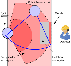
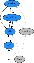
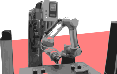
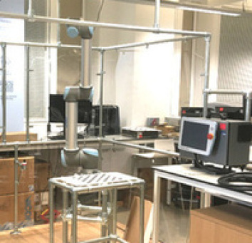
Figure 2 shows a cobot-equipped manufacturing work cell at a UK company (with the pictures anonymised for confidentiality reasons) and replicated in a testbed at the University of Sheffield (Figure 2c). In the corresponding process, , an operator, a stationary collaborative robotic manipulator (robot arm for short), and a spot welder (Figure 1a) collaborate repetitively on several activities (Figure 1b).111For the sake of simplicity, we use the notion of an activity as a hypernym describing a task, a situation, a use case, or a scenario. Previous safety analysis (i.e., hazard identification, risk assessment, and requirements derivation) resulted in two sensors. The first one is a range finder using a rotating laser beam (indicated with the highlighted area at the bottom of Figure 2a) to determine the distance between the spot welder and a person or an object intruding into the highlighted area and triggering a slow down or an emergency stop if the intruder approaches the spot welder. The second one is a light barrier (the highlighted curtain indicated in Figure 2b) triggering such a stop if something like a person’s arm reaches across the workbench while the robot or the spot welder are active. Table 1 shows our partial safety analysis of the cell following the guidance in Section 1. The right column specifies safety goals against each accident and controller requirement candidates (e.g. mode-switch requirements) handling each latent cause in the left column, and indicating how the hazard is to be removed. The running example is part of a case study organised around the AAIP project CSI: Cobot.222See https://www.sheffield.ac.uk/sheffieldrobotics/about/csi-cobot. Due to Covid-19 restrictions limiting access to physical facilities during a critical phase of the project, we use a digital twin of the work cell as a target platform to deploy and validate synthesised safety controllers.
| Id | Critical Event (risk factor) | Safety Requirement |
|---|---|---|
| Accident (to be prevented or alleviated) | Safety Goal | |
| The Robot arm harshly Collides with an operator. | The robot shall avoid harsh active collisions with the operator. | |
| Welding Sparks cause operator injuries (skin burns). | The welding process shall reduce sparks injuring the operator. | |
| The Robot arm Touches the operator. | The robot shall avoid active contact with the operator. | |
| Latent Cause (to be mitigated timely)† | Controller Requirement‡ | |
| The Human operator and the Robot use the Workbench at the same time. | (m) The robot shall perform an appropriate mitigation (e.g. a safety-rated monitored stop) and (r) resume normal operation after the operator has left the shared workbench. | |
| The Human operator is entering the Workbench while the robot is away from the workbench. | (m) If the robot moves a workpiece to the workbench then it shall switch to power & force limiting mode and (r) resume normal operation after the operator has left the workbench. | |
| The Human operator has entered the Safeguarded area while the robot or the spot welder are active. | (m) The spot welder shall be switched off, the robot to speed & separation monitoring, and the operator be notified to leave. (r) Robot and spot welder shall resume normal mode after the operator has left. | |
| The Human operator is Close to the welding spot while the robot is working and the spot welder is active. | (m) The spot welder shall be switched off, the robot to safety-rated monitored stop. (r) Both shall resume normal or idle mode with a reset procedure after the operator has left. | |
| †m: mitigation requirement, r: resumption requirement, ‡subjected to generalisation to define a controller design space | ||
3 Background
This section summarises the background of the presented approach, particularly, cobot safety, probabilistic model checking, system safety analysis, and risk-informed controller modelling.
3.1 Robot Safety: From Industrial to Collaborative
| Stage | Type of Measure | Examples |
| Hazard prevention | 1. Safeguard/barrier | Fence, cage, interlock |
| 2. IT safety | Verified† safety controller | |
| 3. IT security | Security-verified† (safety) controller | |
| Hazard mitigation & accident prevention | 4. Reliability | Fault-tolerant scene interpretation |
| 5. Workspace intrusion detection | Speed & separation monitoring, safety-rated monitored stop | |
| 6. Shift of control | Hand-guided operation | |
| Accident mitigation (alleviation) | 7. Power & force limitation | Low weight parts, flexible surfaces; variable impedance, touch-sensitive, & force-feedback control |
| 8. System halt | Emergency stop, dead-man’s switch | |
| †avoidance of development or programming mistakes | ||
Hazards from robots have been studied since the advent of industrial robotics in the 1970s, resulting in risk taxonomies based on workspaces, tasks, and human body regions [Sugimoto1977-SafetyEngineeringIndustrial, Jones1986-StudySafetyProduction, Alami2006-Safedependablephysical, Haddadin2009-RequirementsSafeRobots, Wang2017-Humanrobotcollaborativeassembly, Kaiser2018-SafetyRelatedRisks, Matthias2011-Safetycollaborativeindustrial, Marvel2015-CharacterizingTaskBased]. The majority of hazards are impact hazards (e.g. unexpected movement, reach beyond area, dangerous workpieces, hazardous manipulation), trapping hazards (e.g. operator locked in cage), and failing equipment (e.g. valve, cable, sensor, controller). In the 1980s, robots were programmed interactively by operators being in the cage while powered, which had caused frequent accidents from trapping and collision. However, from the late 1990s on, the increased use of tele-programming contributed to the reduction of accidents related to such hazards.
Addressing hazards outside the programming stage involves the examination of each mode of operation (e.g. normal, maintenance) for its hazardous behaviour, and the use of safety controllers to trigger mode-specific safety measures [Jones1986-StudySafetyProduction]. Malfunction diagnostics (e.g. fault detection, wear-out monitoring) can further inform these controllers. Table 2 shows a variety of measures [Santis2008-atlasphysicalhumanrobot] to prevent or mitigate hazards and accidents by reducing the probability of the occurrence and the severity of the consequences of these hazards. If these measures use electronic or mechatronic equipment, we speak of functional333 Functional safety (see IEC 61508, ISO 26262) deals with the dependability, particularly, correctness and reliability, of critical programmable electronic systems. Safety functions or “functional measures” are the archetype of such systems. measures (e.g. safety modes as exemplified below) and of intrinsic measures otherwise (e.g. a fence around a robot, flexible robot surfaces). Functional measures focusing on the correctness and reliability of a controller (a programmable electronic or software system) are called dependability measures [Alami2006-Safedependablephysical, Avizienis2004-Basicconceptstaxonomy]. Functional measures are said to be passive if they focus on severity reduction (e.g. force-feedback control), active otherwise. In this work, we focus on the verified synthesis [kress-gazit_synthesis_2018] of safety controllers that realise active functional safety measures.
Standardisation of safety requirements for industrial robots [Sugimoto1977-SafetyEngineeringIndustrial] culminated in ANSI/RIA R15.06, ISO10218, 13482, and 15066. Following ISO 10218, such robot systems comprise a robot arm, a robot controller, an end\Hyphdasheffector, and a work piece (see, e.g. Figure 1a). According to Helms2002-robatworkRobotassistant and Kaiser2018-SafetyRelatedRisks, one can distinguish four scenarios of human-robot interaction: (i) Encapsulation in a fenced robot work space, (ii) co\Hyphdashexistence without fencing but separation of human and robot work space, (iii) cooperation with alternative exclusive use of shared work space, and (iv) collaboration with simultaneous use of shared work space and close interaction. Cooperation and collaboration are the two most interactive of these scenarios and motivate our work. In collaborative operation, the operator and the cobot [Gillespie2001-generalframeworkcobot] can occupy the collaborative workspace simultaneously while the cobot is performing tasks [ISO15066, Pt. 3.1]. The collaborative workspace has to be a subset of the safeguarded workspace.
Based on these definitions, ISO 15066 recommends four safety modes. First, a safety-rated monitored stop is an active functional measure realised as a mode where the robot is still powered but there is no simultaneous activity of the robot and the operator in the shared workspace. Second, hand-guided operation refers to a mode with zero-gravity control, that is, control without actuation beyond the compensation of gravity, solely guided by an operator. Hand guidance requires the robot to be in a compliant state, with control exerted by the operator through physical manipulation. Third, speed & separation monitoring as an active functional measure refers to a mode where speed is continuously adapted to the distance of the robot and an operator. Forth, power & force limiting is a mode with reduced impact of the robot on the human body and the robot’s power and applied forces are limited. In this mode, a robot should not impact a human with more than a defined force, with acceptable forces mapped out for different impact points on the body. Heinzmann2003-QuantitativeSafetyGuarantees propose such a mode always active during a collaborative activity described as a discrete-event controller. Long2018-industrialsecuritysystem propose a distance-triggered scheme to switch between nominal (max. velocity), reduced (speed limiting), and passive (hand-guided) operating modes. Kaiser2018-SafetyRelatedRisks and Villani2018-Surveyhumanrobotcollaboration describe and combine these modes with work layouts.
In addition to these safety modes, Alami2006-Safedependablephysical highlight the necessity of a general shift from robots whose motion is controlled only by following a pre-specified route of positions (also known as position control) to robots whose motion control minimises contact forces and energy (also known as interaction control). Overall, interaction\Hyphdashcontrolled robots, with less pre-planning and fewer assumptions on workspace structure and robot actions, can exploit the mentioned safety modes more effectively than position-controlled robots with extensive pre-planning and stronger assumptions.
3.2 Probabilistic Model Checking and Trace Checking
The proposed approach employs \acpMDP, and corresponding sets of \acpDTMC, as a formal model of the process , and uses the policy space of an \acMDP, describing the degrees of freedom for decision making, to model the design space for verified controller synthesis.
Definition 1.
MDP. Given all distributions over a sort (e.g. an action alphabet of a process ), an \acMDP is a tuple with a set of states, an initial state , a probabilistic transition function , and a map labelling with atomic propositions [Kwiatkowska2007-StochasticModelChecking].
Given a map , signifies non-deterministic choice in . Choice resolution for forms a policy.
Definition 2.
Policy. A policy is a map s.t. . is deterministic if .
In this paper, we restrict our self to the consideration of deterministic policies.444More precisely, we only consider memoryless policies, with some restrictions on \acMDP policy synthesis, however, not relevant for our purposes. Let be the space of all such policies for . Then, action rewards defined by a map allow the comparison of policies in based on a quantity .
Verification of can be done using \acPCTL whose properties over are formed by
with ; an optional bound for with ; the quantification operators to verify (or with , to quantify) probabilities, and to determine long-run probabilities of an atomic proposition .555With and , we denote optional and alternative syntactic choice in sub- or superscript language elements. is also a mandatory notational element to encapsulate a formula following a temporal operator. States correspond to valuations of state variables of type , , or . Hence, propositions in are of the form for a variable and a function (or constant) . We use the abbreviations , , , and . The \acPCTL extension calculates reachability rewards () and (optionally bounded) accumulative action rewards (). With (), we state that the \acMDP from state (the state ) satisfies the property . Let denote the largest subset with for a state predicate .
For the checking of a recorded trace of a system, we use fragments of linear and metric temporal logic whose properties over are formed by the propositional fragment as defined above and by , , and , with a finite interval . Comprehensive treatments of \acPCTL, linear and metric temporal logic can be found in, for example, Kwiatkowska2007-StochasticModelChecking, Basin2015-MonitoringMetricFirst and Baier2008-PrinciplesModelChecking.
The concise construction of , the behaviour of , can be facilitated by using a flavour of \acpGCL, for example, as implemented in the Prism tool [Kwiatkowska2007-StochasticModelChecking, Kwiatkowska2011-PRISM4Verification]. Guarded commands have the form with an event (or action) label and a probabilistic update applicable to only if , where is an expression in the propositional fragment of \acPCTL.666We use to separate guard and update expressions and both for logical implication and the definition of mappings. With for probabilistic choice and to compose assignments, general updates are defined as with and being a multiple assignment to state variables based on functions .
3.3 Risk Modelling for Controller Design
We view an application (e.g. Section 2) as a process, , monitored and influenced by a safety controller to mitigate hazards and prevent accidents. Critical events, such as accidents (or mishaps), their causes, and causal factors (e.g. hazards), are state properties. We express these properties as subsets of . In particular, mishaps are undesired states (e.g. all states where a person is injured by welding sparks). For a mishap , we further define a subset from which is reachable, for example, all states in where the operator is near the spot welder while the latter is active. We call the causes of . Causes are intersections of causal factors, in particular, factors related to the subject of protection (e.g. the operator to be protected by the safety controller when being near the spot welder) and a hazard as a causal factor related to the system (e.g. the spot welder being active; Leveson1995-SafewareSystemSafety, Leveson2012-EngineeringSaferWorld). We call causes latent or controllable777As opposed to immediate causes with limited or no risk handling controls. if there are sufficient resources to prevent the accident (e.g. time for removing by transition to ). Controllability can be justified, for example, by assuming that if the spark flow is low there is a small time span left for the spot welder to be stopped or the operator to leave without leading to an accident. can also refer to states in being critical because certain events (e.g. an operator approaches the spot welder) cause a transition to , and possibly , if stays active, further conditions hold, and no safety measures are put in place promptly. Below, in Section 4.2.1, we will use state propositions to identify the discussed critical events.
Based on these notions, risk modelling can be facilitated by specifying risk factors and combining them into risk structures [Gleirscher2021-RiskStructuresDesign]. A risk factor is a \acLTS modelling the life cycle of a critical event in terms of phases. In its basic form, has the phases inactive (), active (), mitigated (), and mishap (). Transitions between these phases signify endangerment events () as well as mitigation () and resumption () actions. A risk structure from a factor set (e.g. column Id in Table 1) operates over a risk (state) space with . Furthermore, let be the set of states labelled with at least one cause, describing the abstract state where any critical event has at least been sensed by the controller (e.g. with its handling about to start, i.e., the controller transitioning from to ). We call the non-accident -unsafe region. One can hypothesise relationships between critical events using factor dependencies. Such relationships can be identified and justified by, for example, a hazard operability study, a failure mode effects analysis, or a fault tree analysis. Further details about risk structures will be introduced along with our approach explained below in Section 4.
3.4 Digital Twins
We focus on digital twins as a platform for controller deployment and validation. Digital twinning is a key Industry 4.0 technology for enabling industrial automation, smart processes, and process autonomy [Negri2017, Bolton2018]. Together with the Internet of Things and machine-to-machine communication, digital twinning enables both the creation of a better data infrastructure and the adoption of smart manufacturing technologies. A digital twin provides greater access to data relating to, and control over, a physical system, and has particular value in the design, implementation, and evaluation of processes and safety controllers.
Kritzinger2018 and Tao2018digital define a digital twin as:
“A digital twin is an integrated multi-physics, multi-scale, probabilistic simulation of a complex product and uses the best available physical models, sensor updates, etc., to mirror the life of its corresponding twin.”

More specifically, a digital twin is a digital representation of a physical system that operates in parallel888A digital twin must be able to operate synchronously with the physical system, but asynchronous operation is also permissible. with the real system. This concurrency can persist throughout the life-cycle of the physical system. Communication between the physical twin and its digital representation is bilateral, and as a result, both can be mutually informed by real-world or simulated sensor data, requested actions and decisions. As a means for safety verification and analysis, a digital twin presents: (i) A faithful representation of the process domain and state space, (ii) a means to interrogate and collect data that may not be readily available from the physical system (independent of hardware limitations), and (iii) an interface to the physical twin through which real-world responses to new safety procedures can be demonstrated.
4 Modelling for the Synthesis of Safety Controllers
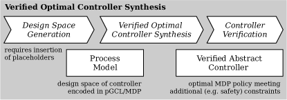
Figure 3 provides an overview of the proposed approach to the synthesis of safety controllers. The main idea is that the control engineer designs a safety controller on top of an application, in this instance, comprising activities where humans and robots collaborate. The intention of the deployed controller is to increase safety with respect to the critical events under consideration.
In the modelling stage, the control engineer creates several models to obtain a design space including controller candidates to select from during synthesis. When modelling the process of the application, the engineer as a domain expert describes the actions performed by any of the actors in the application. The engineer then performs a risk analysis resulting in a risk model that informs the process model with a notion of operational risk. The abstraction chosen for the model and a usual lack of knowledge about process details require the integration of stochasticity and performance estimates into the model. With the risk- and performance-informed stochastic process model, the engineer can specify controller behaviour in form of a mitigation model. In the controller synthesis stage, an abstract controller is automatically synthesised from the design space according to risk- and performance-based optimality criteria. Finally, in the deployment and validation stage, this controller is translated automatically into an executable form. The three stages are supported by the tools Yap, Prism, evoChecker, and the \aclCDT. These stages are detailed in the following sub-sections and illustrated with several examples from our case study introduced in Section 2.
4.1 Modelling Processes
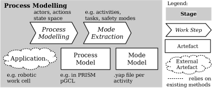
For process modelling (Figure 4), we use \acpGCL to specify the actions of the process. The process model defines the state space to be manipulated by these actions and includes the actions of the cobot and the environment including human operators. We group actions into activities as abstractions of the process. Activities describe certain tasks and facilitate the transition to risk modelling by structuring hazard identification and the creation of a hazard list. The mode model resulting from this abstraction step is an abstract \acLTS.
We describe the process, , as a set of guarded commands, distinguishing actions of relevant actors (e.g. a robot arm, a spot welder, an operator) and the safety controller from events of a sensor module and shared “manipulables” (e.g. workpiece support). Following Section 3.2, the structure of the guarded commands describing the behaviour in follows the pattern
with an action label , an action-specific condition and a generic update (see Section 3.2) being part of the overall guard and update expressions. The state space is built from discrete variables (cf. LABEL:lst:statespace) capturing the world state (e.g. robot location, workbench status), sensory inputs (e.g. range finder), control outputs (e.g. robot behaviour, notifications), user inputs (e.g. start button), and modes (e.g. activities, safety modes).
4.1.1 Process Execution from a Controller’s Perspective
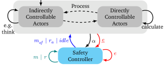
To account for the interaction of the safety controller with the process, we include a fair cyclic execution scheme into the process model. This scheme emulates the simultaneity of the controller and the process. Execution steps alternate between the controller and a set of actors, ensuring in each cycle that each actor can take its turn (Figure 5). Regarding the way the controller can influence the process, we distinguish between directly controllable actors (e.g. cobot, spot welder) and indirectly or not controllable actors (e.g. human operator). Both kinds of actors can perform logical and physical actions following two corresponding command patterns:
| (logical action) | ||||
| (physical action) |
where guards the turn of an actor and stores the token passed between the safety controller and the other actors. denotes the safety controller’s turn. can include a condition for terminating execution when reaching a final (or goal) state, resulting in . The controller can stay idle or, most eagerly, intervene whenever one of the actors has completed an action. This scheme is more restrictive than the CSP-style999Following the synchronous interleaving semantics of Hoare’s Communicating Sequential Processes. generalised parallel composition of concurrent processes available by default in tools such as Prism [Kwiatkowska2011-PRISM4Verification].
4.1.2 Modelling Activities and Safety Modes
To facilitate the design of a powerful class of safety controllers, we organise actions (e.g. grab work piece, move robot arm to spot welder) of ’s controllable actors using mode variables, here, one variable for the engagement of each actor in an activity (e.g. ract) and one for the safety mode of the whole process (safmod). Mode variables group actions and, from a controller perspective, allow high-level process control by filtering enabled actions. Thus, the structure of the guarded commands for is refined according to the pattern
where guards the enabling of actions in certain activities (e.g. exchange work piece, Figure 1b) and in certain safety modes (e.g. speed & separation monitoring). We obtain safety- and task-aware actions by conjoining . The update of is optional to combine certain actor-internal updates into atomic actions.
The following listing describes part of the enumerations used to define the discrete state space of .
The following commands specify two actions, r_moveToTable and r_grabLeftWorkpiece, for the actor robotArm in the activity exchWrkp.
4.2 Modelling Risk
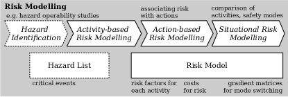
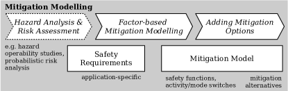
For our synthesis approach to lead to correct and effective controllers, we need an expressive risk model (Figure 6). To obtain such a model, we translate the hazard list into a set of risk factors (Section 4.2.1). For this, we transcribe safety analysis results into factor \acpLTS (Section 3.3). Then, we define a risk profile for each of the process actions (Section 4.2.1). For each hazard in the hazard list, the risk profile of an action describes the risk that a performance of the action results in an accident related to this hazard. The final step of risk modelling consists of capturing risk-related situational change (i.e., a change of activity or safety mode) in the process with a risk gradient (Section 4.2.2). For this, we associate a numerical measure with each activity transition (i.e., each situational change), that describes the change in overall risk level. We proceed analogously with the definition of safety modes and the corresponding risk assessment.
4.2.1 Refined Risk Factors
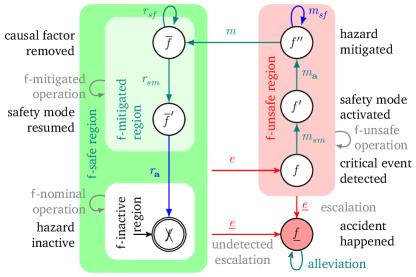
Shown in Figure 7, we develop and use a refinement of the notion of a risk factor introduced in Section 3.3. As before, for a factor , we refer to any state of where is inactive as the -inactive region or, equivalently, as . Any state of where has occurred and any causal factor is still active is subsumed by the -unsafe region, which includes three phases: hazard detected (), safety mode activated (), and hazard mitigated (). The -mitigated region refers to any state deviating from ’s nominal state but with any causal factor of removed. The -mitigated region includes the phase , reached when causal factors of have been removed, and , reached after deactivating a safety function and resuming from the current safety mode. The phases , , and together constitute the -safe region of .
When a critical event is detected in the -safe region, is switched to . For a critical event, we distinguish its ground truth predicate (i.e., the cause) from the detector (or monitoring) predicate (i.e., the sensor) where in case of perfect sensing. Critical event detection follows the pattern
where is a relevance indicator determining whether to react on in an activity or, more generally, in a particular situation. With , we ignore re-occurrences while is active or after an accident. Idling of the safety controller (Figure 5) is captured by
where passes the token from the actor to the next actor in (Figure 5). The other actions will be explained in Section 4.4.
Activity-based Risk.
Factor \acpLTS guide the formalisation of hazards, their causes, and mishaps and the events in the causal chain (e.g. a mishap event leads to a mishap state). This way, factors support the design of mitigations to reduce accidents, and alleviations to reduce consequences. Hence, all critical events related to an activity should be translated into a factor set.
Action-based Risk.
We define an action multi-reward structure over to measure overall and factor-specific risk in . Action rewards are guarded, requiring being active. For example, if then is active in state .
4.2.2 Situational Risk
The decision space of the safety controller for mitigations and resumptions includes choices from sets of safety modes () and activities () to switch to from a particular mode and activity. To simplify the design space in , we resolve this choice during generation (Section 5.1) using a categorical risk gradient . For categorical variables , we allow the convention denoting the change of when changes its value from to .
We implement with two skew-diagonal matrices and , assuming that they can be (manually) derived from safety analysis based on the following justification. Assume that, in the activities , actors vary in physical movement, force, and speed. If means more or wider movement, higher force application, or higher speed than in , then a change from to will likely reduce risk. Hence, . Similarly, assume that the safety modes vary ’s capabilities by relaxing or restricting the range and behavioural shape of the permitted actions. If relaxes capabilities more than , then a change from to will likely reduce risk. Again, . Skew-diagonality of the matrices provides that . The matrices for can be specified as part of a Yap model.
We instantiate according to Figure 7 for the hazard from Table 1. When an operator approaches an active spot welder, an event is detected, activating by a transition to a state where the predicate holds, a state in . The safety controller will then start with performing mitigations to reach phase . The handling of includes the switching to a speed & separation monitoring mode, issuing an operator notification, and waiting for the operator’s response. From , the controller can continue with resumptions (e.g. switching from speed & separation monitoring back to normal) to finally return to phase where both and are false. Further endangerments (e.g. erroneous robot movement) may reactivate from phase or . An accident with the spot welder or robot arm, leading to phase , can occur, for example, because of a faulty range finder responsible for the detection of or too slow mitigations and . In , alleviations (e.g. flexible robot surfaces, protective goggles) can reduce certain consequences. We start encoding in a Yap model below.
As a factor dependency, we identify requiresOcc , expressing the assumption that the factor must have occurred prior to the activation of . Using the guard directive, we specify the cause , the ground truth predicate for the activation of . Figure 8 shows the resulting risk structure for our case study as a risk graph.
The risk profile for the robot arm actions and the factors and is encoded in the Yap model in an intuitive and compact manner.
Based on the activity automaton in Figure 1b, we encode in our Yap model with the two distance matrices act and safmod.
4.3 Modelling Stochastic Adversarial Phenomena
In this stage (Figure 9), we integrate adversarial stochastic phenomena into the process model. Probabilistic choice in can be used to model various phenomena, such as accidents, human error, and sensor failure.
Mishaps.
In the refined factor model (Figure 7), a mishap leading to phase is always possible, assumed to happen more likely in the -unsafe region than in the -safe region. Accident-prone physical actions follow the two command patterns:
with the probability of a mishap if the cause of the critical event has occurred, independent of whether or not ’s activation () was detected. and can include specific updates if an accident occurs respectively if it does not. can be inferred from observations, experiments, or accident statistics. We keep using and for action-specific preconditions respectively updates.
Human Error.
A human error model can be informed by hierarchical task analysis [Stanton2006-Hierarchicaltaskanalysis]. We introduce a particular class of human errors into using the pair of probabilistic commands
with a predicate specifying when action is safe or permitted to be performed, the probability of an operator to commit a specific error when this action is not safe or not permitted, and a deontic flag controlling whether the logical action is to be reified into the physical action with a potentially dangerous update .
Sensor Failure.
Informed by a fault tree or failure mode effects analysis, one can consider sensor and actuator faults in a way similar to human error. To model fault behaviour, we employ the pattern
with a probability of a sensor failing to detect a specific event implied by , an update modelling the correct behaviour of the sensor, and an update modelling its failure behaviour.
We model the accident that, with a 20% chance, follows (i.e., remains undetected because of a sensor fault) or (i.e., the safety controller is not reacting timely). For the encoding of , Yap’s input language supports the specification of the actions with the mishap as a bad outcome if is undetected or not mitigated timely, the probability of under these conditions, and the severity of the expected consequences from . Furthermore, we model the human error that, with a 10% chance, the operator enters the cell, knowing that the robotArm and the spotWelder are active. Finally, we specify as a sensor failure that the range finder as the detector of fails in 5% of the cases when the operator enters the cell.
The command patterns explained in this section can be combined, offering many degrees of modelling freedom not further discussed here. For practical examples, see also Gleirscher2020-YAPToolSupport.
4.4 Modelling Mitigations
For mitigation modelling (Figure 10), we complete the factor \acpLTS introduced in Section 4.2.1 with mitigation actions. The ability of stochastic models, such as \acpMDP, to express nondeterminism supports the modelling of alternative mitigation options. To extend the controller design space, we can thus specify several such options for each factor. Differences in the quality of these options (e.g. expected nuisance and effort) can be quantified using reward structures.
The capabilities of actors in determine the controllability of critical events. To restrict the controller design space, we allow three kinds of actions: action filters (i.e., safety modes, cf. Section 1), activity changes (e.g. change from welding to off), and safety functions (e.g. interacting with the operator through warnings). These mitigations are mirrored by corresponding resumptions. We continue with our discussion of how mitigation and resumption actions, according to the refined factor \acLTS in Figure 7, are translated into \acpGCL.
Let be the risk factor under consideration for the rest of this section. Given the ground truth predicate and the corresponding detector predicate for (Section 4.2.1), we assume to have identified a causal factor such that (i.e., an absent causal factor eliminates the cause) and (i.e., the causal factor is detectable). Factor dependencies, such as requiresOcc in Section 4.2.2, can be used to automatically derive part of (cf. Yap, Gleirscher2020-YAPToolSupport).
Let a mitigation option for with a target activity , a target safety mode , and picked from a set of safety functions. For each combination possible in a state , the controller provides a safety mode switch
and an activity switch
where and are determined according to the scheme
| (3) |
We use the non-strict order because a switch to a desired target within the same risk level should be allowed. Then, the controller activates a safety function through the commands
Reaching phase constitutes the first set of logical controller actions. The performance of these actions is followed by an interaction with the process. If this interaction results in the elimination of , the controller finalises the mitigation stage with the command
The controller subsequently moves into the resumption stage, continuing with the deactivation of the safety function through
and the resumption from the current to a more progressive safety mode from any risk state by
Beyond its basic enabling condition (), the controller checks whether both the cause of the critical event and, particularly, the causal factor subject of mitigation have been removed ().
Analogously, the resumption of the current activity to a more productive activity from any risk state is accomplished with
Given a resumption option and the set of factors active or mitigated in risk state , the reaction of the controller follows the scheme
| (4) |
This scheme determines the most permissive yet allowed combination of activity and safety mode to switch to among all activated or mitigated factors in , that is, the combination with the maximum acceptable risk as seen from and according to .
In order for the controller to be able to safely deal with a factor set , we assume that each of the controller actions is idempotent. Note how phase indicators (e.g. ) ensure that the controller is performing in the right context (e.g. if ). The discussion of alleviations is out of scope of this synthesis approach.
Continuing with LABEL:lst:moving, we specify mitigation actions in our Yap model as shown below for the factor with three mitigation and two resumption options.
The directive detectedBy defines the sensor predicate , stating that “the human operator is in the safeguarded area” (hST_HOinSGA). The factor attribute mitigatedBy associates with three mitigation options, and the attribute resumedBy with two resumption options. For example, in the action HCStOffVis, (i) updatemodels a safety function, issuing a notification to the operator to leave the safeguarded area, and (ii) targetswitches the manufacturing cell to the activity off and to the safety mode stopped,101010In a design variant discussed in Gleirscher2020-SafetyControllerSynthesis, we allow mitigations to synchronise with the robotArm and spotWelder on an event stop. all triggered by the range finder (rngDet=close). The guard and detectedBy attributes are translated into a pair of predicates for , RCE_HC () describing world states, and CE_HC () signifying states monitored by the range finder.
4.5 Modelling Performance
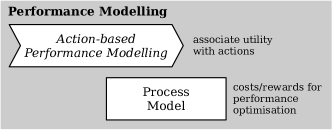
In analogy to the rewards for mitigation actions, in this stage (Figure 11), we quantify performance (e.g. effort, productivity) for all non-controller actions in the process. As a result, optimal policy synthesis from is based on several reward structures quantifying the performance of both the safety controller and the process.
For controller performance, we distinguish mitigation and resumption options by manually estimated quantities such as disruption of the manufacturing process, nuisance of the controller to the operator, and resources (e.g. effort, time) consumed by the controller. We formalise these quantities as action rewards with . As shown in Section 4.5, rewards can depend on parameters other than state variables.
Analogously, concerning process performance, we associate with each process action a productivity measure depending on the safety mode, using an action reward structure .
In a Yap model, mitigation and resumption options can be associated with action rewards:
Note how nuisance depends on the parameter alarmIntensity1 modelling the loudness or brightness of an alarm sound or lamp that can be varied in the search for an optimal controller. Rewards for process actions can be specified in a concise manner in a Yap model.
5 Verified Synthesis of Safety Controllers
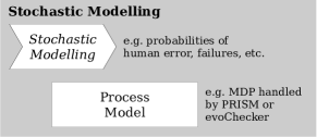
In this stage, we integrate the risk and mitigation models with the process model, resulting in a risk-informed reward-enhanced stochastic model that includes the controller design space in the process decision space (Figure 12). The action sets for the cobot, the operator, and the controller are now combined. With this integrated model, we perform a constrained policy synthesis to select an optimal yet abstract safety controller from the design space. We use constraints to encode the safety requirements and optimisation queries to facilitate this selection. For this to work, we express safety requirements as \acPCTL properties and verify them using a stochastic model checker. We accomplish controller synthesis in two settings.
The \acMDP Setting.
We perform optimal policy synthesis from an \acMDP (using Prism) where the design space is encoded as non-deterministic choice (e.g. among mitigation options). This approach has already been discussed in Gleirscher2020-SafetyControllerSynthesis.
The \acpDTMC Setting.
We perform an evolutionary search (using evoChecker) of a set of \acpDTMC. This set defines the design space by fixing the parameters of a \acpDTMC. This \acpDTMC can be obtained from the original \acMDP by replacing non-deterministic choice with random choice and by introducing the corresponding parameters. In both cases, optimal policy synthesis produces a \acDTMC containing an abstract discrete-event safety controller. The \acpDTMC-based approach avoids the split into two verification stages as previously required in Gleirscher2020-SafetyControllerSynthesis.
The synthesis follows a two-staged search through the controller design space: The first stage focuses on the generation of the guarded commands according to Section 4.4. The gradient (Section 4.2.2) resolves the calculation of risk-minimal control updates for these commands. Reward structures are generated for risk and performance quantification (Section 4.5) in the second stage. Then, a stochastic model checker performs verified policy synthesis for . In Gleirscher2020-SafetyControllerSynthesis, we use as an \acMDP for policy synthesis with Prism [Kwiatkowska2011-PRISM4Verification] and extract a controller from the resulting \acDTMC representing the policy.
Here, we enhance this approach. The flexible CSP-style concurrency of the \acpGCL modules is replaced by a more restrictive alternation (Section 4.1.1) of the process and the safety controller, thereby resembling a closed-loop control scheme. The avoidance of interleaving and synchronous events for modelling real-time phenomena (e.g. sensor faults) results in an \acMDP that does not contain states where process actors and the controller compete in non-deterministic choices. The only choices left are actor-internal choices including the choice to idle and pass the token. As a consequence, we obtain fairness for the controller and a simplification of . Additionally, we interpret as a \acpDTMC rather than an \acMDP. Choice in the safety controller among action options is explicitly controlled through decision parameters.
This scheme results in the removal of non-deterministic choice from the controller and a randomisation of residual choice in . We further improve the way how accidents can happen in . For fine-granular risk and performance quantification, we allow additional design space parameters (e.g. alarm intensity) to be used. We use evoChecker [Gerasimou2018-Synthesisprobabilisticmodels] for the search of optimal controllers in the space of \acpDTMC defined by these parameters. The modelling, analysis, and pre-processing required for the approach in Gleirscher2020-SafetyControllerSynthesis and its enhancement described here are supported by the Yap tool [Gleirscher2020-YAPToolSupport].
5.1 Design Space and Reward Structure Generation
The design space is created by instantiating the command patterns of the generic factor \acLTS in Figure 7. These patterns are used by Algorithm 1 and implemented in Yap. The function CompCmd composes guard and update expressions and integrates these into controller commands compliant with the specifications in Section 4.4. The functions GradUpdM and GradUpdR implement Equation 3 respectively Equation 4 for controlling the updates of safety modes and activities. refers to the set of mitigation options for factor . refers to the set of activity tuples, that is, combinations of activities the actors can be involved at a particular point in time. The other command patterns in Section 4.4 are generated analogously. We omit the corresponding generation functions here. The listing in Section 5.1 shows a fragment of the design space.
pGCL fragment generated for the factor :
LABEL:lst:rewards shows a fragment of the reward structures generated from the Yap model described in the Sections 4.2.1, 4.2.1, and 4.5.
The listing below shows two reward structure fragments, one for risk from an active and one for nuisance.
5.2 Verified Optimal Synthesis
The \acpGCL action system consists of the process (i.e., cobot, welding machine, and operator) and the safety controller generated according to Section 5.1. The policy space includes the controller design space. This action system is expanded into an \acMDP by a probabilistic model checker such as Prism or it is used as a \acpDTMC by evoChecker relying on \acDTMC model checking. Choice in stems from commands (e.g. mitigations, resumptions) simultaneously enabled in a state , yielding multiple policies for and from commands enabled in multiple states, giving rise to a policy for each ordering in which these commands can be chosen.
Controller solutions selected from the design space are subjected to two kinds of requirements. The first are optimisation objectives, such as minimal energy consumption. The second are probabilistic and reward-based constraints for safety (i.e., unlikely reachability of bad states, e.g. accidents below probability threshold; accumulated risk below reward threshold) and response (e.g. timely controller response exceeds probability threshold). Both kinds of requirements are expressed in reward-enhanced, quantitative \acPCTL (Section 3.2).
Optimisation Objectives.
An optimal policy , including the controller decisions, can be selected based on, for example, minimum nuisance or maximum productivity. For that, includes action rewards to quantify controller and process performance (Section 4.5), risk reduction potential (in the MDP setting), and risk based on factors, modes, and activities as explained in Section 4.2.
Constraints.
Constraints are of the form . captures well-formedness,111111Well-formedness refers to the class of properties (see, e.g. Table 3) to be checked to establish basic model validity prior to more interesting correctness properties related to the application under consideration. including properties for the verification of, for example, hazard occurrence and freedom from pre- deadlocks, and properties for the falsification of, for example, that final states must not be initial states. Hazard occurrence fosters our focus on adversarial environments. can help one to simplify model debugging, decrease model size, remove deadlocking states, and reduce vacuity of verification results.
specifies safety-carrying correctness and can include progress, safety, liveness, and reliability properties. For example, we want to verify reach-avoid properties of type ; or that the probability of failure on demand of the controller or the probability of a mishap from any hazard is below a threshold. With , we constrain the search for solutions in the design space to controllers whose mitigation paths from critical events are complete with at least probability . In the \acMDP setting (as explained in Section 5), our model allows the evaluation of freedom from accidents in with
| (5) |
where . For the non-accident -unsafe region (Section 3.3), Equation 5 requires the controller to minimise the probability of mishaps until the -safe region (i.e., ) is reached. aggregates , the arithmetic , and probabilities over . In the \acpDTMC setting, we use the plain quantification operator . Table 3 contains further examples of properties in and to be verified or falsified of .
Verified Synthesis.
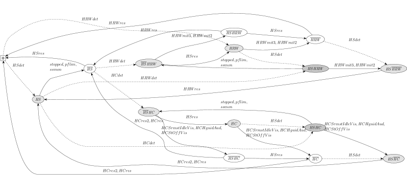
Based on the action rewards from the Sections 4.2.1, 4.2.1, and 4.2.2, the model checker investigates all choice resolutions and parameter valuations for that fulfil well-formedness and further \acPCTL constraints. The checker then identifies policies that fulfil the given constraints and are (Pareto-)optimal with respect to the optimisation objectives. The existence of an optimal strategy depends on the existence of a strategy in that fulfils the \acPCTL constraints. Note that, by Definition 2, all policies considered for are of the same size but may vary in their distribution of choice among the involved actors. The overall result of this step is a verified and optimal abstract controller extracted from the selected policy . An example of such a policy is visualised in Figure 13.
| Property† | Description |
|---|---|
| Optimisation objectives | |
| Assuming an adversarial environment, select that maximally utilises the safety controller. | |
| Select that minimises nuisance up to time . | |
| Objectives with reward-based constraints | |
| Select controller that maximises productivity constrained by risk level and expected severity . | |
| Select controller that maximises productivity constrained by exposure to severe injuries. | |
| Well-formedness constraints in | |
| can finish the production cycle. | |
| can occur during a production cycle. | |
| can deadlock early. (f) | |
| is inevitable. (f) | |
| Some initial states are also final states. (f) | |
| Correctness constraints in | |
| The controller detects for within steps. | |
| The controller timely responds to the belief of .‡ | |
| The controller lively handles hazard . | |
| The controller resumes so it can finish its cycle after has occurred. | |
| Mishap freedom is more likely than . | |
| The steady-state probability of any is below . | |
| † : state with no commands enabled, : end of manufacturing cycle, : initial state of a manufacturing cycle, : mishap state, : probability bound, f: to be falsified, : productivity, : controller effectiveness, : severity, : risk level. ‡We adopt the universality pattern after Dwyer1999-Patternspropertyspecifications using instead of because of the required response; note that we have to use the sensor predicate rather than the ground truth predicate . | |
6 Controller Deployment and Validation
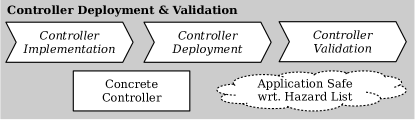
Given the execution semantics of a target platform (e.g. the \aclCDT), the selected controller can now be translated into a concrete executable form (Figure 14) to be deployed, validated, demonstrated, and eventually used on this platform.
6.1 Controller Implementation
The abstract controller, , is part of the calculated policy , a \acDTMC with state space . is a result of combining the risk state space, generated by Yap from the factor set , with the process state space. According to Definition 2, the transition relation of is a list of -tuples. The controller as a deterministic part of is a set of transitions that, at the concrete level, again comprises guarded commands of the form
We use the transition matrix obtained from the model checker (e.g. Prism) to translate controller actions in into concrete actions. Following the four-relation structure of controller models in Parnas1995-FunctionalDocumentationComputer, this step involves (i) the translation of the abstract states into guard conditions based on a mapping of concrete process states into abstract states, and (ii) the translation of the abstract updates into low-level procedures generating control inputs to the process. Figure 15 shows the activation scheme of the concrete controller when deployed on an execution platform. Algorithm 2 describes the corresponding discrete-event SafetyController. According to Figure 5, through 4, the controller is aware of each atomic update of any of the monitored variables.
In our case study, the check of whether in 6 of Algorithm 2 is implemented as a switch statement iterating over all relevant combinations of events known from . The function HandleEvent is responsible for issuing control inputs, such as switching into a power & force limitation mode and notifying the operator to leave the work cell if is activated. The function UpdateRiskState is responsible for managing and remembering the risk state internal to the controller (e.g. state in the mitigation of ). In the supplemental material121212See https://github.com/douthwja01/CSI-artifacts/. for this work, we provide modelling and code examples131313See the hrc2 example of the Yap package (https://github.com/ytzemih/yap). and a video141414See https://youtu.be/cm-XkZ_aitQ. of the controller in action.
Expected Overhead.
The detection and handling overhead is the time elapsed in every cycle of the while loop in Algorithm 2. Let be the processing time required for an action, for example, the calculation of the detection of in . If implemented as part of a sequential cell controller, 6 requires a time slot of length in each control cycle. If 6 is monitored simultaneously in dedicated safety controller hardware, the slowest detection rate for is . The overhead for handling in 7 can be estimated from Figure 7 and may range from to with a repetition factor . The overhead of the implementation in Algorithm 2 can be obtained by recording timed event traces from an execution platform (e.g. the \acCDT). In order for the controller to interact with such a platform, the Yap model is extended by an interface specification in addition to the model fragments discussed in the previous sections. This interface is discussed in more detail in the following section.
6.2 Controller Deployment
Section 3.4 introduces the notion of actors within a collaborative manufacturing setting involving a cobot and an operator (see Figure 16). We are able to reconstruct this setting in the form of a digital twin using our \aclCDT. The \acCDT is a toolchain developed in C# and visualised in Unity3D that provides the kinematic, communication, and data infrastructure necessary to deploy digital twins on real world systems 151515See https://github.com/douthwja01/CSI-artifacts/JSS/.. Using the \acCDT APIs for the MATLAB® robotics toolbox and the Robotic Operating System framework161616See https://www.ros.org., the safety controller’s actions are exchanged with the physical platform in real-time where a response is demonstrated.
We represent the scenario with as an aggregation of actions and decisions made by each actor. Actors may then be identified as (i) digital twins—actors with a distinct collection of models, state-machines and behaviours that emulate the capabilities of the physical system—and (ii) abstractactors without physical embodiment that may provide a service, communicate with or control other actors. The term environment will be used to describe this complete set of actors.
Process Representation.
Let be the set of all actors. Examining the process from a network perspective allows us to model an actor as a communication node, similar to the robotic operating system framework. Following terminology in Broy2010-LogicalBasisComponent, the actor is able to communicate with other nodes through an interface . Here, and denote the subscription (or input) and publication (or output) channels of actor respectively. This decentralised structure allows us to represent a process controller as abstract actor with known feedback and command channels and respectively. The process controller is modelled as a state machine that responds to feedback from actor and issues a requested action on .
Each sensor present in the process is similarly introduced as a digital twin actor . Here, data originating from the sensing capabilities of are broadcast to assigned channels in order to inform the network of changes to the physical environment. Manipulators and machinery are modelled as digital twins of the physical equipment, with behaviours informed by the actuation constraints of the physical system. In response to commands issued by , the robot digital twin is able to interact with the work piece, operator or tendered machine. This communication is then forwarded and expressed by the physical twin as seen in Figure 16.
Safety Controller.
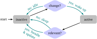
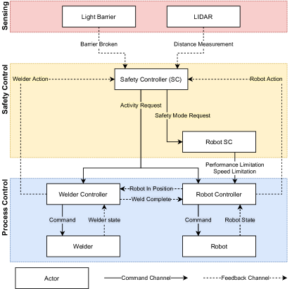
A safety controller is introduced to the \acCDT as a singleton node declared as an abstract actor. communicates on fixed channels with a family of process actors . The nominal procedure of is governed by a local hierarchical state machine responding to process updates on . To allow the safety controller to intervene in this nominal procedure, the interpreter behaviour is implemented as a parent state machine as seen in Figure 17. This secondary state machine allows then a safety controller to enact changes to ’s safety mode(s) in response to requests made over channels in .
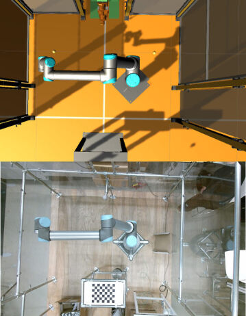
As part of the case study presented in Section 2, an environment has been developed to evaluate the synthesised safety controller. This environment, shown in Figure 16, presents us with a distributed system composed of multiple digital twins, with each physical actor (e.g. robot, spot welder, operator) and component (e.g. sensors) in the real-world process assigned its own individual twin.
The process is a work-piece exchange and welding task, overseen by a process controller that issues and responds to tasks assigned to each actor. The safety controller observes feedback from the process controller, a workbench light barrier and a LIDAR positioned within the cell. Figure 17 then describes the communication of safety mode and activity change requests to all actors within the environment on occurrence of a critical event, following the event handling logic in Figure 15.
6.3 Controller Validation by Testing
The validation of a controller implementation in the \acCDT can be done by use-case-based testing of scenarios generated from the process model . Given a use case , a misuse case , an initial state , a set of traces in vicinity of , we say that , as deployed in the \acCDT, conforms with with respect to , written , if and only if . Moreover, we say that complies with with respect to if and only if . Finally, we say that the controller implementation is -valid if and only if and the closest we can find, with and no overlap with regarding , suggests implausible inputs to the \acCDT.
For controller testing, we translate requirements given as \acPCTL properties (Table 3) into corresponding linear and metric temporal logic properties in . Particularly,
| (6) |
requires to detect the critical event, that is, to get active whenever the sensor predicate holds true within time units. Furthermore,
| (7) |
states for a completed process () that whenever the controller detects (Table 1) it moves the \acCDT to a state where is mitigated () and from there, given the environment (e.g. operator) eventually reacts, it returns the process to a state where is inactive and operation is resumed as far as possible (). Even if the environment does not react, an accident never occurs ().
We describe and as (generated) sequences of inputs to the \acCDT and the vicinity as a set of (randomly generated) configurations of the \acCDT (e.g. considering the operator being far, near, and close to the spot welder, and entering the cell at different times). We statistically explore by playing in a sample to the \acCDT, record the event trace , and verify using the metric temporal logic run-time checker pyMTL [pyMTL2019].
Data Extraction.
To allow communications between actors to be recorded and analysed, an additional abstract actor is introduced as a network snooper. This actor subscribes to updates from a family of actors and exposes their communications externally as a series of discrete event streams. As the scenario is executed, the generated streams are marked with a reference time and origin of each data packet. Communications between the safety controller, process controller and other process members are then recovered for forensic analysis and evaluation of the safety controller.
The safety controller may be exported as a C# extension to our \acCDT and deployed within a digital twin of the case study in Section 2. At the point of analysis, each data stream is composed of a series of data packets with an assigned timestamp and entity identifier. Each event stream from time is exported from the database following the scenario execution. This allows the data to be presented as a ledger of all monitored channels, indicating where inter-actor communication occurred, actor states have changed and instances where the controller guards have been triggered.
7 Evaluation
In this section, we pose three research questions about safety, utility, and scalability, describe the evaluation methodology for each of these questions, and discuss the results of our evaluation.
7.1 Research Questions and Methodology
Based on the questions raised in Section 1, we investigate key aspects of our approach by asking three research questions (RQs).
- RQ1 (Safety)
-
What is the likelihood of accident-free operation under the control of a synthesised safety controller?
- RQ2 (Utility)
-
Does the safety controller reduce the number of hard stops of the robot due to hazards, compared to a basic controller that switches off the system whenever the operator intrudes the work cell?
- RQ3 (Scalability)
-
How well can the proposed approach deal with multiple hazards and mitigation and resumption options?
Methodology for RQ1 (Safety).
We answer RQ1 in two stages, first based on our modelling approach (RQ1a) and, second, supported by our deployment and validation approach (RQ1b).
Methodology for RQ1a.
We evaluate freedom from accidents according to Equation 5, leading to probability triples comprising , the arithmetic , and .
In the \acMDP setting, we use Prism to synthesise policies from according to the three optimisation queries
| (a) | ||||
| (b) | ||||
| (c) |
where . In the spirit of negative testing, Equation a aims at maximising the use of the safety controller (i.e., approximating worst-case behaviour of the operator and other actors) while maximising the probability of finishing two tasks, that is, finishing a workpiece and carrying through cell maintenance. This query does not take into account further opmitisation parameters defined for mitigations and resumptions. As opposed to that, Equation b fosters the maximisation of productivity, any combination of decisions allowing the finalisation of tasks is preferred, hence, transitions leading to accidents or the use of the controller are equally neglected. While Equation c also forces the environment to trigger the controller, these policies represent the best controller usage in terms of nuisance and effort. Because of restrictions in the use of for \acpMDP, we maximise costs interpreting positive values as negative (e.g. the higher the nuisance the better). We then investigate the Pareto front of optimal policies synthesised from the Equations a, b, and c. For policies with less than 1000 states, we inspect the corresponding policy graphs (e.g. whether there is a path from to or whether paths from unsafe states reachable from avoid deadlocks). Finally, we evaluate accident freedom according to Equation 5, except that we use for \acpDTMC instead of .171717To keep manual workload under control, if the model checker (here, Prism) lists several adversaries, we apply the experiment only to the first listed.
In the \acpDTMC setting, we use evoChecker to synthesise policies for according to the objective
| (8) | ||||
| (Productivity) | ||||
| (Nuisance) | ||||
| (Risk) |
over a time period and with factor-specific scaling factors . This objective contains a probabilistic constraint ruling out early deadlocks, and three optimisation queries for maximising productivity, minimising nuisance, and minimising overall risk from a factor set . We then assess the resulting Pareto front, extract a solution from this front, and use Yap to refine that solution into a concrete controller.
Methodology for RQ1b.
In Section 5.2, we described the synthesis of a correct abstract controller and, in Section 6.1, its translation into a concrete controller interfacing with the \acCDT explained in Section 6.2. Then, how do we assure the transfer of the results on freedom from accidents of the abstract controller (RQ1a) to the concrete one in the \acCDT? For this, we follow the framework in Section 6.3 and deploy and test in the \acCDT for compliance with in certain use cases and assess its behaviour in misuse cases.
The \acCDT is used in a simulation capacity to validate the proposed safety controller. The simulation provides for (i) automated testing and (ii) a safe environment for evaluation, whilst representing a faithful one-to-one construction of the work cell. Physical, digital, or mixed environments expose the same interface for integration with the \acCDT; the same controller can be used in either context without modification. As such, integration with the physical work cell is not evaluated, in part due to limited access to the lab replica.181818At the time of writing, COVID-19 prevents access to the Sheffield Robotics lab and physical components of the case study.
We follow one use case () and one misuse case () to exercise the risk factors , , and described in Table 1:
-
:
During operation, the operator reaches across the workbench and walks to the spot welder.
-
:
During operation, an operator reaches across the workbench while another operator walks to the spot welder.
We perform tests for the use case as outlined in Figure 19g. The operator first heads to the workbench, breaking the light barrier (), before heading inside the cell () close to the spot welder (). The observed stream of events during each test can be split for the independent validation of each risk factor. Considering the stream as a whole provides for the validation of hazard mitigation and the absence of impact on further actions.
The operator waits at given positions while the cobot and spot welder proceed through their scheduled activities. Variations in the time spent by the operator in different states result in different interleavings of the operator and robot, and such variations in turn might be ground for the activation of hazards in the system. The configuration for each test is a vector of 4 values corresponding to 4 wait operations of the operator: entering the workbench, at the workbench, entering the work cell, and at the spot welder. To bound the time taken by each test, the values are picked such that the operator completes its actions in less than 20s. This is ample time for the robot to perform its own actions, and the operator is able to disrupt the different tasks in the process either by walking to the spot welder or reaching across the workbench. We rely on the Dirichlet-Rescale algorithm [Griffin2020-DRSSamplingAlgo] for generating vectors such that the values of the vector sum to a given total, and the distribution of vectors in the constrained space is uniform.
We rely on situation-based coverage criteria, proposed by Alexander2015-SituationCoverage, to assess the performance of our test campaign, and whether we have achieved a satisfactory level of testing. We define our situations in terms of either the actions of the spot welder, the actions of the robot, or the position of the arm, when the operator is reaching at the workbench or entering the cell in accordance with the use case. Full coverage is achieved when all such actions or positions have been observed under both interference factors. We also ensure all valid states for all risk factors have been encountered (as defined in Figure 7). This ensures causal factors have been encountered, mitigated, and the system could resume operation.
Methodology for RQ2 (Utility).
We argue that the synthesised safety controller is better than a state-of-the-art controller that only has a stop mode and performs no automatic resumption. For this argument, we compare the whole range of controllers from the design space with those controllers that always perform a safety stop when detecting a critical event. Based on that, we informally assess the increase in productivity and fluency of collaboration, and the decrease of mean-time to finishing a process cycle. This argument underpins our contribution to the problem statement in Section 1.
Methodology for RQ3 (Scalability).
We prepare and analyse multiple increments of the risk model, each adding one critical event, mitigation options, and constraints to the model. We record the resulting model sizes and analysis times.
7.2 Results
In the following, we present the results of our evaluation separately for each research question.
7.2.1 Results for RQ1a: Safety in the Model
We consider as inputs a risk model and a process model of the work cell, with a single initial state of these models where all actors are in the activity off and no critical event has occurred. The risk model is given in Yap’s input language and the behavioural model is given in Prism’s flavour of \acpGCL, instrumented with Yap template placeholders. We consider the two settings explained in Section 5. In the \acMDP setting, we use Yap 0.5.1 for generating the design space (Section 5.1) embedded into a process model without alternating execution semantics and with controller synthesis directly from an \acMDP using Prism 4.5. In the improved \acpDTMC setting, we use Yap 0.7.1 for generating the design space embedded into a process model with the alternating execution semantics described in Section 4.1.1, an improved accident model, and with controller synthesis from a \acpDTMC using evoChecker and Prism 4.5. For RQ1a, we used GNU/Linux 5.4.19 and 5.8.0 (x86, 64bit), and an Intel® Core i7-8665U CPU with up to 8 Threads of up to 4.8 GHz, and 16 GiB RAM.
| Risk Model† | \acMDP† | (a) max-ASC† | (b) max-prod | (c) opt-ASC | |||||||||||
| [ms] | [s] | [s] | [s] | ||||||||||||
| 5/0 | 3 | 40 | [.9,.9,.9] | 14 | 322/1031 | [1,1,1] | 3 | .02 | [1,1,1] | 1 | .02 | [1,1,1] | 6 | .15 | |
| 9/2 | 5 | 52 | [.92,.96,.98] | 256 | 930/3483 | [.07,.66,1] | 11 | .77 | [0,.88,1] | 8 | .82 | [.95,.98,1] | 18 | .9 | |
| 11/3 | 8 | 44 | [.93,.97,1] | 288 | 1088/3865 | [0,.29,1] | 17 | 2.1 | [0,.8,1] | 5 | 2 | [1,1,1] | 24 | 1.5 | |
| 13/7 | 16 | 65 | [.93,.97,1] | 981 | 7675/33322 | [1,1,1] | 17 | 9.7 | [1,1,1] | 11 | 9.4 | [1,1,1] | 15 | 13.3 | |
| 15/8 | 36 | 76 | [.93,.97,1] | 2296 | 21281/98694 | [1,1,1] | 15 | 42.9 | [0,.71,1] | 7 | 41.4 | [1,1,1] | 15 | 46.6 | |
| 15/9 | 50 | 87 | [.93,.97,1] | 2864 | 21965/100133 | [1,1,1] | 13 | 48.2 | [1,1,1] | 9 | 46.4 | [1,1,1] | 15 | 53.8 | |
| 15/15 | 122 | 162 | [.93,.99,1] | 12079 | 21670/102263 | [0,.94,1] | 35 | 38 | [0,.72,1] | 22 | 36.6 | [1,1,1] | 36 | 51.1 | |
| † …critical event set; mr/c…number of mitigations+resumptions/constraints; …cardinality of the relevant subset of defined in Section 3.3; …Yap’s processing time; …probability of conditional freedom from accidents; …set of -unsafe states; …number of states/transitions of the \acMDP ( equals the size of the policies); Equations a, b, and c…optimisation queries; …Prism’s processing time | |||||||||||||||
The results for the original \acMDP setting are displayed in Table 4, which shows the data collected based on seven increasingly more complex risk models. The probability triples are denoted by . The result for a policy denotes 100% conditional freedom from accidents. This desirable result is most often achieved with Equation c due to the fact that simultaneity of decisions of the environment and the safety controller in the same state is avoided by focusing on rewards only specified for controller actions. Such rewards model the fact that a controller is usually much faster than an operator. Equations a and b show poorer freedom from accidents because productivity rewards given to the environment compete with rewards given to the safety controller to exploit its risk reduction potential.
| Process … | |||
|---|---|---|---|
| …with a safety controller | 63% | 97% | 100% |
| …without a safety controller | 63% | 87% | 100% |
In the improved \acpDTMC setting, we focus on a single risk model with the three factors , , and . We calculate for Equation 5 for a process without a safety controller and one with a controller. Table 5 shows an increase in average freedom from accidents from 87% to around 97% when using a safety controller. Starting from any state in the process shows that there are very safe states with a probability of accidents of down to 0% ( column) and rather dangerous states with a probability of up to 37% ( column). Overall, going from 13% down 3% average accident probability (across the three risk factors) means that the controller in this particular process leads to a reduction of accidents by 77%.
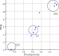
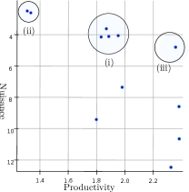
The 3D Pareto front in Figure 18 indicates that the lower the risk of a controller (Conjunct Risk in Formula 8) the lower the productivity (Conjunct Productivity) due to the interventions of the controller (cf. Figure 18a). Figures 18a and 18b show (i) four controllers in the design space with low nuisance (Conjunct Nuisance) and medium productivity and risk, and (ii) two minimal-risk controllers with low nuisance but low productivity. (iii) Controllers that minimise nuisance and maximise productivity tend to do this at the cost of high risk. If the minimal-risk controllers under (ii) are not satisfactory, a more detailed trade-off regarding the controllers in (i) or a repetition of the analysis with different design parameters or an altered process and controller model will have to be made.
7.2.2 Results for RQ1b: Safety in the Digital Twin
We performed 100 tests for the use case shown in Figure 19g. This proved sufficient to achieve full coverage of (i) the mitigation states for all considered risk factors, and (ii) operator interference types across spot welder and cobot states. All recorded traces verify , that is, all traces satisfy the selected properties translated from Table 3. Risk factors were correctly detected (with in Property 6) and mitigated by the synthesised safety controller in all observed situations in the \acCDT. All results for RQ1b were produced under the Windows 10 Home Edition operating system, build 19042.985, on an Intel® Core i5-8250U 4-core CPU at 1.8 GHz, with 8 GiB RAM. The whole test suite, including validation of the traces, took less than two hours to complete. No time compression was used, the \acCDT ran simulations in real-time.
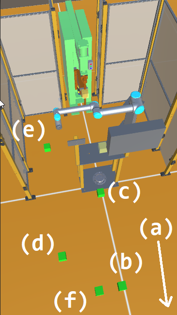
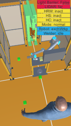
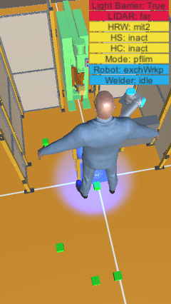
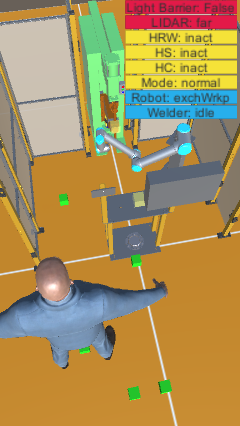
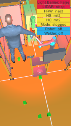
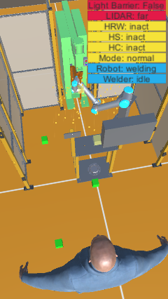
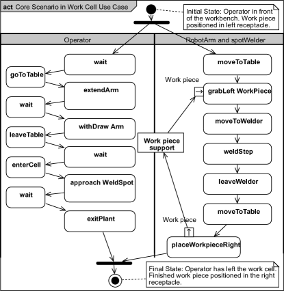
Figure 19 illustrates the output of the \acCDT for the use case (Figure 19g). Each image captures the state of the system as the operator begins a wait operation. The use case highlights the activation of all monitored risk factors (see Table 1) with the operator and cobot making concurrent use of the workbench, and the operator in the vicinity of the spot welder as an operation is about to start.
relies on two operators simultaneously following the behaviours outlined by . The tested model assumes a single operator interacts with the system, such that an operator must leave the workbench before entering the work cell. As such, the safety controller correctly mitigates the risk due to both cobot and operator reaching for the workbench. However, as the second operator enters the cell the related risk factors are neither identified as active nor mitigated. Figure 20 highlights the situation, with the second operator in close proximity to an active spot welder.
The work cell is safe considering a single operator following the use case, that is entering the work cell or the workbench during operation. However, the risk and process models would need to be revised to account for multiple operators interacting with the system (e.g. by removing factor dependencies between and , see Section 4.2.1). The case with two operators would normally be picked up in an extended risk assessment following Table 1, but it was not relevant to this particular process. This case is also not within scope for the purposes of keeping this example simpler.
7.2.3 Results for RQ2: Utility
In the \acMDP approach, Table 6 highlights several aspects. First, the fact that none of the controller configurations achieves the productivity level (64.19) of the process without a controller. Such a process reaches a theoretical productivity maximum assuming no safety requirements, which is for obvious reasons not desirable. Perhaps unsurprisingly, safety comes at the cost of productivity. However, more importantly, among all configurations, the one switching to “stopped”, whenever , , or occurs, is the one performing the poorest (37.06, highlighted in gray). As expected, controllers implementing the pflim and ssmon safety modes as part of their policy are among the highest performing variants (51.42). With the best safety controller, the process achieves about 40% more productivity than with the worst controller and is only 25% less productive than the maximum productivity achievable in the process.
Moreover, the most risky configurations (68, highlighted in gray) are around 77% less risky than not using a safety controller. However, the most difficult trade-off is to be made between very low risk controllers () and moderate risk controllers () where the gain in productivity is comparatively little. Finally, with this model instance, the addition of the factor does neither influence risk nor productivity.
Regarding the expected overhead (Section 6.1), we used the C# profiling tool integrated in the development environment for the \acCDT. We measured the execution time of control cycles in the \acCDT across 1000 invocations of the controller. Our observations cover both nominal activity, and the occurrence of risk factors. The longest observed execution time , its high watermark, is around . The high watermark occurs upon activation of a risk factor, and accounts for mode switch, and the required mitigation actions. In the absence of a mitigation requirement, the average execution time is less than . Execution times are expected to be lower in the physical twin. Profiling was performed on the same environment as for RQ1b, that is a 1.8 GHz i5 CPU with 8 GiB of RAM running Windows 10.
7.2.4 Results for RQ3: Scalability
We answer this question using six increments applied to a basic risk model (Table 4). We only consider the \acMDP setting because applying model increments in the \acpDTMC setting will not provide additional insights into the scalability aspect of our method.
For demonstration of Yap’s capabilities, the incident and the accident are included in the risk model without handler commands. However, these factors add further constraints on to be dealt with by the safety controller. Hence, stays at 15 actions and rises to constraints. In model 7 (last line of Table 4), (122 risk states) and the -region of (12079 states) differ by two orders of magnitude. Risk states offer a higher level of abstraction for risk assessment. The derivation of properties that focus on relevant regions of the \acMDP state space from a risk structure can ease the state explosion problem in explicit model checking. For example, the constraints prevents and prevents express that the combined occurrence of and is considered infeasible or irrelevant by the safety engineer. Hence, checking properties of the corresponding region of the \acMDP state space can be abandoned.
7.3 Threats to Validity
Internal Validity.
Too strong environmental assumptions reduce the scope of the safety guarantee. To limit the need for game\Hyphdashtheoretic reasoning about , we reduce non\Hyphdashdeterministic choice for the environment (i.e., operator, cobot, spot welder). The more deterministic such choice, the closer is the gap between the policy space and the controller design space. Any decisions left to the environment will make a verified policy safe relative to ’s environmental decisions. These decisions form the assumption of the controller’s safety guarantee.
| Process | Configuration† | Productivity‡ | Risk‡ | ||
| [units] | [units] | ||||
| smrst / idle | stop | stop | 37.06 | 0 | |
| stop / off | stop | stop | 37.06 | 0 | |
| hguid / – | stop | stop | 37.06 | 0 | |
| smrst / idle | pflim | stop | 44.75 | 9 | |
| stop / off | pflim | stop | 44.75 | 9 | |
| hguid / – | pflim | stop | 44.75 | 9 | |
| smrst / idle | stop | pflim | 46.26 | 49 | |
| stop / off | stop | pflim | 46.26 | 49 | |
| Using controller | hguid / – | stop | pflim | 46.26 | 49 |
| smrst / idle | stop | ssmon | 48.15 | 59 | |
| stop / off | stop | ssmon | 48.15 | 59 | |
| hguid / – | stop | ssmon | 48.15 | 59 | |
| smrst / idle | pflim | pflim | 49.90 | 58 | |
| stop / off | pflim | pflim | 49.90 | 58 | |
| hguid / – | pflim | pflim | 49.90 | 58 | |
| smrst / idle | pflim | ssmon | 51.42 | 68 | |
| stop / off | pflim | ssmon | 51.42 | 68 | |
| hguid / – | pflim | ssmon | 51.42 | 68 | |
| No controller | – | – | – | 64.19 | 291 |
|
†Configuration of mitigation options (safety mode and
activity switches),
smrst: safety-rated monitored stop,
stop: power shutdown with user-initiated work cell reset,
hguid: hand-guided operation,
pflim: power & force limitation,
ssmon: speed & separation monitoring,
idle: currently not performing work steps,
off: work cell not in operation.
‡According to and Property (Risk) with . |
|||||
Occupational health and safety assumes trained operators not to act maliciously, suggesting “friendly environments” with realistic human errors. To increase the priority of the controller in the MDP-based approach, we express realistic worst-case assumptions, for example, by minimising factor- and activity-based risk and maximising the risk reduction potential. The \acpDTMC-based approach weakens such assumptions by the fact that all outcomes of environmental decisions remain in the policy in form of probabilistic choices. Hence, the controller extracted from will contain an optimal choice for all states reachable from environmental decisions. Obtaining appropriate trade-offs between productivity and safety is challenging. Hence, in the future we may switch to game-theoretic approaches which may allow for a more nuanced view of the environment and hence allow for even greater productivity.
Incorrect application of tools. evoChecker relaxes constraints if the constrained solution space is empty, leading to solution under relaxed constraints. Hence, the design space needs to be redefined in order for evoChecker to select from a non-empty set of solutions obeying safety-related hard constraints.
Insufficient validation. Confidence in the testing-based validation depends on the range and complexity of (mis)use cases and the parameters used for randomisation. The use case for RQ1b is generic enough to cover a wide range of work cell scenarios and the misuse case clarifies the environmental assumptions of the use case.
External Validity.
Reality gap through inadequate quantification. The lab replica of the work cell matches closely to the one in the company. This allowed us to develop an accurate digital twin and an \acMDP compliant with the actual work cell that incorporates all relevant parameters (particularly, probabilities). We crafted the \acMDP such that assessment and optimisation based on probabilities and rewards rely more on qualitative relations between the parameters rather than accurate numbers. It is more important and easier to conservatively assess whether an activity or safety mode is more or less dangerous than another and it is less important and more difficult to provide accurate numbers. The resulting gap between optimality in the model and optimality in the digital twin should hence not alter the demonstrated confidence in the controller. More accurate numbers can be obtained from observations, and after a model update, a repeated synthesis can improve productivity of the safety controller.
Incorrect sensing assumptions. In our case study, the safety controller relies on the detection of an operator (e.g. extremities, body) and a robot (e.g. arm, effector) entering a location, the cell state (e.g. grabber occupied, workbench support filled), and the work piece location (e.g. in grabber, in support). For , we assume the tracking system (i.e., range finder and light barrier in the industrial setting, MS Kinect191919See https://en.wikipedia.org/wiki/Kinect. in the lab replica) to map the location of the operator and robot to the areas “in front of the workbench”, “on the workbench”, “in the workcell”, and “close to the spot welder” rather than to a fine-grained occupancy grid. In Figure 2b, the range finder signals “at welding spot” if the closest detected object is nearer than the close range, and “in cell” if the closest object is nearer than the wide range. Tracking extensions, not discussed here, could include object silhouettes and minimum distances, operator intent, or joint velocities and forces.
Incorrect real-time behaviour. \acpGCL, as we used it, requires care with the modelling of real-time behaviour, particularly, when actions from several concurrent modules are enabled. To model real-time controller behaviour, we synchronise operator actions with sensor events and, in the original \acMDP setting, force the priority of controller reactions in by maximising the risk reduction potential (cf. in Table 3). While synchronisation restricts global variable use, increasing ’s state space, we found it to be the best solution in the multi-module \acMDP setting. The alternating execution scheme used in \acpDTMC setting, however, avoids the use of rewards to implement priorities and prevent actors from competing in an unnatural way.
7.4 Discussion
Tool Restrictions and Model Debugging.
State rewards allow a natural modelling of, e.g. risk exposure. However, in Prism 4.5, one needs to use action rewards for multi-objective queries of \acpMDP. Risk gradients help to overcome a minor restriction in Prism’s definition of action rewards.202020Currently, rewards cannot be associated with particular updates, that is, with incoming transitions rather than only states. Alternatively, we could have introduced extra states at the cost of increasing ’s state space, undesirable for synthesis. Rewards require the elimination of non-zero end components (i.e., deadlocks or components with cycles that allow infinite paths and, hence, infinite reward accumulation). Prism provides useful facilities to identify such components, however, their elimination is non-trivial and laborious in larger models and can require intricate model revisions. We strongly discretise model parameters such as location to further reduce the state space and keep the model small. We use probabilistic choice in synchronous updates only in one of the participating commands to simplify debugging. We avoid global variables to support synchronisation with complex updates
Misuse Cases for Controller Testing.
Misuse cases help in exploiting deficiencies of a control concept through counterexamples. The latter can be generated from the process model and exercised as negative test cases to aid in debugging the controller. We explored this idea in Gleirscher2011-HazardbasedSelection, applying a Prolog-based Golog interpreter that constructs counterexamples from backward depth- and breadth-first search from a given accident state. Prism uses forward breadth-first search from an initial state and stops when reaching an accident state. In both cases, explicit state exploration is used with the usual problem of state space explosion. In any case, an environment model is needed to express accident states. In this work, we prefer a model checker because the encoding of the stochastic process in \acpGCL appeared to be easier than in a stochastic situation calculus and because of more flexibility of expressing properties to be verified in \acPCTL.
8 Related Work
Our work builds upon a set of well known theoretic principles on which research on controller design and synthesis [kress-gazit_synthesis_2018] for collaborative robots has been carried out. In the following, we compare our results with other results.
Risk-informed Controller Design and Verification.
Askarpour2016-SAFERHRCSafety discuss controller assurance of a cobot work cell based on a discrete-event formalisation in the linear-time temporal language TRIO. Actions are specified as pre/inv/post-triples for contract-based reasoning with the SAT solver Zot. Violations of the safety invariant inv lead to pausing the cell. Fine-grained severity quantification [vicentini_safety_2020] allows a controller to trigger safety measures on exceeding of certain risk thresholds. Additionally, askarpour_formal_2019 present a model of erroneous or non\Hyphdashdeterministic operator behaviour to enable designers to refine controller models until erroneous behaviours are mitigated. This approach aims at risk-informed prototyping and exhaustive exploitation of all possible executions to identify constraint violations and remove hazardous situations. Risk thresholds correspond to a refined variant of Property (6). Whilst not the focus of this work, our approach also allows for the quantification of severity in detector predicates (). Their severity model [askarpour_formal_2019, vicentini_safety_2020] inspires future risk factor models. Instead of a priority parameter, which reduces state variables, we use guards to implement action orderings. Our approach is more flexible because it can deal with multiple mitigation options offering more variety in safety responses. Beyond model consistency checks and the search of counterexamples for model repair, our approach yields an executable policy. Our use of \acpGCL and \acPCTL [Kwiatkowska2007-StochasticModelChecking] results in a separation of action modelling and property specification. Although this separation is a non-essential difference, it syntactically supports a more independent working on two typical abstraction levels, required process properties and process implementation.
Verified Controller Synthesis for Cobots.
A number of authors have suggested synthesis approaches for controllers in human-robot collaboration. Key features of these approaches are verified optimal synthesis for collaborative plan execution, quantitative verification of plans, code generation for deployment on robot platforms.
For generic robots, Orlandini2013-ControllerSynthesisSafety and bersani_pursue_2020 employ synthesis by game solving (i.e., finding winning strategies) over timed game automata (TIGA) supported by the model checker UPPAAL-TIGA. Correctness properties can be formulated as reach-avoid problems (i.e., reach the goal state and avoid unsafe states) specified as in timed computation tree logic. From a timeline-based plan description [Cesta2008-timelinerepresentationframework], Orlandini2013-ControllerSynthesisSafety generate a TIGA with clock constraints encoding temporal degrees of freedom for performing control actions. From the TIGA, a winning strategy (i.e., a robust plan execution minimising violations of clock constraints) is then synthesised. The TIGA-based stage is continuously performed during operation. The distinction of controllable (i.e., duration known) from uncontrollable actions (i.e., duration unknown) allows one to react to temporally uncertain environmental events by obtaining strategies that can schedule robot actions in the presence of worst-case timing of the environment. In Cesta2016-Towardsplanningbased, an extension of this approach is applied to controller synthesis for safe human-robot collaboration. For task coordination between humans and robots, Cesta2016-Towardsplanningbased and other works utilise the distinction of uncontrollable and controllable actions. Our reactive execution scheme (Figure 5) accommodates this basic feature required to separate the capabilities of the cobot from the capabilities of its physical environment.
kshirsagar_specifying_2019 demonstrate on-line controller synthesis for human-robot handovers obeying timing constraints specified in signal temporal logic. Cobot kinetics need to be given in terms of ordinary differential equations. Being suitable for low-level synthesis in homogeneous action systems, this approach could be integrated into our framework, for example, for controlling a speed and separation monitoring mode switched on during a handover.
MDP policy synthesis has also been used to generate optimal motion plans for mobile robots [lahijanian_temporal_2012]. The \acpMDP used in this solution model the physical layout of the space within which a mobile robot can navigate. As such, the problem addressed in this work is complementary to our use of probabilistic models and \acMDP policy synthesis, as our approach tackles the generation of optimal hazard mitigation actions.
Modelling of Controllers for Cobots.
Domain\Hyphdashspecific languages for controller design can support control engineers in encoding their control schemes. Cesta2016-Towardsplanningbased employ domain and problem definition languages (DDL & PDL) for encoding the state spaces and action domains a controller can select from. bersani_pursue_2020 provide a lean language for robotic controller design. Models in that language typically include a description of the uncontrollable environment. Safety properties can be difficult to formulate, as shown in bersani_pursue_2020 and, particularly, when dealing with multiple hazards or risk factors. We provide Yap’s input language for safety controller design informed by risk models, streamlining the specification of safety properties from multiple hazards.
Approaches such as lahijanian_temporal_2012 and kshirsagar_specifying_2019 focus on homogeneous action systems, that is, systems with few and similar types of actions manipulating type-wise simple state spaces (e.g. movement in a Euclidean plane or in a 2D grid). Such systems make it easier to provide complete and tractable synthesis algorithms for realistic models. In contrast, and as suggested by kress-gazit_synthesis_2018, our approach focuses on heterogeneous action systems, such as human-robot collaboration, which can be characterised by a wide variety of actions over a heterogeneously typed state space. Such actions can differ in their complexity and discrete or continuous nature (e.g. grabbing a work piece, moving a robot arm, performing a welding action, switching a mode, turning off an alarm sound).
Robust controllers are able to deal with unstructured environments, to react to a wide variety of uncontrollable adverse events (e.g. human error). Overall, they guarantee correct behaviour under weak assumptions. Game-based approaches, such as policy synthesis for TIGAs [raskin_guided_2007, Orlandini2013-ControllerSynthesisSafety, bersani_pursue_2020], inherently support such environments. Whilst our \acMDP-based approach benefits from more efficient algorithms and provides fine-grained methodological guidance, an extension to utilise the greater flexibility of game-based approaches should be part of our next steps.
A distinctive feature of safety controllers is their ability to control the resumption of normal operation (i.e., the recovery from a conservative or degraded safe state) in addition to mitigation. While resumption is implicit to many solutions for homogeneous\Hyphdashaction reach\Hyphdashavoid problems [Orlandini2013-ControllerSynthesisSafety, bersani_pursue_2020], for heterogeneous action systems, resumptions often need to be modelled separately (e.g. switching off a safety mode or function, resuming/restarting a suspended/cancelled task). Risk factors at the core of our approach accommodate primitives for specifying resumptions.
Overall, an advantage of timeline-based approaches [Cesta2016-Towardsplanningbased] is their ability to encode physical domains qualitatively. In \acpGCL, corresponding domain constraints need to be distributed over action guards, which can be cumbersome. Moreover, an advantage of TIGAs over \acpMDP is that time is continuous and managed via clocks, leading to more concise models. However, in summary, our use of \acpGCL enables the concise encoding of the action domain of human-robot collaboration with multiple actors operating over a discrete state space. \acpMDP represent a natural model of interaction of agents with an uncontrollable and uncertain environment. Reward-enhanced \acPCTL provides a flexible and expressive language for specifying multiple objectives (e.g. minimum risk, maximum performance) and reward constraints (e.g. accepted risk thresholds). We could enhance our approach to probabilistic timed automata in order to further increase model fidelity.
Controller Deployment.
An important step in many synthesis approaches is the deployment of the resulting controllers in an execution environment. Although for another domain (i.e., climate control in a pig stable), raskin_guided_2007 show how controllers synthesised using UPPAAL-TIGA can be embedded as components of a Simulink model to perform validation by simulation. As part of their evaluation, bersani_pursue_2020 demonstrate the deployment of their controllers on the low-cost platform Turtlebot used as a cobot. Orlandini2013-ControllerSynthesisSafety deploy their approach as a module on a GM-based robotic software platform with a mapping into the real-time framework BIP. Their flexible approach could be a potential route for future extensions of our approach. Currently, Yap provides a generator for C# modules for the \acCDT (Sections 3.4 and 6.2).
Overall, to the best of our knowledge, our method is the first end-to-end approach to synthesising and deploying safety controllers for handling multiple risks from collaborative robots in manufacturing processes. The works discussed above either address parts of the synthesis challenge or implement alternative solutions for cobot (safety) controllers.
9 Conclusion
We introduced a tool-supported software engineering approach for the verified synthesis of optimal safety controllers from \aclpMDP, focusing on human-robot collaboration. These software controllers implement regulatory safety goals for such applications. We describe steps for streamlined application modelling and risk-informed controller design and demonstrate our method using a tool chain consisting of Yap [Gleirscher-YapManual] for structured risk modelling and \acpGCL program generation, evoChecker [Gerasimou2018-Synthesisprobabilisticmodels] for search-based policy synthesis from \acppDTMC, and Prism [Kwiatkowska2011-PRISM4Verification] for probabilistic model checking and \acMDP policy synthesis. We show that our approach can be used to incrementally build up multi-hazard models including alternative mitigation and resumption strategies. We also discuss how our approach can simplify explicit model checking when dealing with large state spaces. Our approach improves the state of the art of controller synthesis for collaborative robots, particularly when dealing with multiple risks, mitigation options, activities and safety modes. That way, we contribute to the alignment of lower-level requirements posed by cobot safety standards (e.g. ISO 15066) with higher-level cobot hazard analysis and risk assessment [Chemweno2020-Orientingsafetyassurance] through a structured risk-informed design approach. Furthermore, we translate the verified controllers into executable code and deploy them on the \aclCDT and, thus, accomplish a smooth transition between formal controller verification and testing-based controller validation in a realistic environment. Using the \acCDT, we demonstrate the controller’s correct and timely response in a representative use case. In summary, the verification and validation results generated by our approach can contribute evidence to a controller assurance case [Gleirscher2019-EvolutionFormalModel, Foster2020-TowardsDeductiveVerification, entrust2018].
Future Work.
For optimal synthesis, the proposed method uses parameters such as upper risk and severity bounds as constraints. We plan to introduce parameters for probabilities, such as sensor failure and human error, into the \acMDP and to use parametric risk gradients by extending Yap.
It is important to model all relevant behaviours of the environment, or more generally the uncontrollable actions, the safety controller needs to respond to in order to increase freedom from accidents. Hence, in future work, we plan to use stochastic games to more accurately (and less conservatively) model the behaviour of the environment in which this controller operates. We also plan to explore online policy synthesis [synthesis2017] to allow more variety in environmental decisions (e.g. mitigating hazards due to malicious operators). This corresponds to weakening the assumptions under which the controller can guarantee safety.
Accident data for the considered industrial application was generally not available. We were also unable212121Due to restricted lab access during the COVID-19 pandemic. to collect data from the lab replica. Thus, we had to make best guesses of probabilities (cf. Section 4.3). However, the frequency of undesired intrusion of operators into the safeguarded area and accident likelihood can be transferred into our case study.
The \acCDT is a full-fledged digital twin, from which the interaction between the safety controller and the real system can be demonstrated. Limited access to the physical cell has required validation in the digital twin to take precedence. Further validation integrating the physical work cell will therefore be the focus of future work.
The case study can be extended by randomised control decisions with fixed probabilities (e.g. workload), by adding uncertain action outcomes (e.g. welding errors), and by time-dependent randomised choice of mitigation options. To use time in guarded commands, we want to explore clock-based models rather than only using reward structures, as far as the synthesis capabilities allow this.
For motion planning over finite partitions of geometric spaces, lahijanian_temporal_2012 describe algorithms for the synthesis of \acMDP policies that maximise the probability of a given arbitrary \acPCTL formula. By assuming that state estimation is precise, the authors avoid the use of partially observable \acpMDP in their application. To improve our approach regarding the synthesis over homogeneous action systems, their algorithms could be integrated into our \acMDP synthesis tool chain, for example, in addition to Prism or underpinning the search-based synthesis in evoChecker.