Dynamics and Nonmonotonic Drag for Individually Driven Skyrmions
Abstract
We examine the motion of an individual skyrmion driven through an assembly of other skyrmions by a constant or increasing force in the absence of quenched disorder. The skyrmion behavior is determined by the ratio of the damping and Magnus terms, as expressed in terms of the intrinsic skyrmion Hall angle. For a fixed driving force in the damping dominated regime, the effective viscosity decreases monotonically with increasing skyrmion density, similar to what is observed in overdamped systems where it becomes difficult for the driven particle to traverse the surrounding medium at high densities. In contrast, in the Magnus dominated regime the velocity dependence on the density is nonmonotonic, and there is a regime in which the skyrmion moves faster with increasing density, as well as a pronounced speed-up effect in which a skyrmion traveling through a dense medium moves more rapidly than it would at low densities or in the single particle limit. At higher densities, the effective damping increases and the velocity decreases. The velocity-force curves in the Magnus-dominated regime show marked differences from those in the damping-dominated regimes. Under an increasing drive we find that there is a threshold force for skyrmion motion which increases with density. Additionally, the skyrmion Hall angle is drive dependent, starting near zero at the threshold for motion and increasing with increasing drive before reaching a saturation value, similar to the behavior found for skyrmions driven over quenched disorder. We map dynamic phase diagrams showing the threshold for motion, nonlinear flow, speed-up, and saturation regimes. We also find that in some cases, increasing the density can reduce the skyrmion Hall angle while producing a velocity boost, which could be valuable for applications.
I Introduction
Skyrmions are particle-like magnetic textures Mühlbauer et al. (2009); Yu et al. (2010); Nagaosa and Tokura (2013); Everschor-Sitte et al. (2018); Reichhardt et al. (2021) that have been identified in a growing number of materials, including numerous systems in which they are stable at room temperature Woo et al. (2016); Soumyanarayanan et al. (2017); Montoya et al. (2018). Skyrmions can be set into motion with applied currents Nagaosa and Tokura (2013); Everschor-Sitte et al. (2018); Woo et al. (2016); Montoya et al. (2018); Jonietz et al. (2010); Yu et al. (2012); Iwasaki et al. (2013), magnetic field gradients Zhang et al. (2018), and thermal gradients Mochizuki et al. (2014). Due to their size scale, room temperature stability, and mobility, skyrmions are promising candidates for various applications including memory Fert et al. (2013); Tomasello et al. (2014); Fert et al. (2017) and novel computing architectures Zázvorka et al. (2019); Zhang et al. (2020); Pinna et al. (2020). In terms of basic science, skyrmions represent a new class of systems that exhibit collective dynamics under an applied drive Fisher (1998); Reichhardt and Reichhardt (2017), similar to vortices in superconductors Bhattacharya and Higgins (1993); Blatter et al. (1994), colloids Tierno (2012), Wigner crystals Reichhardt et al. (2001) frictional systems Vanossi et al. (2013), and other soft matter systems O’Hern et al. (2003). A unique feature which distinguishes skyrmions from these other systems is the strong gyroscopic or Magnus force component of their dynamics, which generates velocities perpendicular to the net force experienced by the skyrmion Nagaosa and Tokura (2013); Everschor-Sitte et al. (2018); Jonietz et al. (2010); Iwasaki et al. (2013); Everschor-Sitte and Sitte (2014). One consequence of this is that a skyrmion moves at an angle, known as the skyrmion Hall angle, with respect to an applied driving force Nagaosa and Tokura (2013); Everschor-Sitte and Sitte (2014); Reichhardt et al. (2015a, b); Jiang et al. (2017); Litzius et al. (2017). The Magnus term also produces many other effects, including accelerations or speed-ups of skyrmions interacting with barriers or walls Iwasaki et al. (2014); Zhang et al. (2015); Reichhardt and Reichhardt (2016a); Castell-Queralt et al. (2019); Xing et al. (2020), ratchet effects Reichhardt et al. (2015c); Ma et al. (2017); Chen et al. (2020); Göbel and Mertig (2021), and spiraling motion in a confined potential Reichhardt et al. (2021); Büttner et al. (2015); Fernandes et al. (2020) or after a quench Brown et al. (2018). Such effects can be strongly modified by pinning or skyrmion-skyrmion interactions Reichhardt et al. (2021).
Beyond moving skyrmions with currents, other methods that can be used to manipulate individual skyrmions include scanning tunneling microscope tips Hanneken et al. (2016), local magnetic fields Wang et al. (2017); Casiraghi et al. (2019), and optical traps Wang et al. (2020). Extensive experimental and theoretical studies have been performed in systems such as colloids Hastings et al. (2003); Habdas et al. (2004); Squires and Brady (2005); Gazuz et al. (2009); Winter et al. (2012), granular matter Drocco et al. (2005); Candelier and Dauchot (2010); Olson Reichhardt and Reichhardt (2010); Kolb et al. (2013); Reichhardt and Reichhardt (2019a), active matter Reichhardt and Reichhardt (2015), superconducting vortices Straver et al. (2008); Reichhardt (2009); Auslaender et al. (2009); Veshchunov et al. (2016); Kremen et al. (2016); Crassous et al. (2011), various soft matter systems Olson Reichhardt and Reichhardt (2008); Wulfert et al. (2017); Zia (2018); Wang et al. (2019), and metallic glasses Yu et al. (2020) examining the dynamics of individually driven particles moving through an assembly of other particles under either a constant force or an increasing force. Measurements of the velocity-force relations or the drag on the driven particle provide information about how the effective viscosity of the system changes across density-induced transitions such as solid to liquid Reichhardt and Reichhardt (2004); Dullens and Bechinger (2011), liquid to glass Habdas et al. (2004); Gazuz et al. (2009), or unjammed to jammed Drocco et al. (2005); Candelier and Dauchot (2010); Reichhardt and Reichhardt (2019a). For example, the viscosity can increase strongly at the onset of a glass or solid phase produced by an increase in the density. When the probe particle is driven with an increasing force, there can be a force threshold below which the particle is unable to move Hastings et al. (2003); Habdas et al. (2004); Şenbil et al. (2019); Gruber et al. (2020), as well as distinct features in the velocity-force curves Benichou et al. (2013); Illien et al. (2018) which change as the density increases.
In soft matter systems, driving a single probe particle through a background of other particles is known as active rheology Gazuz et al. (2009); Reichhardt and Reichhardt (2019a, 2015); Zia (2018); Gruber et al. (2020). Similar probes have been applied in type-II superconductors using individually dragged vortices Straver et al. (2008); Reichhardt (2009); Auslaender et al. (2009); Veshchunov et al. (2016); Kremen et al. (2016); Crassous et al. (2011). Existing work on active rheology has involved overdamped systems, where the viscosity generally increases with increasing density. It is not clear how the addition of a Magnus term would impact active rheology. For example, it could change the threshold force for motion, increase or decrease the drag, modify the Hall angle, or alter the way in which the probe particle moves with respect to the background particles. Beyond skyrmions, there are many other chiral systems in which Magnus or gyroscopic effects can be important for active rheology, including chiral soft matter fluids and solids, active chiral systems Kokot et al. (2017); Banerjee et al. (2017); Soni et al. (2019); Scholz et al. (2021); Reichhardt and Reichhardt (2020), charged particles in a magnetic field Schecter et al. (1999); Schirmacher et al. (2015), magnetic colloids in oscillating fields Tierno et al. (2007), spinning particles in fluids Grzybowski et al. (2001); Denisov et al. (2018), fluid vortices Ryzhov and Koshel (2013); Aref (2007), and fracton systems Doshi and Gromov (2021).
In this work we study active rheology for skyrmion systems in the absence of quenched disorder using a particle-based model. We apply an external driving force to one skyrmion and measure the velocity components and drag both parallel and perpendicular to the driving direction. For a constant drive, the velocity decreases monotonically with increasing skyrmion density in the damping-dominated regime. This is similar to what has been found for the active rheology of overdamped systems, where it becomes more difficult for the particle to pass through a denser medium due to the increased interactions with other particles. When the Magnus force is dominant, the driven skyrmion velocity has a strongly non-monotonic density dependence and increases with increased density. In this regime, the velocity can be boosted or accelerated beyond the expected velocity for an isolated driven skyrmion in the absence of surrounding skyrmions. As the density increases, the skyrmion Hall angle decreases and the velocity reaches a peak value before decreasing at higher densities. The velocity boost effect arises due to the creation of a locally asymmetric density profile around the driven skyrmion oriented perpendicular to the driving direction. This creates an additional repulsive force on the driven skyrmion which does not cancel out due to the lack of symmetry and is converted by the Magnus term into a velocity component aligned with the driving direction. The behavior is similar to the acceleration effect found for skyrmions interacting with walls and barriers Iwasaki et al. (2014); Zhang et al. (2015); Reichhardt and Reichhardt (2016a); Castell-Queralt et al. (2019); Xing et al. (2020).
For the case of a driving force that is increased from zero, the driven skyrmion exhibits a critical threshold for the onset of motion. The skyrmion Hall angle is zero at the threshold and increases with increasing velocity until it saturates to a constant value at high drives, similar to the behavior found for skyrmions driven over quenched disorder Reichhardt et al. (2021, 2015b); Jiang et al. (2017); Litzius et al. (2017); Reichhardt and Reichhardt (2016b); Legrand et al. (2017); Díaz et al. (2017); Juge et al. (2019); Zeissler et al. (2020); Litzius et al. (2020). In the Magnus dominated regime, the boost effect is nonmonotonic, with reduced boost at low and high drives and maximum boost at intermediate drives. This drive dependence originates from the reaction of the surrounding skyrmions to the motion of the driven skyrmion. Local density fluctuations of the background skyrmions have time to relax when the driven skyrmion velocity is low, but do not have time to form when the velocity is high. In each case the boost effect is reduced. In contrast, for intermediate driven skyrmion velocities, density fluctuations in the surrounding skyrmions form and relax on the same time scale as the motion of the driven skyrmion.
In the strongly damped regime, the velocity-force curves are similar to those observed for the active rheology of overdamped systems, while in the Magnus-dominated regime, negative differential conductivity can appear when part of the velocity in the driving direction gets transferred into the direction perpendicular to the drive. We also find that under constant driving, there are regimes in which an increase in density produces a velocity boost with a reduction of the skyrmion Hall angle. This indicates that harnessing skyrmion-skyrmion interactions may be a viable method for reducing the skyrmion Hall angle without reducing the skyrmion speed, which could be important for applications. We map dynamic phase diagrams as a function of skyrmion density, driving force, and the ratio of the damping term to the Magnus force. We discuss possible experimental realizations and the application of our results to the broader class of systems with gyroscopic forces.
II Simulation
We consider an assembly of skyrmions in a two-dimensional system with periodic boundary conditions in the and -directions. A single skyrmion is coupled to an external drive and is driven through the other skyrmions in the absence of quenched disorder. The skyrmion dynamics are obtained using a particle-based model from the modified Thiele equation Reichhardt et al. (2021, 2015a, 2015b); Brown et al. (2018); Lin et al. (2013). The equation of motion for skyrmion is given by
| (1) |
where is the skyrmion velocity, is the damping coefficient, and is the coefficient for the Magnus force. The damping term aligns the velocities in the direction of the net external forces, while the Magnus term creates a perpendicular velocity component. The skyrmion-skyrmion interaction force is , where is the distance between skyrmions and and is the modified Bessel function. The driving force is applied only to the driven skyrmion and is zero for all other skyrmions.
In the absence of other skyrmions, the driven skyrmion would move in the direction of the intrinsic Hall angle, . In the overdamped limit where , . When skyrmion-skyrmion interactions occur, the skyrmion Hall angle is reduced below its intrinsic value and is defined as , where and are the average velocities of the driven skyrmion parallel and perpendicular to the direction of the drive, respectively. In this work, each individual simulation is performed at a constant value of and lasts to simulation time steps to avoid transient effects. For drives very near the critical threshold for motion, much larger time intervals are needed to reach a steady state Reichhardt and Reichhardt (2009). The density of the system is given by , where the system size .
III Results
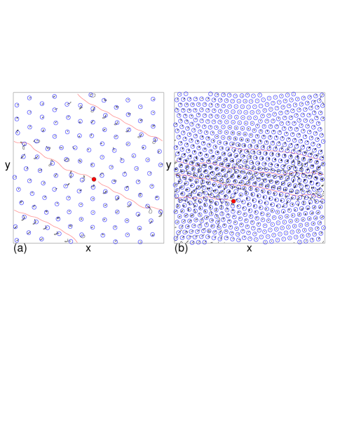
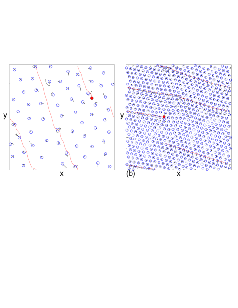
In Fig. 1(a) we show an example of our system for a collection of skyrmions at a density of . The red particle is being driven at a constant force , while the blue particles are the non-driven or bath skyrmions. For this system, , so the ratio between the damping and Magnus forces is close to one. The driven skyrmion moves on average at an angle of . This is smaller in magnitude than the intrinsic skyrmion Hall angle, indicating that collisions with the bath skyrmions are reducing . The magnitude of increases for higher values of but decreases with increasing . Figure 1(b) shows the same system at a higher density of , where the driven skyrmion moves at an even smaller . The skyrmion Hall angle and net velocity depend strongly on the skyrmion density, the driving force, and the ratio of the Magnus force to the damping term.
If the driven skyrmion did not collide with any other skyrmions, it would move at the intrinsic skyrmion Hall angle of with an average absolute velocity of . We first consider systems in which we constrain . Under this condition, we can define a velocity to be the velocity in the single particle limit. Once skyrmion-skyrmion interactions are introduced, in overdamped systems under fixed driving we expect to find . The velocity decreases with increasing and there is a critical density at which .
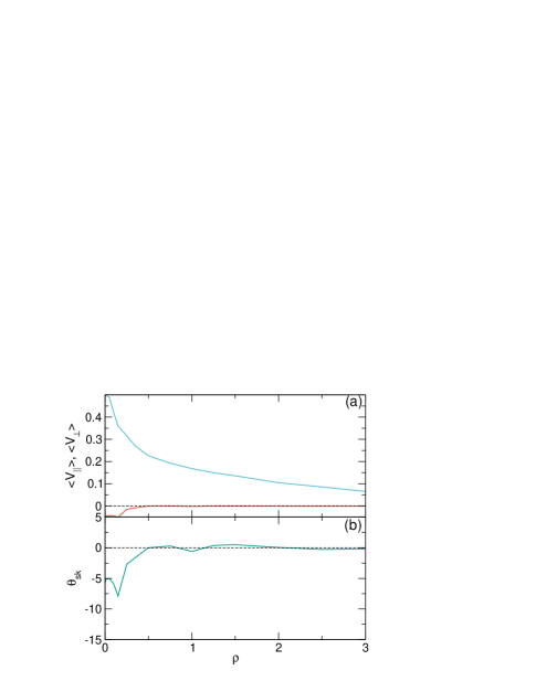
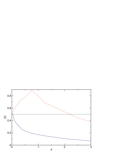
In Fig. 2(a) we plot and versus for a system in the damping dominated regime with , , and . As increases, and both decrease in magnitude and approach zero for . In Fig. 3 we plot for the same system, where the dashed line indicates that for all values of . Here monotonically deceases with increasing , similar to the behavior found in fully overdamped systems. When , , , and has the same shape shown in Fig. 2 but its magnitude is slightly reduced.
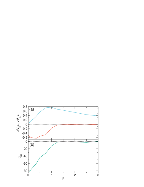
In Fig. 4 we plot , , and versus for the same system from Fig. 2 in the Magnus dominated regime with and . Here the velocities are highly nonmonotonic. initially increases with increasing , reaches a maximum of near , and then decreases again, while has a small initial increase in magnitude followed by a decrease in magnitude to a value of zero near . The Hall angle has the value at low , decreases linearly in magnitude with increasing , and reaches zero for . The maximum value of is higher than , indicating that the velocity in the driving direction is being boosted as the skyrmion density increases. There is also a small boost in near , where . In Fig. 3, the plot of versus for the system in Fig. 4 indicates that reaches a maximum value close to . The dashed line represents , so that a velocity boost is occurring whenever . We observe velocity boosting up to , while for , the net velocity decreases, indicating an increase in the effective damping.
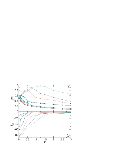
In Fig. 5(a) we plot versus for the systems in Figs. 2 and 4 at , 0.57, 0.98, 2.065, 4.924, 9.95, and . The images in Fig. 1 are taken from the sample with . For , there is no overshoot in and we always find . When , an overshoot emerges with a peak velocity which increases and shifts to larger with increasing Magnus force. Figure 5(b) shows the corresponding versus . In every case, starts at its intrinsic value for small , decreases in magnitude with increasing , and reaches a saturation at high .
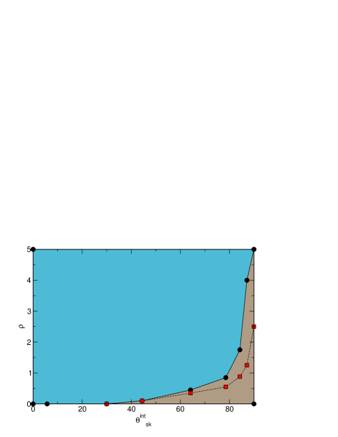
In Fig. 6 we map the regions where a velocity boost is present and absent as a function of versus for the system in Fig. 5. As increases, the upper edge of the velocity boost window shifts to higher values of . The red squares indicate the values of at which the boost of takes its maximum value for each choice of . The boost disappears for all when .
IV Drive Dependence
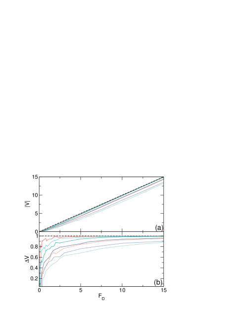
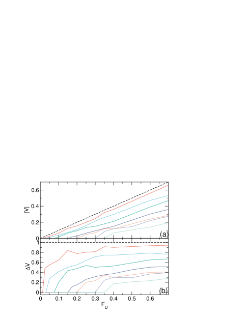
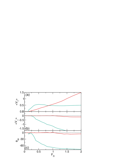
The size of the velocity overshoot and the value of the skyrmion Hall angle at a given skyrmion density is also a function of the magnitude of the driving force. In Fig. 7(a) we plot versus for the system in Fig. 2 with in the damping dominated limit at , 0.1, 0.25, 0.5, 1.0, 1.5, and . The dashed lines indicate the expected behavior in the single particle limit. For any given value of , Fig. 7(a) shows that decreases monotonically with increasing . In Fig. 7(b) we plot versus , where is the velocity in the single particle limit at each value of . When , the driven skyrmion is moving with the same velocity it would have in the single particle limit. indicates increased damping, while is a signature of a boosted velocity. Here we find over the entire range of , indicating that the driven skyrmion is moving slower than the free particle limit. The damping effect is strongest at low drives, and the overall damping increases with increasing . There is also a threshold below which the driven skyrmion does not move, as shown in Fig. 8(a) where we plot a blow up of the low drive region from Fig. 7(a). When , . starts from zero in the single particle limit and increases with increasing . The plot of versus in Fig. 8(b) indicates that is zero below and rises to a saturation value which approaches the single particle limit as decreases. In general, increases towards with increasing since the surrounding skyrmions have less time to respond to a rapidly moving driven skyrmion. For overdamped systems with quenched disorder, the velocity of the probe particle has the power law form , so the particle moves the most slowly just above the threshold depinning force Reichhardt et al. (2021); Fisher (1998); Reichhardt and Reichhardt (2017), while at high drives the velocity generally approaches the pin-free limit Fisher (1998); Reichhardt and Reichhardt (2017). In our system, there is no quenched disorder but the background bath of skyrmions effectively serves as a type of deformable quenched disorder. At high velocities, where the background skyrmions do not have time to respond before the driven skyrmion has passed beyond them, the system looks more like a single skyrmion moving through an array of fixed defects or scattering sites.
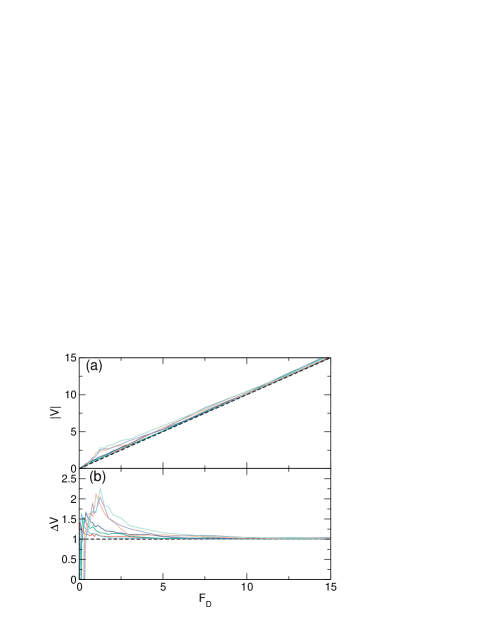
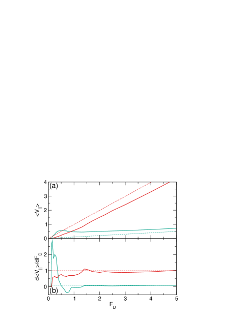
In Fig. 9 we plot and versus for varied in the Magnus dominated regime with and for , 0.1, 0.25, 0.5, 1.0, 1.5, and . The dashed line indicates the expected behavior in the single particle limit. Here we find that is generally larger than the single particle limit, indicating a velocity boost. In Fig. 9(b), increases with increasing and has a peak at which shifts to higher values of as becomes larger. For large , decreases back to the single particle limit. When , the peak value of is almost times larger than the free particle limit. We still observe a threshold force for motion which is almost the same as that found for the overdamped case. In general we do not observe a significant difference in the threshold for motion as a function of the ratio of the Magnus term to the damping. In systems with quenched disorder, it has been shown that the depinning threshold often decreases with increasing Magnus force since the motion of the skyrmions requires a longer time to relax when the Magnus force is larger Reichhardt et al. (2021); Brown et al. (2018). This increases the time required in the presence of disorder for the spiraling motion of the skyrmions to settle into equilibrium after a finite applied drive is increased Reichhardt et al. (2021, 2015a, 2015b); Brown et al. (2019). In our work we apply a constant drive and wait for the system to settle into a steady state. The transient time to reach that state increases near the threshold, suggesting that the observation of a reduced pinning threshold in other studies with quenched disorder could be the result of the increased relaxation time for larger Magnus forces. In studies where the drive is continuously increased from zero to a finite value, the sweeping rate above which transient effects become important should depend on both the damping and Magnus force. Such rate effects will be the subject of a future work.
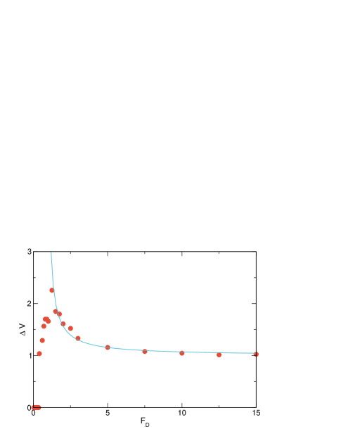
In Fig. 9(b), we find that decreases with increasing drive for and approaches at high drives. The decrease follows the form . In Fig. 10 we plot versus for the specific case of from the system in Fig. 9(b) along with a fit using and . A similar fit can be performed for the other versus curves. This type of dependence on fluctuations or dynamic disorder is also often observed in driven systems with quenched disorder Reichhardt et al. (2021, 2015a, 2015b).
The speed up effect as a function of and arises due to the Magnus force. In systems where a single driven skyrmion interacts with a wall or barrier which is parallel to the direction, an applied drive parallel to the direction generates a skyrmion Hall component which deflects the driven particle in the direction. This increases the skyrmion-wall interaction force in the direction, which results in a perpendicular skyrmion velocity component along the direction. The wall-induced velocity contribution adds to the direction velocity from the driving, generating a velocity boost effect. The magnitude of the boost velocity depends on the nature of the pairwise interaction between the wall and the skyrmion. If the interaction is of the power law form , then as the skyrmion approaches the wall more closely, decreases and the resulting velocity in the direction increases Iwasaki et al. (2014); Zhang et al. (2015); Reichhardt and Reichhardt (2016a); Castell-Queralt et al. (2019); Xing et al. (2020). The boost effect can also occur for skyrmions moving over a two-dimensional periodic substrate Reichhardt et al. (2015a) or over random pinning Gong et al. (2020), since the effect arises whenever the component of the substrate force which is perpendicular to the direction of drive is not balanced by a compensating substrate force in the other direction. This is due to the skyrmion Hall angle which pushes the skyrmion to one side of the pinning sites.
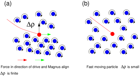
For our single driven skyrmion, there is no pinning or barrier wall; however, a velocity boost effect can still occur due to the creation of a local density gradient in the surrounding medium. The mechanism of this effect is outlined in the schematic of Fig. 11(a), where a driven skyrmion is moving under a finite driving force . For intermediate drives, the skyrmion tries to translate along , which is at a negative angle with respect to the axis. In the process, it displaces some of the surrounding skyrmions in the negative direction, creating a local density imbalance such that the density is higher below the driven skyrmion and lower above it. Due to the repulsive pairwise interactions with the surrounding skyrmions, there is an unbalanced force in the positive direction on the driven skyrmion, as indicated by the black arrow in the schematic. The Magnus term transforms this repulsive force into a velocity in the positive -direction, parallel to the drive, as indicated by the green arrow. Thus, the boost velocity . Here the -direction velocity from the damping term is aligned with but opposite to the velocity induced by the Magnus force. In contrast, when is larger, the surrounding skyrmions do not have time to respond to the rapidly moving driven skyrmion, producing a small and reducing , as shown schematically in Fig. 11(b). For drives that are only slightly above the threshold for motion, the driven skyrmion is moving sufficiently slowly that the surrounding skyrmions have enough time to completely relax any density perturbations, making small. The maximum boost velocity changes as a function of and due to the different relaxation times. In general, at a fixed drive has a damping dependence of and a boost velocity contribution of , where is a function of both the unperturbed density and the drive. For increasing , larger values of can appear but the threshold driving force for the formation of density inhomogeneities also increases. For small , is reduced and the boosting effect is diminished. The boosting effect occurs for any finite value of the Magnus term, but in general only when do we find a regime in which the net velocity is higher than the single particle limit.
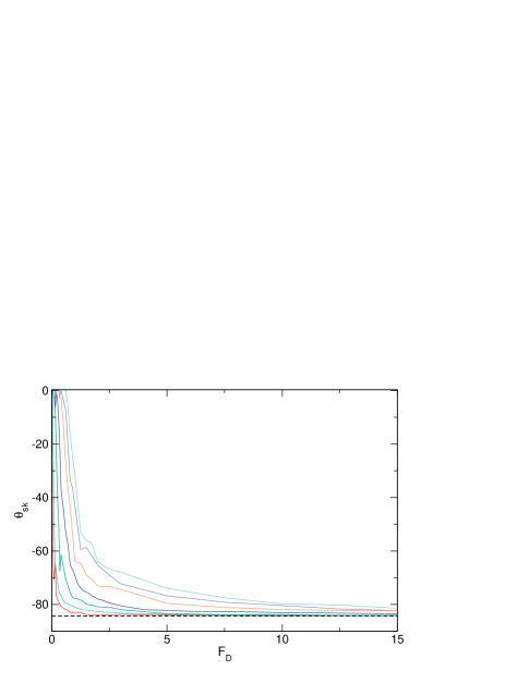
Another effect of the emergence of a density inhomogeneity is a reduction in the skyrmion Hall angle at lower drives, since the skyrmions that accumulate below the driven particle partially block the motion in the direction. In Fig. 12 we plot versus for the system in Fig. 9 with for , 0.1, 0.25, 0.5, 1.0, 1.5, and . The dashed line indicates the single particle limit, where for all values of . We find a finite interval of over which the magnitude of increases with increasing , followed by a saturation close to the intrinsic value at higher drives. As the driven skyrmion approaches the saturation regime, it is moving fast enough that that surrounding skyrmions cannot respond to its presence, giving a small and a reduced boost effect, as shown in Fig. 11(b). The increase of with increasing has also been observed for skyrmion assemblies driven over random disorder, where at higher drives the skyrmions are only weakly perturbed by the pinning Reichhardt et al. (2015a, b); Jiang et al. (2017); Litzius et al. (2017); Reichhardt and Reichhardt (2016b); Legrand et al. (2017); Díaz et al. (2017); Juge et al. (2019); Zeissler et al. (2020); Litzius et al. (2020).
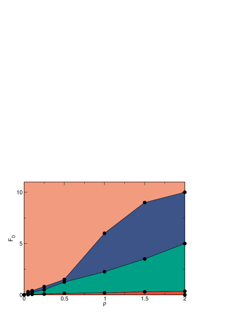
From the features in , , , and , we can construct a dynamic phase diagram as a function of versus for the strongly damped and Magnus dominated limits. In Fig. 13 we show the phase diagram for the damping dominated system with in Figs. 7 and 8. Red indicates the pinned regime where . In the green region, the driven skyrmion is moving but its velocity is strictly along the driving direction so that . In the blue region, there is a finite but growing , while in the orange region, the skyrmion Hall angle has saturated. The thresholds for motion parallel and perpendicular to the driving direction both increase with increasing . Previous work in systems with quenched disorder also showed that there can be separate thresholds for the onset of motion parallel and perpendicular to the drive, with a region above the first depinning threshold where the skyrmions can flow at for small intrinsic skyrmion Hall angles Jiang et al. (2017); Reichhardt and Reichhardt (2019b, 2021). As the ratio of the Magnus force to the damping term increases, the threshold for transverse motion shifts to smaller . In the saturation regime, the response resembles the single particle limit and approaches the intrinsic skyrmion Hall value of .
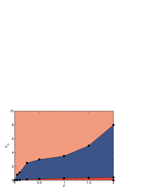
In Fig. 14 we show the dynamic phase diagram as a function of versus for the Magnus dominated system with . There is still a pinned regime, but the region in which there is finite motion with is absent or too small to detect. In the blue region, the velocity is significantly boosted beyond the single particle limit and the skyrmion Hall angle increases with increasing drive. In the orange region, both and the velocity approach the single particle limit. Between the damping dominated and Magnus dominated limits, the dynamic phase diagram includes a combination of the features of the phase diagrams in Fig. 13 and Fig. 14.
V Varied Magnus to Damping Ratio and Velocity-Force Curves
We next fix the density and vary the ratio of the Magnus and damping terms while maintaining the normalization relation . In Fig. 15(a) we plot versus for systems with at and . Figures 15(b) and (c) show the corresponding values of and versus , respectively. For the Magnus dominated case of , and become finite at almost the same value of , which also corresponds to the appearance of a nonzero . For the damping dominated sample with , and remain zero up to .
The ratio of the Magnus to the damping term determines the shape of the velocity-force curves. For , both and increase monotonically with according to the linear behavior , where is the threshold for motion in either the parallel or the perpendicular direction. When , still increases linearly with increasing above the depinning threshold; however, exhibits a nonmonotonic behavior in which it initially rises rapidly with increasing but then decreases again. In this regime, the velocity decreases even though the drive is increasing, giving , which is known as negative differential conductivity Reichhardt and Reichhardt (2017). In Fig. 16(a) we plot versus for the samples from Fig. 15. The green dashed line shows the expected value for in the single particle limit at , which increases linearly according to . For the sample, the red dashed line is the single particle limit . In the damping dominated system with , is below the single particle limit, while in the Magnus dominated system with , is higher than the single particle limit due to the boosting effect. In Fig. 16(b) we show the corresponding values of , with the single particle limits marked by dashed lines. For the system, the initial peak in corresponding to the depinning transition is followed by a region of negative differential conductivity where . At higher drives, saturates to the value expected in the single particle limit. For the damping dominated system with , is initially below the single particle value due to the increased damping from the surrounding skyrmions, while at higher drives it approaches the single particle limit. The negative differential conductivity in the Magnus-dominated system is affected by the density, and for low the shape of the velocity-force curve approaches that found in the single particle limit.
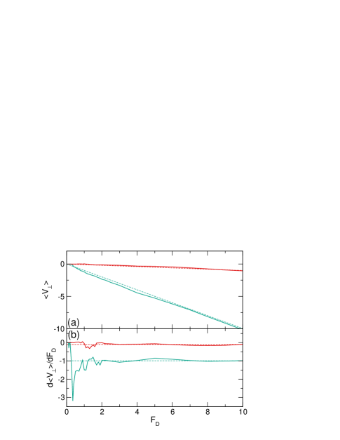
In Fig. 17(a) we plot versus for the system in Fig. 15 at with and . The dashed lines are the expected values for the single particle limit, which obey for the system and for the system. In the Magnus dominated regime, is slightly larger than it would be in the single particle limit, while in the damping dominated regime it is slightly lower. Most of the velocity boost in the Magnus dominated regime is parallel to the driving direction since the induced density gradient is perpendicular to the drive. In Fig. 17(b) we show the corresponding versus curves where, unlike the parallel velocity plotted in Fig. 16, there is no regime of negative differential mobility. There is still a peak in near the depinning threshold, while at high drives the curves approach the single particle limit.
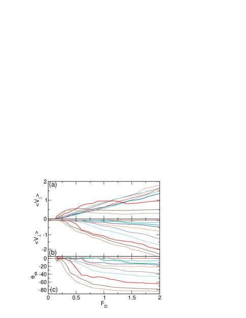
In Fig. 18(a) we plot versus for the system in Fig. 15 with fixed and at , 0.1, 0.3, 0.5, 0.7, 0.8, 0.9, 0.97, 0.995, and . Figures 18(b) and (c) show the corresponding and , respectively, versus . We find negative differential conductivity for or , indicating that this effect appears only when the Magnus force is sufficiently large. There is no negative differential conductivity in the versus curves, while the plots of versus indicate that as decreases, the threshold drive above which the skyrmion Hall angle becomes finite increases.
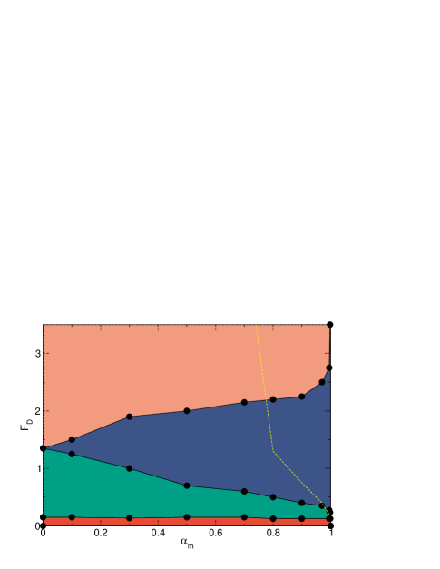
From the features in Fig. 18 we can construct a dynamic phase diagram as a function of versus , as shown in Fig. 19. Here we outline the pinned phase, the flowing regime with , the region in which increases with increasing , and the saturation regime where there is little change in . For drives above the dashed line, the velocities are boosted compared to the single particle limit. The boost is strongly reduced in the saturation regime. Figure 19 indicates that the depinning threshold is approximately constant as a function of increasing , while the regime in which the velocity is locked in the driving direction grows in extent with decreasing . At , the onset of saturation coincides with the point where the velocity-force curves start to grow linearly with . The transition demarcating the onset of a velocity boost shifts to lower as increases.
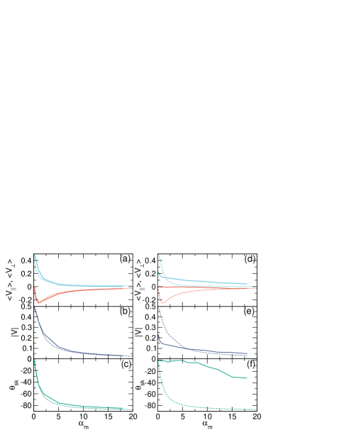
We next relax the constraint of and instead hold either the Magnus or damping term constant while varying the other quantity. For a fixed drive, this means that in the single particle limit, obeys . In Fig. 20(a) we plot and versus for a system with , , and . Here is zero for , increases to a maximum value near , and then decreases with increasing , while gradually approaches zero as increases. In the single particle limit, and , so for a fixed , , plotted as a dashed line. In this case, when , and the parallel velocity also approaches zero at large . Similarly, in the single particle limit, , so that when , . For , the density is low enough that the behavior is close to the single particle limit. In Fig. 20(b) we plot versus for the system in Fig. 20(a), where the dashed line is the single particle limit of . There is a small boost in for , while drops below the free particle limit for . Figure 20(c) shows the corresponding versus for the system, where the magnitude of gradually decreases with increasing . The dashed line is the single particle limit, . The measured skyrmion Hall angle is smaller in magnitude than the single particle value due to the collisions with the background skyrmions. In Fig. 21(a) we show the positions and trajectories of the driven skyrmion and the background skyrmions for the system in Fig. 20(a) at and . The driven skyrmion is moving at a skyrmion Hall angle close to . Although there are some collisions with the background skyrmions, there is only a small boost in the velocity.
In Fig. 20(d) we show and versus for the same system in Fig. 20(a) but at a higher density of . The dashed lines are the expected behavior in the single particle limit. Here there is a boost in for , while drops below the single particle limit at higher . There is also a small boost in for . We note that unlike the low density case, is finite at due to collisions with the background skyrmions. Figure 20(e) shows the corresponding versus and the expected single particle limit, indicating that there is a net velocity boost for followed by increased damping for . In Fig. 20(f) we plot the corresponding versus and the single particle limit. The skyrmion Hall angle rapidly decreases in magnitude with increasing , reaching a saturation for . Figure 21(b) shows the positions and trajectories of the driven and bath skyrmions for the system in Fig. 20(d) at and , where the skyrmion Hall angle is much smaller than that found in the system illustrated in Fig. 21(a); however, the velocity of the driven skyrmion is much larger for the system.
In Fig. 22(a) we plot and versus for a system with fixed , , and . In the single particle limit with , and . We find that monotonically decreases and changes from being slightly higher than the free particle limit for to being slightly lower than the free particle limit for . starts from zero at , reaches a maximum value near , and gradually drops back to zero with increasing , closely following the single particle limit. In Fig. 22(b) we show the corresponding versus along with a dashed line indicating the single particle limit of , which decreases monotonically with increasing . There is a small boost in the velocity due to the collisions with the background skyrmions. Figure 21(c) shows versus for the same system as well as the single particle limit of . Here the measured skyrmion Hall angle is slightly smaller in magnitude than the single particle limit due to the collisions with bath skyrmions.
In Fig. 22(d) we plot , , and the single particle limits for the same system from Fig. 22(a) but at a higher density of . Here is considerably below the single particle limit at due to the increased frequency of collisions; however, for , it is considerately higher than the single particle limit. is close to zero for but begins to increase at larger . In Fig. 22(e) we show the corresponding versus . falls below the dashed line representing the single particle limit up to and exhibits a boost for higher . Figure 22(f) illustrates the corresponding versus and the single particle limit. is close to zero for , while for higher , the magnitude of increases and a velocity boost appears. For higher values of , all of the quantities gradually approach the single particle limit.
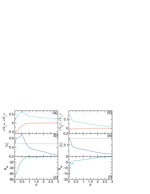
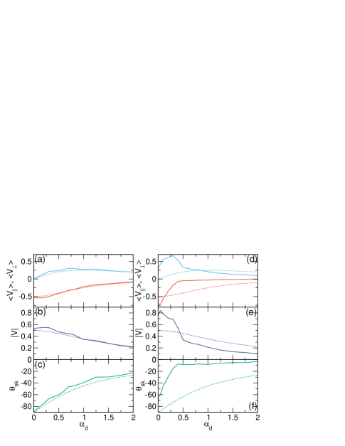
In Fig. 23(a) we plot and versus for a system with fixed , , and . The single particle limit for these parameters gives and . initially increases with increasing to a peak value of , a strong boost that is four times larger than the single particle limit. As increases further, gradually decreases; however, even at the high density of , is still almost twice as large as the single particle limit, indicating the continuing effectiveness of the boost effect. decreases monotonically in magnitude with increasing density, approaching a value close to zero for . In Fig. 23(b) we show the corresponding versus , where the dashed line is the single particle limit of which for these coefficients is . Here there is a boost in the velocity up to , while at higher densities the velocities are much more strongly damped. This indicates that it is possible for the parallel velocity to be boosted while the overall velocity is not boosted. Figure 23(c) illustrates the corresponding versus . For low density, the skyrmion Hall angle is near the intrinsic value of , and as increases, approaches zero once .
In Fig. 23(d) we plot and versus for a system with a larger at and . For these parameters, the single particle limit gives and . We find that both and monotonically decrease in magnitude with increasing . In Fig. 23(e) we show the corresponding versus , where the dashed line is the single particle limit of . Here there is no boost and drops off rapidly with increasing , showing a change in slope near to a slower decline. Figure 23(f) illustrates the corresponding versus , which starts off near and approaches zero for . The change in the skyrmion Hall angle and velocity across occurs because the density is low enough for that the bath skyrmions act like a fluid which is not strongly coupled to the driven skyrmion, while when , the bath skyrmions act more like a solid, increasing the drag on the driven skyrmion.
VI Discussion
In our work, the driven skyrmion is free to move in any direction. In certain chiral soft matter systems, a similar probe particle could be implemented using a magnetic or charged particle coupled to a uniform magnetic or electric field which does not couple to the remaining particles, allowing the probe particle to move at any angle. In skyrmion systems, it is possible to have samples containing multiple species of skyrmions, some of which could couple more strongly than others to an externally imposed field. The closest experimental realization of our system for skyrmions would be to drag a single skyrmion using some form of localized trap. Such an arrangement would constrain the driven skyrmion to move only in the direction the trap is being translated, and would not allow the driven skyrmion to move at a speed greater than that of the trap. In this case, changes in the effective viscosity could be deduced by measuring the force or the fluctuations exerted by the skyrmion on the trap. The case of a trap moving at a constant velocity will be studied in another work; however, the results of the present study can be used as a guide to understand which different velocity regimes could arise.
In our work we have only considered a particle-based model, which neglects internal degrees of freedom and shape changes of the skyrmion. Such modes could increase or decrease the damping experienced by the driven skyrmion or change the nature of the skyrmion motion. We have also assumed a simple pairwise repulsion between skyrmions, but it is possible for skyrmions to have more complex interactions, such as competing interactions at different length scales. This could produce additional coupling/decoupling or depinning transitions.
In constant velocity experiments, the force the skyrmion experiences could have a periodic signature if the motion occurs through a skyrmion solid, or a broad band noise signature if the skyrmion is moving through a glass or liquid state. Numerical work Reichhardt and Reichhardt (2016b); Díaz et al. (2017) and experiments Sato et al. (2019, 2020) on collectively moving skyrmions have shown the presence of both broad and narrow band noise, so it would be interesting to study the fluctuations exerted on a single skyrmion as it moves through a bath of other skyrmions. We can also compare our results to active rheology in overdamped chiral granular systems, where a disk with short range repulsive interactions is pushed through an assembly of spinning grains Reichhardt and Reichhardt (2019a). The granular system generally does not exhibit any velocity boost due to its overdamped nature. The probe particle in the granular system has no intrinsic Hall angle, but as function of driving force shows a finite Hall angle at intermediate drives, with no Hall angle at low or high drives. The finite Hall angle arises as a result of collisions between the probe particle and the spinning disks, which create a deflection of the probe particle perpendicular to the driving direction. This deflection decreases in magnitude as the velocity of the probe particle increases.
VII Summary
We have numerically examined the active rheology of a single skyrmion driven through a bath of other skyrmions in the absence of quenched disorder. Active rheology has been used to study the changes in drag on driven probe particles in various soft matter and superconducting vortex systems where the dynamics is overdamped. In those systems, the velocity of the probe particle under a constant driving force rapidly decreases with increasing bath particle density due to an increased dragging effect. For skyrmions, which have a strong Magnus force, we find that the behavior differs strongly from what is observed in the damping dominated limit. The driven skyrmion velocity in the driving direction is highly non-monotonic as a function of density, and can increase rather than decreasing when the density is increased. This effect appears as a boost in the net velocity. At higher densities, the velocity decreases with increasing density. The skyrmion Hall angle also decreases as the bath density increases. The magnitude of the velocity boost depends on the system density, the strength of the Magnus term, and the applied drive. For a fixed density, as we increase the driving force we find a critical threshold force below which the driven skyrmion does not move, a regime in which the magnitude of the skyrmion Hall angle increases with drive, and a regime at higher drive where the skyrmion Hall angle saturates. The drive dependence of the skyrmion Hall angle is similar to that observed for skyrmions driven over quenched disorder. If the Magnus force is dominant, a velocity boost appears which is maximum for an intermediate drive and diminishes at higher drives. When the damping force is strong, the velocities are reduced but approach the single particle limit at higher drives. The velocity-force curves in the damped regime have linear or monotonic behavior, while in the Magnus dominated regime, the velocity in the driving direction can decrease with increasing drive, leading to negative differential conductivity. The maximum velocity boost shifts to higher drives with increased density. The velocity boost originates when the driven skyrmion moves at a finite skyrmion Hall angle and creates a localized density inhomogeneity in the background skyrmions, which generate an unbalanced pairwise repulsive force on the driven skyrmion perpendicular to the driving direction. The Magnus force then converts this force into an additional velocity component in the direction of drive. At low bath densities, the localized density fluctuation relaxes quickly and the velocity boost is small, while at high drives the driven skyrmion moves too quickly past the bath skyrmions for a localized density fluctuation to form, so the velocity boost is again reduced. We find regimes in which the skyrmion Hall angle decreases with a simultaneous increase in the skyrmion velocity, suggesting that skyrmion-skyrmion interactions can be useful for producing effects that are of value for use in devices. We discuss possible experimental realizations of this system where a single skyrmion could be driven with some form of tip or optical trap while deflection forces on the skyrmion are measured. Beyond skyrmions, our results should be relevant to any kind of active rheology in systems with gyroscopic forces, such as active chiral matter, fluid vortices, electrons in a magnetic field, fractons, and other gyroscopic systems.
Acknowledgements.
We gratefully acknowledge the support of the U.S. Department of Energy through the LANL/LDRD program for this work. This work was supported by the US Department of Energy through the Los Alamos National Laboratory. Los Alamos National Laboratory is operated by Triad National Security, LLC, for the National Nuclear Security Administration of the U. S. Department of Energy (Contract No. 892333218NCA000001).References
- Mühlbauer et al. (2009) S. Mühlbauer, B. Binz, F. Jonietz, C. Pfleiderer, A. Rosch, A. Neubauer, R. Georgii, and P. Böni, “Skyrmion lattice in a chiral magnet,” Science 323, 915–919 (2009).
- Yu et al. (2010) X. Z. Yu, Y. Onose, N. Kanazawa, J. H. Park, J. H. Han, Y. Matsui, N. Nagaosa, and Y. Tokura, “Real-space observation of a two-dimensional skyrmion crystal,” Nature (London) 465, 901–904 (2010).
- Nagaosa and Tokura (2013) N. Nagaosa and Y. Tokura, “Topological properties and dynamics of magnetic skyrmions,” Nature Nanotechnol. 8, 899–911 (2013).
- Everschor-Sitte et al. (2018) K. Everschor-Sitte, J. Masell, R. M. Reeve, and M. Klaüi, “Perspective: Magnetic skyrmions - Overview of recent progress in an active research field,” J. Appl. Phys. 124, 240901 (2018).
- Reichhardt et al. (2021) C. Reichhardt, C. J. O. Reichhardt, and M. V. Milosevic, “Statics and dynamics of skyrmions interacting with pinning: a review,” arXiv e-prints , arXiv:2102.10464 (2021).
- Woo et al. (2016) S. Woo, K. Litzius, B. Krüger, M.-Y. Im, L. Caretta, K. Richter, M. Mann, A. Krone, R. M. Reeve, M. Weigand, P. Agrawal, I. Lemesh, M.-A. Mawass, P. Fischer, M. Kläui, and G. S. D. Beach, “Observation of room-temperature magnetic skyrmions and their current-driven dynamics in ultrathin metallic ferromagnets,” Nature Mater. 15, 501 (2016).
- Soumyanarayanan et al. (2017) A. Soumyanarayanan, M. Raju, A. L. G. Oyarce, A. K. C. Tan, M.-Y. Im, A. P. Petrovic, P. Ho, K. H. Khoo, M. Tran, C. K. Gan, F. Ernult, and C. Panagopoulos, “Tunable room-temperature magnetic skyrmions in Ir/Fe/Co/Pt multilayers,” Nature Mater. 16, 898 (2017).
- Montoya et al. (2018) S. A. Montoya, R. Tolley, I. Gilbert, S.-G. Je, M.-Y. Im, and E. E. Fullerton, “Spin-orbit torque induced dipole skyrmion motion at room temperature,” Phys. Rev. B 98, 104432 (2018).
- Jonietz et al. (2010) F. Jonietz, S. Mühlbauer, C. Pfleiderer, A. Neubauer, W. Münzer, A. Bauer, T. Adams, R. Georgii, P. Böni, R. A. Duine, K. Everschor, M. Garst, and A. Rosch, “Spin transfer torques in MnSi at ultralow current densities,” Science 330, 1648–1651 (2010).
- Yu et al. (2012) X. Z. Yu, N. Kanazawa, W. Z. Zhang, T. Nagai, T. Hara, K. Kimoto, Y. Matsui, Y. Onose, and Y. Tokura, “Skyrmion flow near room temperature in an ultralow current density,” Nature Commun. 3, 988 (2012).
- Iwasaki et al. (2013) J. Iwasaki, M. Mochizuki, and N. Nagaosa, “Universal current-velocity relation of skyrmion motion in chiral magnets,” Nature Commun. 4, 1463 (2013).
- Zhang et al. (2018) S. L. Zhang, W. W. Wang, D. M. Burn, H. Peng, H. Berger, A. Bauer, C. Pfleiderer, G. van der Laan, and T. Hesjedal, “Manipulation of skyrmion motion by magnetic field gradients,” Nature Commun. 9, 2115 (2018).
- Mochizuki et al. (2014) M. Mochizuki, X. Z. Yu, S. Seki, N. Kanazawa, W. Koshibae, J. Zang, M. Mostovoy, Y. Tokura, and N. Nagaosa, “Thermally driven ratchet motion of a skyrmion microcrystal and topological magnon Hall effect,” Nature Mater. 13, 241–246 (2014).
- Fert et al. (2013) A. Fert, V. Cros, and J. Sampaio, “Skyrmions on the track,” Nature Nanotechnol. 8, 152–156 (2013).
- Tomasello et al. (2014) R. Tomasello, E. Martinez, R. Zivieri, L. Torres, M. Carpentieri, and G. Finocchio, “A strategy for the design of skyrmion racetrack memories,” Sci. Rep. 4, 6784 (2014).
- Fert et al. (2017) A. Fert, N. Reyren, and V. Cros, “Magnetic skyrmions: advances in physics and potential applications,” Nature Rev. Mater. 2, 17031 (2017).
- Zázvorka et al. (2019) J. Zázvorka, F. Jakobs, D. Heinze, N. Keil, S. Kromin, S. Jaiswal, K. Litzius, G. Jakob, P. Virnau, D. Pinna, K. Everschor-Sitte, L. Rózsa, A. Donges, U. Nowak, and M. Kläui, “Thermal skyrmion diffusion used in a reshuffler device,” Nature Nanotechnol. 14, 658–661 (2019).
- Zhang et al. (2020) H. Zhang, D. Zhu, W. Kang, Y. Zhang, and W. Zhao, “Stochastic computing implemented by skyrmionic logic devices,” Phys. Rev. Applied 13, 054049 (2020).
- Pinna et al. (2020) D. Pinna, G. Bourianoff, and K. Everschor-Sitte, “Reservoir computing with random skyrmion textures,” Phys. Rev. Applied 14, 054020 (2020).
- Fisher (1998) D. S. Fisher, “Collective transport in random media: from superconductors to earthquakes,” Phys. Rep. 301, 113–150 (1998).
- Reichhardt and Reichhardt (2017) C. Reichhardt and C. J. Olson Reichhardt, “Depinning and nonequilibrium dynamic phases of particle assemblies driven over random and ordered substrates: a review,” Rep. Prog. Phys. 80, 026501 (2017).
- Bhattacharya and Higgins (1993) S. Bhattacharya and M. J. Higgins, “Dynamics of a disordered flux line lattice,” Phys. Rev. Lett. 70, 2617–2620 (1993).
- Blatter et al. (1994) G. Blatter, M. V. Feigel’man, V. B. Geshkenbein, A. I. Larkin, and V. M. Vinokur, “Vortices in high-temperature superconductors,” Rev. Mod. Phys. 66, 1125–1388 (1994).
- Tierno (2012) P. Tierno, “Depinning and collective dynamics of magnetically driven colloidal monolayers,” Phys. Rev. Lett. 109, 198304 (2012).
- Reichhardt et al. (2001) C. Reichhardt, C. J. Olson, N. Grønbech-Jensen, and F. Nori, “Moving Wigner glasses and smectics: Dynamics of disordered Wigner crystals,” Phys. Rev. Lett. 86, 4354–4357 (2001).
- Vanossi et al. (2013) A. Vanossi, N. Manini, M. Urbakh, S. Zapperi, and E. Tosatti, “Colloquium: Modeling friction: From nanoscale to mesoscale,” Rev. Mod. Phys. 85, 529–552 (2013).
- O’Hern et al. (2003) C. S. O’Hern, L. E. Silbert, A. J. Liu, and S. R. Nagel, “Jamming at zero temperature and zero applied stress: The epitome of disorder,” Phys. Rev. E 68, 011306 (2003).
- Everschor-Sitte and Sitte (2014) K. Everschor-Sitte and M. Sitte, “Real-space Berry phases: Skyrmion soccer (invited),” J. Appl. Phys. 115, 172602 (2014).
- Reichhardt et al. (2015a) C. Reichhardt, D. Ray, and C. J. Olson Reichhardt, “Quantized transport for a skyrmion moving on a two-dimensional periodic substrate,” Phys. Rev. B 91, 104426 (2015a).
- Reichhardt et al. (2015b) C. Reichhardt, D. Ray, and C. J. Olson Reichhardt, “Collective transport properties of driven skyrmions with random disorder,” Phys. Rev. Lett. 114, 217202 (2015b).
- Jiang et al. (2017) W. Jiang, X. Zhang, G. Yu, W. Zhang, X. Wang, M. B. Jungfleisch, J. E. Pearson, X. Cheng, O. Heinonen, K. L. Wang, Y. Zhou, A. Hoffmann, and S. G. E. te Velthuis, “Direct observation of the skyrmion Hall effect,” Nature Phys. 13, 162–169 (2017).
- Litzius et al. (2017) K. Litzius, I. Lemesh, B. Krüger, P. Bassirian, L. Caretta, K. Richter, F. Büttner, K. Sato, O. A. Tretiakov, J. Förster, R. M. Reeve, M. Weigand, L. Bykova, H. Stoll, G. Schütz, G. S. D. Beach, and M. Kläui, “Skyrmion Hall effect revealed by direct time-resolved X-ray microscopy,” Nature Phys. 13, 170–175 (2017).
- Iwasaki et al. (2014) J. Iwasaki, W. Koshibae, and N. Nagaosa, “Colossal spin transfer torque effect on skyrmion along the edge,” Nano Lett. 14, 4432 (2014).
- Zhang et al. (2015) X. Zhang, G. P. Zhao, H. Fangohr, J. P. Liu, W. X. Xia, J. Xia, and F. J. Morvan, “Skyrmion-skyrmion and skyrmion-edge repulsions in skyrmion-based racetrack memory,” Sci. Rep. 5, 7643 (2015).
- Reichhardt and Reichhardt (2016a) C. Reichhardt and C. J. Olson Reichhardt, “Magnus-induced dynamics of driven skyrmions on a quasi-one-dimensional periodic substrate,” Phys. Rev. B 94, 094413 (2016a).
- Castell-Queralt et al. (2019) J. Castell-Queralt, L. Gonzalez-Gomez, N. Del-Valle, A. Sanchez, and C. Navau, “Accelerating, guiding, and compressing skyrmions by defect rails,” Nanoscale 11, 12589–12594 (2019).
- Xing et al. (2020) X. Xing, J. Åkerman, and Y. Zhou, “Enhanced skyrmion motion via strip domain wall,” Phys. Rev. B 101, 214432 (2020).
- Reichhardt et al. (2015c) C. Reichhardt, D. Ray, and C. J. Olson Reichhardt, “Magnus-induced ratchet effects for skyrmions interacting with asymmetric substrates,” New J. Phys. 17, 073034 (2015c).
- Ma et al. (2017) X. Ma, C. J. Olson Reichhardt, and C. Reichhardt, “Reversible vector ratchets for skyrmion systems,” Phys. Rev. B 95, 104401 (2017).
- Chen et al. (2020) W. Chen, L. Liu, and Y. Zheng, “Ultrafast ratchet dynamics of skyrmions by defect engineering in materials with poor conductivity under gigahertz magnetic fields,” Phys. Rev. Applied 14, 064014 (2020).
- Göbel and Mertig (2021) B. Göbel and I. Mertig, “Skyrmion ratchet propagation: utilizing the skyrmion Hall effect in AC racetrack storage devices,” Sci. Rep. 11, 3020 (2021).
- Büttner et al. (2015) F. Büttner, C. Moutafis, M. Schneider, B. Krüger, C. M. Günther, J. Geilhufe, C. von Kor Schmising, J. Mohanty, B. Pfau, S. Schaffert, A. Bisig, M. Foerster, T. Schulz, C. A. F. Vaz, J. H. Franken, H. J. M. Swagten, M. Kläui, and S. Eisebitt, “Dynamics and inertia of skyrmionic spin structures,” Nature Phys. 11, 225–228 (2015).
- Fernandes et al. (2020) I. L. Fernandes, J. Chico, and S. Lounis, “Impurity-dependent gyrotropic motion, deflection and pinning of current-driven ultrasmall skyrmions in pdfe/ir(111) surface,” J. Phys.: Condens. Matter 32, 425802 (2020).
- Brown et al. (2018) B. L. Brown, U. C. Täuber, and M. Pleimling, “Effect of the Magnus force on skyrmion relaxation dynamics,” Phys. Rev. B 97, 020405 (2018).
- Hanneken et al. (2016) C. Hanneken, A. Kubetzka, K. von Bergmann, and R. Wiesendanger, “Pinning and movement of individual nanoscale magnetic skyrmions via defects,” New J. Phys. 18, 055009 (2016).
- Wang et al. (2017) C. Wang, D. Xiao, X. Chen, Y. Zhou, and Y. Liu, “Manipulating and trapping skyrmions by magnetic field gradients,” New J. Phys. 19, 083008 (2017).
- Casiraghi et al. (2019) A. Casiraghi, H. Corte-León, M. Vafaee, F. Garcia-Sanchez, G. Durin, M. Pasquale, G. Jakob, M. Kläui, and O. Kazakova, “Individual skyrmion manipulation by local magnetic field gradients,” Commun. Phys. 2, 145 (2019).
- Wang et al. (2020) X.-G. Wang, L. Chotorlishvili, V. K. Dugaev, A. Ernst, I. V. Maznichenko, N. Arnold, C. Jia, J. Berakdar, I. Mertig, and J. Barnas̀, “The optical tweezer of skyrmions,” npj Comput. Mater. 6, 140 (2020).
- Hastings et al. (2003) M. B. Hastings, C. J. Olson Reichhardt, and C. Reichhardt, “Depinning by fracture in a glassy background,” Phys. Rev. Lett. 90, 098302 (2003).
- Habdas et al. (2004) P. Habdas, D. Schaar, A. C. Levitt, and E. R. Weeks, “Forced motion of a probe particle near the colloidal glass transition,” Europhys. Lett. 67, 477–483 (2004).
- Squires and Brady (2005) T. M. Squires and J. F. Brady, “A simple paradigm for active and nonlinear microrheology,” Phys. Fluids 17, 073101 (2005).
- Gazuz et al. (2009) I. Gazuz, A. M. Puertas, Th. Voigtmann, and M. Fuchs, “Active and nonlinear microrheology in dense colloidal suspensions,” Phys. Rev. Lett. 102, 248302 (2009).
- Winter et al. (2012) D. Winter, J. Horbach, P. Virnau, and K. Binder, “Active nonlinear microrheology in a glass-forming Yukawa fluid,” Phys. Rev. Lett. 108, 028303 (2012).
- Drocco et al. (2005) J. A. Drocco, M. B. Hastings, C. J. Olson Reichhardt, and C. Reichhardt, “Multiscaling at point : Jamming is a critical phenomenon,” Phys. Rev. Lett. 95, 088001 (2005).
- Candelier and Dauchot (2010) R. Candelier and O. Dauchot, “Journey of an intruder through the fluidization and jamming transitions of a dense granular media,” Phys. Rev. E 81, 011304 (2010).
- Olson Reichhardt and Reichhardt (2010) C. J. Olson Reichhardt and C. Reichhardt, “Fluctuations, jamming, and yielding for a driven probe particle in disordered disk assemblies,” Phys. Rev. E 82, 051306 (2010).
- Kolb et al. (2013) E. Kolb, P. Cixous, N. Gaudouen, and T. Darnige, “Rigid intruder inside a two-dimensional dense granular flow: Drag force and cavity formation,” Phys. Rev. E 87, 032207 (2013).
- Reichhardt and Reichhardt (2019a) C. Reichhardt and C. J. O. Reichhardt, “Active microrheology, Hall effect, and jamming in chiral fluids,” Phys. Rev. E 100, 012604 (2019a).
- Reichhardt and Reichhardt (2015) C. Reichhardt and C. J. Olson Reichhardt, “Active microrheology in active matter systems: Mobility, intermittency, and avalanches,” Phys. Rev. E 91, 032313 (2015).
- Straver et al. (2008) E. W. J. Straver, J. E. Hoffman, O. M. Auslaender, D. Rugar, and K. A. Moler, “Controlled manipulation of individual vortices in a superconductor,” Appl. Phys. Lett. 93, 172514 (2008).
- Reichhardt (2009) C. Reichhardt, “Vortices wiggled and dragged,” Nature Phys. 5, 15–16 (2009).
- Auslaender et al. (2009) O. M. Auslaender, L. Luan, E. W. J. Straver, J. E. Hoffman, N. C. Koshnick, E. Zeldov, D. A. Bonn, R. Liang, W. N. Hardy, and K. A. Moler, “Mechanics of individual isolated vortices in a cuprate superconductor,” Nature Phys. 5, 35–39 (2009).
- Veshchunov et al. (2016) I. S. Veshchunov, W. Magrini, S. V. Mironov, A. G. Godin, J. B. Trebbia, A. I. Buzdin, Ph. Tamarat, and B. Lounis, “Optical manipulation of single flux quanta,” Nature Commun. 7, 12801 (2016).
- Kremen et al. (2016) A. Kremen, S. Wissberg, N. Haham, E. Persky, Y. Frenkel, and B. Kalisky, “Mechanical control of individual superconducting vortices,” Nano Lett. 16, 1626–1630 (2016).
- Crassous et al. (2011) A. Crassous, R. Bernard, S. Fusil, K. Bouzehouane, D. Le Bourdais, S. Enouz-Vedrenne, J. Briatico, M. Bibes, A. Barthélémy, and J. E. Villegas, “Nanoscale electrostatic manipulation of magnetic flux quanta in ferroelectric/superconductor BiFeO3/YBa2Cu3O7-δ heterostructures,” Phys. Rev. Lett. 107, 247002 (2011).
- Olson Reichhardt and Reichhardt (2008) C. J. Olson Reichhardt and C. Reichhardt, “Viscous decoupling transitions for individually dragged particles in systems with quenched disorder,” Phys. Rev. E 78, 011402 (2008).
- Wulfert et al. (2017) R. Wulfert, U. Seifert, and T. Speck, “Nonequilibrium depletion interactions in active microrheology,” Soft Matter 13, 9093 (2017).
- Zia (2018) R. N. Zia, “Active and passive microrheology: Theory and simulation,” Ann. Rev. Fluid Mech. 50, 371 (2018).
- Wang et al. (2019) H. Wang, T. Mohorič, X. Zhang, J. Dobnikar, and J. Horbach, “Active microrheology in two-dimensional magnetic networks,” Soft Matter 15, 4437 (2019).
- Yu et al. (2020) J. W. Yu, S. H. E. Rahbari, T. Kawasaki, H. Park, and W. B. Lee, “Active microrheology of a bulk metallic glass,” Sci. Adv. 6 (2020), 10.1126/sciadv.aba8766.
- Reichhardt and Reichhardt (2004) C. Reichhardt and C. J. Olson Reichhardt, “Local melting and drag for a particle driven through a colloidal crystal,” Phys. Rev. Lett. 92, 108301 (2004).
- Dullens and Bechinger (2011) R. P. A. Dullens and C. Bechinger, “Shear thinning and local melting of colloidal crystals,” Phys. Rev. Lett. 107, 138301 (2011).
- Şenbil et al. (2019) N. Şenbil, M. Gruber, C. Zhang, M. Fuchs, and F. Scheffold, “Observation of strongly heterogeneous dynamics at the depinning transition in a colloidal glass,” Phys. Rev. Lett. 122, 108002 (2019).
- Gruber et al. (2020) M. Gruber, A. M. Puertas, and M. Fuchs, “Critical force in active microrheology,” Phys. Rev. E 101, 012612 (2020).
- Benichou et al. (2013) O. Benichou, P. Illien, C. Mejia-Monasterio, and G. Oshanin, “A biased intruder in a dense quiescent medium: looking beyond the force-velocity relation,” J. Stat. Mech. 2013, P05008 (2013).
- Illien et al. (2018) P. Illien, O. Bénichou, G. Oshanin, A. Sarracino, and R. Voituriez, “Nonequilibrium fluctuations and enhanced diffusion of a driven particle in a dense environment,” Phys. Rev. Lett. 120, 200606 (2018).
- Kokot et al. (2017) G. Kokot, S. Das, R. G. Winkler, G. Gompper, I. S. Aranson, and A. Snezhko, “Active turbulence in a gas of self-assembled spinners,” Proc. Natl. Acad. Sci. (USA) 114, 12870–12875 (2017).
- Banerjee et al. (2017) D. Banerjee, A. Souslov, A. G. Abanov, and V. Vitelli, “Odd viscosity in chiral active fluids,” Nature Commun. 8, 1573 (2017).
- Soni et al. (2019) V. Soni, E. S. Bililign, S. Magkiriadou, S. Sacanna, D. Bartolo, M. J. Shelley, and W. T. M. Irvine, “The odd free surface flows of a colloidal chiral fluid,” Nature Phys. 15, 1188 (2019).
- Scholz et al. (2021) C. Scholz, A. Ldov, T. Pöschel, M. Engel, and H. Löwen, “Surfactants and rotelles in active chiral fluids,” Sci. Adv. 7, eabf8998 (2021).
- Reichhardt and Reichhardt (2020) C. Reichhardt and C. J. O. Reichhardt, “Dynamics of Magnus-dominated particle clusters, collisions, pinning, and ratchets,” Phys. Rev. E 101, 062602 (2020).
- Schecter et al. (1999) D. A. Schecter, D. H. E. Dubin, K. S. Fine, and C. F. Driscoll, “Vortex crystals from 2D Euler flow: Experiment and simulation,” Phys. Fluids 11, 905 (1999).
- Schirmacher et al. (2015) W. Schirmacher, B. Fuchs, F. Höfling, and T. Franosch, “Anomalous magnetotransport in disordered structures: Classical edge-state percolation,” Phys. Rev. Lett. 115, 240602 (2015).
- Tierno et al. (2007) P. Tierno, T. H. Johansen, and T. M. Fischer, “Localized and delocalized motion of colloidal particles on a magnetic bubble lattice,” Phys. Rev. Lett. 99, 038303 (2007).
- Grzybowski et al. (2001) B. A. Grzybowski, X. Jiang, H. A. Stone, and G M. Whitesides, “Dynamic, self-assembled aggregates of magnetized, millimeter-sized objects rotating at the liquid-air interface: Macroscopic, two-dimensional classical artificial atoms and molecules,” Phys. Rev. E 64, 011603 (2001).
- Denisov et al. (2018) S. I. Denisov, T. V. Lyutyy, V. V. Reva, and A. S. Yermolenko, “Temperature effects on drift of suspended single-domain particles induced by the Magnus force,” Phys. Rev. E 97, 032608 (2018).
- Ryzhov and Koshel (2013) E. A. Ryzhov and K. V. Koshel, “Dynamics of a vortex pair interacting with a fixed point vortex,” EPL 102, 44004 (2013).
- Aref (2007) H. Aref, “Point vortex dynamics: A classical mathematics playground,” J. Math. Phys. 48, 065401 (2007).
- Doshi and Gromov (2021) D. Doshi and A. Gromov, “Vortices as fractons,” Commun. Phys. 4, 44 (2021).
- Reichhardt and Reichhardt (2016b) C. Reichhardt and C. J. Olson Reichhardt, “Noise fluctuations and drive dependence of the skyrmion Hall effect in disordered systems,” New J. Phys. 18, 095005 (2016b).
- Legrand et al. (2017) W. Legrand, D. Maccariello, N. Reyren, K. Garcia, C. Moutafis, C. Moreau-Luchaire, S. Coffin, K. Bouzehouane, V. Cros, and A. Fert, “Room-temperature current-induced generation and motion of sub-100 nm skyrmions,” Nano Lett. 17, 2703–2712 (2017).
- Díaz et al. (2017) S. A. Díaz, C. J. O. Reichhardt, D. P. Arovas, A. Saxena, and C. Reichhardt, “Fluctuations and noise signatures of driven magnetic skyrmions,” Phys. Rev. B 96, 085106 (2017).
- Juge et al. (2019) R. Juge, S.-G. Je, D. de Souza Chaves, L. D. Buda-Prejbeanu, J. Peña Garcia, J. Nath, I. M. Miron, K. G. Rana, L. Aballe, M. Foerster, F. Genuzio, T. O. Menteş, A. Locatelli, F. Maccherozzi, S. S. Dhesi, M. Belmeguenai, Y. Roussigné, S. Auffret, S. Pizzini, G. Gaudin, J. Vogel, and O. Boulle, “Current-driven skyrmion dynamics and drive-dependent skyrmion Hall effect in an ultrathin film,” Phys. Rev. Applied 12, 044007 (2019).
- Zeissler et al. (2020) K. Zeissler, S. Finizio, C. Barton, A. J. Huxtable, J. Massey, J. Raabe, A. V. Sadovnikov, S. A. Nikitov, R. Brearton, T. Hesjedal, G. van der Laan, M. C. Rosamond, E. H. Linfield, G. Burnell, and C. H. Marrows, “Diameter-independent skyrmion Hall angle observed in chiral magnetic multilayers,” Nature Commun. 11, 428 (2020).
- Litzius et al. (2020) K. Litzius, J. Leliaert, P. Bassirian, D. Rodrigues, S. Kromin, I. Lemesh, J. Zazvorka, K.-J. Lee, J. Mulkers, N. Kerber, D. Heinze, N. Keil, R. M. Reeve, M. Weigand, B. Van Waeyenberge, G. Schütz, K. Everschor-Sitte, G. S. D. Beach, and M. Klaüi, “The role of temperature and drive current in skyrmion dynamics,” Nature Electron. 3, 30–36 (2020).
- Lin et al. (2013) S.-Z. Lin, C. Reichhardt, C. D. Batista, and A. Saxena, “Particle model for skyrmions in metallic chiral magnets: Dynamics, pinning, and creep,” Phys. Rev. B 87, 214419 (2013).
- Reichhardt and Reichhardt (2009) C. Reichhardt and C. J. Olson Reichhardt, “Random organization and plastic depinning,” Phys. Rev. Lett. 103, 168301 (2009).
- Brown et al. (2019) B. L. Brown, U. C. Täuber, and M. Pleimling, “Skyrmion relaxation dynamics in the presence of quenched disorder,” Phys. Rev. B 100, 024410 (2019).
- Gong et al. (2020) X. Gong, H. Y. Yuan, and X. R. Wang, “Current-driven skyrmion motion in granular films,” Phys. Rev. B 101, 064421 (2020).
- Reichhardt and Reichhardt (2019b) C. Reichhardt and C. J. O. Reichhardt, “Thermal creep and the skyrmion Hall angle in driven skyrmion crystals,” J. Phys.: Condens. Matter 31, 07LT01 (2019b).
- Reichhardt and Reichhardt (2021) C. Reichhardt and C. J. O. Reichhardt, “Drive dependence of the Hall angle for a sliding Wigner crystal in a magnetic field,” Phys. Rev. B 103, 125107 (2021).
- Sato et al. (2019) T. Sato, W. Koshibae, A. Kikkawa, T. Yokouchi, H. Oike, Y. Taguchi, N. Nagaosa, Y. Tokura, and F. Kagawa, “Slow steady flow of a skyrmion lattice in a confined geometry probed by narrow-band resistance noise,” Phys. Rev. B 100, 094410 (2019).
- Sato et al. (2020) T. Sato, A. Kikkawa, Y. Taguchi, Y. Tokura, and F. Kagawa, “Mode locking phenomena of the current-induced skyrmion-lattice motion in microfabricated MnSi,” Phys. Rev. B 102, 180411 (2020).