LaserShark: Establishing Fast, Bidirectional
Communication into Air-Gapped Systems
Abstract.
Physical isolation, so called air-gapping, is an effective method for protecting security-critical computers and networks. While it might be possible to introduce malicious code through the supply chain, insider attacks, or social engineering, communicating with the outside world is prevented. Different approaches to breach this essential line of defense have been developed based on electromagnetic, acoustic, and optical communication channels. However, all of these approaches are limited in either data rate or distance, and frequently offer only exfiltration of data. We present a novel approach to infiltrate data to and exfiltrate data from air-gapped systems without any additional hardware on-site. By aiming lasers at already built-in LEDs and recording their response, we are the first to enable a long-distance (25 m), bidirectional, and fast (18.2 kbps in & 100 kbps out) covert communication channel. The approach can be used against any office device that operates LEDs at the CPU’s GPIO interface.
1. Introduction
Individual devices, computers, or entire networks in high-security environments are often physically isolated to prevent external access to sensitive information. Such air-gapped systems have neither wired nor wireless network connectivity to the outside world and enforce physical access control. While this effectively prevents different types of network-based attacks, in the past, we have seen several security incidents where such systems have been successfully breached through attacks against the supply chain (Basu et al., 2019; Shackleford, 2015). The importance of trustworthy software and hardware supply is underlined by governmental restrictions on using foreign technology for critical infrastructure in the US (The White House, 2020) and Europe (Baker and Chalmers, 2020).
Incidents at SolarWinds (FireEye Threat Research, 2020) and CodeCov (Engelberg, 2021) have recently shown the feasibility of attacks against the software supply-chain and the magnitude of the consequences. After a successful compromise of an air-gapped system, however, an adversary faces the problem of interacting with the malicious code injected in the device. As the isolation impedes regular communication, alternative means are necessary for transmitting and receiving data. Moreover, an attacker can only use hardware that is available on site—applying additional equipment is not an option. Academic research has explored different ways of attacking air-gapped systems through optical (Guri et al., 2017c; Sugawara et al., 2020), acoustic (Guri et al., 2015a, 2017b; Genkin et al., 2019), thermal (Guri et al., 2015b; Guri, 2019), or even electromagnetic (Guri et al., 2020d) and power-dependent (Guri et al., 2020c) communication channels. Most of these approaches only enable a unidirectional communication, that is, either data infiltration or exfiltration. An authentic attack, however, requires bidirectional communication to establish a command and control channel, update the malicious functionality, or retrieve sensitive information. Despite the breath of prior work, existing covert channels hardly address these practical constraints and fail to provide bidirectional, efficient communication capabilities.
In this paper, we present LaserShark, a novel attack vector that allows to breach air-gapped boundaries and overcome large distances at high data rates. Our covert channel leverages built-in LEDs of office devices to establish a bidirectional communication, easily bridging distances between buildings in industrial parks or embassy districts. While LEDs are designed to emit light and can thus unnoticeably encode information through high-frequency flickering, their ability to also perceive light is largely unknown in the security community. In particular, by directing a laser on the LEDs of office devices, we induce a measurable current in the hardware that can be picked up by its firmware and used to receive incoming data. In contrast to conventional visible light communication (VLC), establishing this bidirectional communication is technically more challenging: We cannot deploy any additional receiving equipment at the device and need to operate the channel entirely from remote. This bidirectional channel is applicable to devices where existing LEDs are connected to a general purpose I/O (GPIO) interface and hence information can be sent and received through the device’s firmware.
To demonstrate the efficacy of our attack, we systematically evaluate
the sending and receiving capabilities of LEDs and characterize the
needed laser modules with respect to power capabilities, wavelength, and
modulation. We find that for most devices a blue/purple engraving laser
for merely is sufficient to conduct the attack against
LEDs of different color.
For the back-channel, we investigate the suitability of cameras as found
in modern smartphones as well as specialized avalanche photodetectors.
In our experiments, we demonstrate infiltration and exfiltration of data
over at effective data rates.
While exfiltrating data using flashing LEDs has been investigated
before, we are the first to enable fast, bidirectional covert
communication in this setting.
In summary, we make the following contributions:
-
•
Novel infiltration technique. We present a novel method for sending data towards air-gapped devices by utilizing built-in LEDs as receivers. Note, LEDs are designed to emit light, rather than receiving it. By using high-intensity lasers, we induce signals across tens of meters.
-
•
Significantly faster communication. In comparison to related work on covert channels, we are increasing the data rate of communication by an order of magnitude. For exfiltration, we improve the data rate by a factor of and realize a speed-up factor of for data infiltration.
-
•
Practical implementation. We demonstrate the feasibility of our bidirectional communication channel in different practical scenarios. We are able to bridge at for infiltrating and for exfiltrating data using LEDs already build in office devices.
The rest of the paper is structured as follows: We start with a discussion on related work in Section 2, before we present our attack and the newly proposed covert channel in Section 3. In Sections 4 and 5, we then demonstrate data infiltration and exfiltration in practice. Section 6 concludes the paper.
| Method | Channel | Sender | Receiver | Distance | Data rate | BER | Mode | User | ||
| other | PowerHammer (Guri et al., 2020c) | power | PC | External probe | “negligible” a | B-FSK |
|
|||
| ODINI (Guri et al., 2020d) | magnetic | PC | External sensor | OOK |
|
|||||
| HOTSPOT (Guri, 2019) | temperature | PC | External sensor | 1 | N/A | OOK |
|
|||
| BitWhisper (Guri et al., 2015b) | temperature | PC | PC | 1 | N/A | TIS |
|
|||
| acoustic | Deshotels (2014) | ultra-sound | Speaker | Microphone | FSK |
|
||||
| FSK |
|
|||||||||
| Mosquito (Guri et al., 2018a, 2020a) | ultra-sound | Speaker | Speaker | B-FSK |
|
|||||
| B-FSK |
|
|||||||||
| DiskFiltration (Guri et al., 2017b) | sound | HDD | Microphone | OOK |
|
|||||
| Fansmitter (Guri et al., 2020b) | sound | Fan | Microphone | B-FSK |
|
|||||
| AirHopper (Guri et al., 2014, 2017a) | radio | Std Video | FM receiver | DTMF |
|
|||||
| radio | Ext Video | FM receiver | DTMF |
|
||||||
| GSMem (Guri et al., 2015a) | radio | RAM bus | GSM Phone | B-ASK |
|
|||||
| radio | RAM bus | HW receiver | FSK |
|
||||||
| radio | RAM bus | HW receiver | N/A111 | N/A | N/A |
|
||||
| USBee (Guri et al., 2016) | radio | USB | HW receiver | “short” | N/A | B-FSK |
|
|||
| optical | aIR-Jumper (Guri and Zadov, 2019) | light | IR-LED | camera | “line of sight” a | N/A | OOK |
|
||
| IR-LED | camera | “line of sight” a | N/A | ASK |
|
|||||
| xLED (Guri et al., 2018b) | light | LED | camera | N/A | N/A | OOK |
|
|||
| LED | PD | N/A | a | OOK |
|
|||||
| LED-it-GO (Guri et al., 2017c) | light | HDD LED | camera | N/A | OOK |
|
||||
| HDD LED | PD | N/A | OOK |
|
||||||
| CTRL-ALT-LED (Guri et al., 2019) | light | Keyboard | camera | OOK |
|
|||||
| Keyboard | PD | N/A | OOK |
|
||||||
| LaserShark | light | Laser | LED | PWM |
|
|||||
| light | LED | APD | OOK |
|
||||||
| Covert channel, but no data transmission: | ||||||||||
| Method | Channel | Sender | Receiver | Distance | User | |||||
| Synesthesia (Genkin et al., 2019) | sound | Screen | camera | * |
|
|||||
| Light Commands (Sugawara et al., 2020) | light | Laser | Microphone |
|
||||||
| a Determined theoretically or derived from unrepresentative settings (e.g., power cord w/o branches, extraplotated from a few bits, …). | ||||||||||
2. Related Work
There exist various hardware-based attacks (see NSA, 2008) facilitated by supply-chain compromise (Basu et al., 2019), which inevitably leave physical evidence behind (the device itself). In this paper, we thus focus on software supply-chain attacks (e.g., FireEye Threat Research, 2020; Engelberg, 2021) that use covert channels without any additionally brought-in equipment. Our method enables bidirectional communication into air-gapped systems using optical transmission and, thus, operates on the intersection of two different fields of research: a) Covert channels to exfiltrate and infiltrate data, and b) visual light communication, that forms the foundation of our attack. Subsequently, we discuss both in detail.
2.1. Covert Channels of Air-Gapped Systems
Academic research has investigated a variety of different approaches to establish communication channels in and out of air-gapped systems. Table 1 summarizes the most important ones. Next to the specific transmission channel one may categorize covert channels in 1) methods that establish generic data transmission, and 2) approaches that retrieve or send a very specific kind of information.
2.1.1. Data Transmission
There are multiple ways that are suitable for attacking air-gapped systems. Subsequently, we describe the most prevalent ones that have proven to be actionable in the past:
Power consumption and magnetism
Recently, it has been shown that it is possible to generate patterns in a system’s power consumption by controlling the workload of the CPU. These patterns, in turn, can be measured on the wire with an external probe (Guri et al., 2020c). Unfortunately, the overall range is not well defined, but has been measured on a straight power cord. Empirically, the authors have however been able to reach a data rate of . Moreover, similar techniques may be used to produce magnetic fields to encode data signals (Guri et al., 2020d) that can be measured with magnetic sensors. Thereby it is even possible to escape Faraday shields, although the range of is relatively short and the achievable data rate with low. Both techniques focus on unidirectional exfiltration of data.
Temperature
BitWhisper (Guri et al., 2015b) allows two computers to bidirectionally transmit data to each other, encoded as temperature differences caused by the system and measured with internal sensors. Surprisingly, this transmission could be sensed in a distance of , but merely with a data rate of less than per minute. This has later been used to show a unidirectional channel with a customary smartphone as receiver (Guri, 2019) over half a meter at . Here, transmission speed and distance has not been the focus, but the fact that the attack is possible in a “walk-by” scenario.
Acoustic
As one of the first, Deshotels (2014) demonstrates the possibility of acoustic side-channels. In particular ultra-sonic sound has been used to unidirectionally transfer data from ordinary loud speakers to a microphone. More recently, Mosquito (Guri et al., 2018a, 2020a) has even turned loudspeakers into microphones and enables bidirectional communication this way. Unfortunately, the data rate is bound to at only. Moreover, it has been shown, that it is possible to generate sound in the audible frequency spectrum using hard disks (Guri et al., 2017b) as well as fans (Guri et al., 2020b). These, however, again are used for exfiltration only at merely –.
AirHopper (Guri et al., 2014, 2017a) and GSMem (Guri et al., 2015a) follow a similar route, but use radio signals on different bands for the covert channel. While the first demonstrates a video card’s ability to send FM signals for data transmission up to , the latter uses memory controllers to generate radio signals in the GSM band that can be received using customary smartphones. While the method is argued to bridge , data rates could only be successfully measured at a tenth of the distance at . Subsequently, the same authors investigate how USB ports may be used to produce RF signals in combination with dedicated hardware as receiver (Guri et al., 2016). Consequently, this and the methods above rely on unidirectional communication.
Optical
More closely related to our findings, several authors experiment with light-emitting diodes in various manifestations. Modulation is achieved either directly by switching the LEDs of routers (Guri et al., 2018b) or keyboards (Guri et al., 2019) on and off, or indirectly, for instance, by writing to the hard disk to make the status LED flicker (Guri et al., 2017c). With , xLED (Guri et al., 2018b) is the fastest in this setting. The specific value, however, has been derived from the Nyquist–Shannon sampling theorem (see Kennedy and Davis, 2005) and resembles a theoretical upper limit for high-speed cameras at . In Section 5.2, we verify this bound empirically. Additionally, the authors present data rates that may be yield with photodetectors, that have been extrapolated from the maximum blinking frequency the router has been able to reach.
In contrast to the above, which only support data exfiltration, Guri and Zadov (2019) demonstrate that security cameras that are equipped with infrared LEDs can also be used to establish a bidirectional covert channel. aIR-Jumper allows for – as long as a direct line of sight is given. Measurements on the exact distance have not been conducted. Our approach extends this line of research by describing a novel infiltration technique and demonstrating the practicability of bidirectional communication at significantly higher data rates and across large distances in a realistic environment.
2.1.2. Inducing and Extracting Specific Signals
A second line of research, addresses the exfiltration and infiltration of application-specific signals. For instance, Genkin et al. (2019) investigate the unintentional emission of acoustic waves of electrical devices, such as computer monitors. With Synesthesia, the authors present techniques to extract screen contents by recording sound with built-in or external microphones—for instance during a video call. More recently, Sugawara et al. (2020) prove that photo-acoustic effects on MEMS microphone diaphragms and photo-electric effects on the microphone’s ASIC may be used to induce sound via light. A modulated laser light thereby appears as ordinary sound to the microphone. This has been used to issue so-called “light commands” in speech assistants. While extremely impressive, the method does not provide a back-channel, meaning, it is possible to ask Alexa a question, but not to hear her answer. The attacker model and requirements for the attack, however, are similar to our work.
\begin{overpic}[width=346.89731pt]{figures/pdf/lasersharks} \put(31.0,15.25){\footnotesize\hbox{\pagecolor{white}\raisebox{-0.2pt}{{\color[rgb]{0,0,0}\definecolor[named]{pgfstrokecolor}{rgb}{0,0,0}\pgfsys@color@gray@stroke{0}\pgfsys@color@gray@fill{0}\char 202}} Laser $\rightarrow$ LED ($18\text{\,}\mathrm{kbps}$)}} \put(27.0,11.0){\footnotesize\hbox{\pagecolor{white}\raisebox{-0.2pt}{{\color[rgb]{0,0,0}\definecolor[named]{pgfstrokecolor}{rgb}{0,0,0}\pgfsys@color@gray@stroke{0}\pgfsys@color@gray@fill{0}\char 203}} Photodetector $\leftarrow$ LED ($100\text{\,}\mathrm{kbps}$)}} \put(1.5,4.5){\footnotesize\hbox{\pagecolor{white}Adversary with laser and}} \put(5.5,2.0){\footnotesize\hbox{\pagecolor{white}photodetector}} \par\put(35.1,3.25){\footnotesize\hbox{\pagecolor{white}$>$$20\text{\,}\mathrm{m}$ distance}} \put(57.2,8.9){\footnotesize\hbox{\pagecolor{white}LED}} \put(72.0,19.7){\footnotesize\hbox{\pagecolor{white}Air-gapped environment}} \par\put(64.7,4.5){\footnotesize\hbox{\pagecolor{white}Compromised}} \put(65.3,2.0){\footnotesize\hbox{\pagecolor{white}office device}} \par\put(85.0,4.5){\footnotesize\hbox{\pagecolor{white}Isolated network}} \put(86.2,2.0){\footnotesize\hbox{\pagecolor{white}infrastructure}} \end{overpic}
2.2. Visible Light Communication (VLC)
The communication with light is a well explored field of application in photonics. Data is transmitted by modulating light in the visible spectrum from to (Jovicic et al., 2013; Pathak et al., 2015). There exist several similar technologies, such as optical wireless communication (OWC) (Uysal and Nouri, 2014), free-space optical communication (FSO) (Chan, 2006), and light fidelity (Li-Fi) (Haas et al., 2016). For a discussion on the similarities and differences of these types of communication systems, we refer the interested reader to the survey by Matheus et al. (2019).
The transmitter in visible light communication (VLC) systems usually is an light-emitting diode (LED), while two different types of receivers may be used to capture the transmitted signal: First, a photodetector also referred to as photodiode or non-imaging receiver, and second, a camera or imaging sensor (Pathak et al., 2015). Both have been considered in our evaluation of the presented covert channel. Visible light communication comes with certain limitations, for instance, the obvious need for a direct line of sight and the fact that the achievable data rate falls abruptly with increasing distance (Kahn and Barry, 1997). Nevertheless, state-of-the-art systems with a single dedicated LED and on-off-keying can reach transmission speeds of up to in a distance of (Komine and Nakagawa, 2004).
For this, however, VLC systems make use of elaborate optical equipment at the receiving end (in our case the targeted device) to bundle, stabilize, and focus the communication signal. This of course is not possible for the attack scenario considered in this paper, as we breach unmodified, air-gapped consumer devices using their already built-in LEDs. Consequently, we face a more difficult application that is off the usually studied techniques in visual light communication.
3. Bridging the Air-Gap
As the name light-emitting diode suggests, LEDs are designed and built to send out light. In office devices they are primarily used to indicate a device’s state or realizing small displays. The fact that LEDs may also be used as a receiver (Stepniak et al., 2015), however, is widely unknown. We make use of this property to establish a bidirectional communication channel between an attacker and the compromised software of an air-gapped device using its built-in LEDs.
Figure 1 depicts the main principle of our attack: ➊ Using a strongly focused laser beam, current is induced in the LED of a device. If the device operates the LED at a general-purpose I/O interface, the corresponding voltage can be measured by the firmware and used to transmit and thus infiltrate data. ➋ To exfiltrate data the device flashes the LED, such that the attacker is able to observe the light with a telescope similar to the one used to focus the laser. While a direct line of sight is necessary, glass windows do not obstruct the light to an extent that would counteract the attack. Also, it is important to note that the device’s LEDs are still functioning properly for their primary purpose (e.g., signaling device state) before and after transmission.
In Section 3.1, we proceed to specify the considered attacker model, before we outline the necessary equipment of the adversary in Sections 3.2 and 3.3, for infiltrating and exfiltrating data, respectively. In Section 3.4, we detail the class of devices that are attackable and derive a suitable communication protocol in Section 3.5.
Example
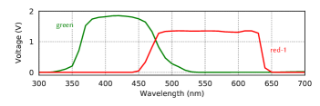
To assist the subsequent description of the attack, we use the Yealink SIP-T21P E2 telephone as a reoccurring example throughout the paper. For visually indicating the device’s state, this telephone makes use of two paired green and red SMD111Surface-mounted device (SMD) LEDs, and another individual SMD LED that emits red light. We refer to the paired diodes as green and red-1, and the individual one as red-2. These LEDs do not only differ in the emitted light’s wavelength, but also to which wavelength they react, when hit by a high-intensity light beam. As an example, Figure 2 (top) shows the sensitivity of the first red and the green diodes of the Yealink telephone to incoming light of different wavelength. A thorough characterization of a wide range of LEDs is provided in Sections 5.1 and 4.1 when discussing data infiltration and exfiltration in practice.
3.1. Attacker Model
For our attacker model, we assume that an initial compromise has
happened on the target device through the software supply-chain similar
to the incidents at SolarWinds (FireEye Threat Research, 2020) and
CodeCov (Engelberg, 2021). For example, a regular update of the
device’s firmware might unnoticeably add the necessary code for sending
and receiving data through a built-in LED.
While many office devices, such as desk telephones and printers, expose
a vast attack surface to the outside world, we assume adequate
isolation, that in further consequence, poses the necessity for bridging
the air gap.
Moreover, we assume that device characteristics, such as built-in LEDs
and circuit details, are known to the attacker. This, however, is
information that can be derived from identically constructed devices and
device drivers.
Finally, for the attack to succeed, a direct line of sight is necessary
to observe and actuate the LED. Note, that for reading and writing the
general-purpose IO (GPIO) interface usually system privileges are
required.
The adversary, however, neither needs physical access to the
device, nor requires the owner of the hardware to accidentally or
intentionally interact with the device. Moreover, we do not assume any
upfront hardware modifications of the device.
3.2. Infiltrating Data (➊)
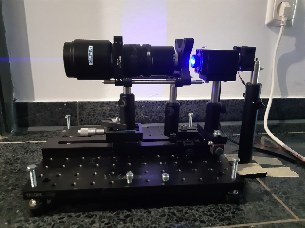
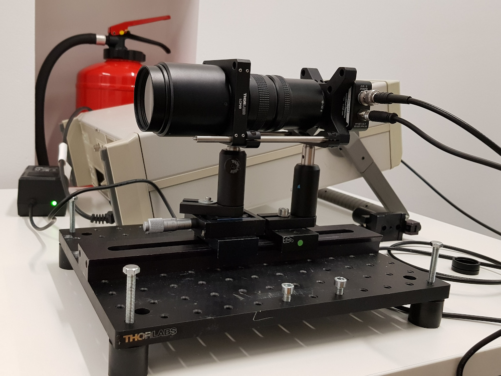
In contrast to the targeted device, the adversary is entirely free to choose the hardware necessary to establish a stable communication on the attacker’s end of the covert channel. While there are virtually no upper limits with respect to expense and size of the equipment, we implement the attack with mobile consumer components that are easily available and use household power. Our setup is shown in Figure 3.
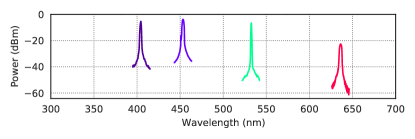
The wavelength of the laser beam is crucial for the success of the attack and needs to match the absorption range of the targeted LED. In the bottom part of Figure 2, we show the wavelength of four different lasers that emit blue/purple (two spikes to the left), green (middle spike) and red light (right most spike). This clearly shows that not all lasers can be used for inducing current into any diode. While the blue and purple lasers work well for the green, but not for the red LED of the Yealink telephone, for the green laser it is the other way around. Interestingly, the red laser does merely scratch the range of the red diode and is also far off the green one.
The four laser modules vary greatly in power but all are commercially available without restrictions in a range from –. Regular laser modules with less than are considered class –R and are available across rather broad light spectra in the range of –. More powerful devices emit up to and fall into class B. In common usage, such lasers are only available for fixed wavelengths, such as (purple), (green) and (red). Engraving lasers, finally, reach multiple Watts of energy and fall into class . These lasers typically use a wavelength of ~.
The distance that can be bridged using such lasers depends on the ability to focus the laser beam and the resulting optical power raised at the LED. The better the used telescope, the larger the distance. As part of our evaluation on data infiltration in practice, we provide measurements for the exact optical power of different lasers considered in our experiments and describe the used optics that are necessary in Section 4.2.
3.3. Exfiltrating Data (➋)
In contrast to producing light beams with high precision, the requirements at the attacker’s end for recording light signals sent out by the target device are less specialized. In the most simple case, a modern smartphone with a consumer high-speed camera, such as the iPhone since version 6 (Apple, 2020), is sufficient. These cameras capture light at and thus enable a moderate transmission rate. Furthermore, the bridgeable distance is constraint by the sensitivity of the camera. Both aspects can be improved upon by using specialized optics, such as a telescope similar to the one used to focus the laser beam, and a dedicated light sensor, such as a photodetector (PD). In Sections 5.2 and 5.3, we evaluate both scenarios in practice.
Conventional photodetectors have a response time of a few nanoseconds only and a broad spectral response. However, they are limited in sensitivity and have a small active area, which makes their use for capturing light signals over large distances difficult (see Guri et al., 2017c, 2019). For measuring very small amounts of light, we thus make use of so-called avalanche photodetectors (APD). These detectors create a strong electric field to increase the sensitivity to incoming light. When a photon hits the sensor, this electric field accelerates the electrons leading to the production of secondary electrons through impact ionization. The resulting avalanche of electrons produces a gain factor in the hundreds. This amplification limits the usable bandwidth of the detector to . Still, this rate significantly surpasses high-speed cameras and enables us to outperform existing covert channels. As part of our evaluation on data exfiltration in practice, in Section 5.3.1, we characterize the sensitivity of APDs in more detail.
[mode=buildmissing, height=30mm]figures/tex/mr3020_schematic
[mode=buildmissing, height=30mm]figures/tex/wr1043nd_schematic
[mode=buildmissing, height=30mm]figures/tex/t21p_schematic
3.4. Attackable Devices
A few prerequisites need to hold on a hardware level, such that a device can be targeted using our attack. For detecting laser pulses an already built-in LED needs to be connected to and directly driven by the processor via a GPIO interface. Whether the LED is configured as active high or active low is not relevant, as long as it is not permanently carrying electric current (constantly glowing). Also, while the presence of pull-up/down resistors or any additionally used series-connected resistors affect the GPIO levels, they do not impede the attack. To determined the prevalence of devices with built-in LEDs usable for the LaserShark attack, we have analyzed the device tree specifications of the Linux kernel. () of investigated boards use LEDs at the GPIO interface, from which the majority () is operated in an active high configuration.
Some devices additionally use a capacitor between GPIO and ground, in order to filter the signal. This does not impede the communications channel either, but requires alternative sampling strategies at the target device when receiving data to be infiltrated. In the following experiments, presented in Sections 4 and 5, we thus consider three representative office devices: a) TP-Link TL-MR3020 mobile router, b) TP-Link TL-WR1043ND office router, and c) Yealink SIP-T21P E2 telephone. Each of these devices uses a different circuit for connecting their built-in LEDs to the general-purpose I/O interface of the CPU. Further details on these devices are listed in Table 3.
Figure 4 shows simplified schematics for all three. For both routers the processor and LEDs are directly linked via a series-connected resistor, while an additional capacitor is used in Yealink’s device to avoid interference. The additional resistor R4 of the TP-Link TL-MR3020 needs to be present in case there is no internal pull-down. The CPU of the TP-Link TL-WR1043ND, in turn, does implement a pull-down resistor internally and, thus, can be used directly. The design of the different circuits requires the use of two different sampling strategies that we detail in the following.
3.4.1. Immediate sampling
In the case of a series-connected resistor between LED and the processor’s GPIO, the firmware’s GPIO API can be directly used to get the current state of the pin. Toggling the state by pointing the laser at the LED requires injecting a sufficient amount of energy to the circuit, such that the voltage at the pull-down resistor reaches the minimal switching threshold. For instance, for the TP-Link TL-MR3020 an induced current of is needed to reach a voltage of due to the built-in resistor.
3.4.2. Delayed sampling
Immediate sampling is not possible if there is an additional capacitor between GPIO and ground (irrespective of being pulled up or down), because the injected energy is first stored in the capacitor without toggling the GPIO. Therefore, it is necessary to charge the capacitor until its voltage is high enough to retrieve a sample by reading the state of the GPIO as shown in Figure 5. The sampling method consists of three phases: First, the capacitor is charged up to the desired voltage. Second, the logical GPIO value is retrieved. After that it is necessary to unload the capacitor in the third phase. This process takes a constant amount of time and, thus, leads to a lower sampling rate than the theoretically possible bandwidth of the LED.
Technically, the time required to charge the unit is defined by its electrical capacitance and is computed as follows: , where represents the induced current and the voltage level at the capacitor in the target device. An exemplary capacitor with , an applied voltage of , and an laser-induced current of thus requires to charge, meaning, the communication protocol is delayed by that duration. The advantage of such delayed sampling, however, is that less energy has to be injected to the LED, as it is possible to wait until the capacitor is charged. For the same reason, transmission is more robust in this setting as charging may be subject to discontinuity as caused by vibrations (cf. Section 4.2) without impeding the attack.
[mode=buildmissing,width=1.0]figures/tex/ex_trans
3.5. Communication Protocol
Infiltrating data into devices without real-time capable processors requires the use of an easy and robust modulation technique. For our attack, we hence use a variant of pulse-width modulation (PWM) (see Kennedy and Davis, 2005): Transmitting a zero bit corresponds to a short pulse while transmitting a one bit is achieved by a long pulse as indicated in Figure 5 (top). This scheme is owed to the sampling strategy described above. A high value indicates that the laser is active, while a low value indicates that it is off. The slots where the laser is not active are used to tell individual bits apart. The achievable data rate consequently depends on the ratio of zero and one bits. For subsequent experiments, we consider the worst-case (only 1-pulses are sent) to report a lower bound of the data rate.
For exfiltrating data, however, we are not restricted to a particular sampling strategy as the attacker may choose his/her hardware at will at the receiving end. On the office device, we thus use classical on-off-keying (OOK) for sending data, that is, a high value encodes a one bit, while a low value represents a zero bit. The duration of transmitting each is identical . Separating bits as described above is not necessary: . To further increase the data rate other encodings, such as amplitude-shift keying (ASK) (see Kennedy and Davis, 2005, Chp. 3) or (binary) frequency-shift keying (FSK, B-FSK) (see Kennedy and Davis, 2005, Chp. 5) are possible. Exploring this, however, is left to future work.
4. Infiltrating Data
After outlining the attack setting and describing the underlying channel for covert communication, we now demonstrate the attack in practice and begin with infiltrating data into remote devices. By directing a high-intensity laser beam onto a office device’s LED it is possible to induce a measurable current that allows to establish data communication. The experimental setup is detailed in Figure 6.

In particular, in Section 4.1, we systematically evaluate the light absorption characteristics of different LEDs that can be used as a receiver and thus contrary to its intended purpose. In Section 4.2, we then describe the laser modules necessary to actuate the LEDs and address peculiarities of the used hardware, the necessary optics, and issues with vibrations. Based on these characterizations, we conduct two experiments in Section 4.3. We first establish an empirical upper limit for infiltrating data based on the described target devices over a rather short distance, before we conduct measurements in an realistic setting with distances of up to .
4.1. LEDs as Receiver
For the attack to succeed, the wavelength of the used laser needs to align with the absorption spectrum of the LEDs to establish a reliable communication channel for infiltrating data. We thus inspect the light absorption of common LEDs, that enables us to put the measurements of the device-specific LEDs as presented in Figure 2 for the Yealink telephone into perspective. Details and specifications of the specific LEDs are provided in Appendix A.
In principle, any reversely biased LED can act as a poorly designed photodetector for which the flow of electricity is caused in the entire active layer and the junction itself. Therefore, the absorption spectrum of an LED equals the spectrum of the emitted wavelength. Hence, we begin with determining the absorption spectra of the diodes in question. This is commonly done using a white-light source (e.g., a LOT Quantum Design, LSH 302) and a monochromator (e.g., MC Pherson 2035) to continuously adjust the wavelength. To better focus the light on the LED, additional optics is used. Figure 7 shows the absorption curves for seven diodes, for which we measure the induced voltage in dependence on the illuminated light for different wavelengths with a resolution of .
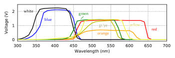
Usually, the absorption curve is shifted towards the lower end of the emitted spectra of wavelengths, as the LED is not able to detect photons of lower energy than its band gap (Stepniak et al., 2015). This is in line with our measurements, where the absorption of most diodes ranges broadly around the original color. Interestingly, this is not the case for the green SMD LED that the Yealink telephone uses (cf. Figure 2 top), where the absorption spectrum does not fit the emitting color at all, but leans towards white and blue color. Here, apparently, a white LED with a green colored cover has been built-in rather than a diode that actually emits green light. Of course, the diode may still be used for establishing a covert channel, but needs to be illuminated with a blue laser instead.
4.2. Laser Modules
The wavelength of the used laser beam is crucial for establishing a communication channel with a particular LED. To provide further insight into these relations, we determine the emission wavelengths and laser spectra of different laser modules in Section 4.2.1. Next to a matching (and powerful) laser, it is crucial for a successful attack to precisely focus the laser beam onto the targeted LED. In Section 4.2.2, we present the optical equipment used in our experiment and discuss how to handle vibrations to stabilize the laser beam.
4.2.1. Laser spectra
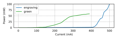
We measure the light of four different lasers using the free space input of an optical spectrum analyzer (Anritsu MS9701C) within a span of and a resolution of . The corresponding wavelengths are shown in the bottom part of Figure 2. As an example, to actuate the LEDs the Yealink telephone uses, the peak in optical power needs to reside in the absorption range of the diodes (top part of the figure). For bridging large distances, in turn, the optical power of the laser is crucial. In Figure 8, we characterize the green class 3B laser pointer and the purple/blue class 4 engraving laser out of the four laser modules mentioned above. For both, we measure the optical output power in dependence of the driving current. While the green laser pointer reaches an output of up to for the maximum current, much higher power is reached with the engraving laser. In order to avoid damage of the optical sensor the measurement has been limited to . According to the specification, the laser may achieve up to .
Moreover, to establish a communication protocol and transmit data, the laser is directly modulated, that is, the optical power of the laser is changed by varying the input current. It is important to note, that direct modulation also changes the output wavelength, which may cause signal loss at the edge of the absorption curve. Moreover, the modulation bandwidth of lasers crucially depends on the speed of the driver controlling the current. While integrated driver circuits for off-the-shelf laser pointers are limited to a few in speed, much higher bandwidths can be achieved with external current controllers. In general, a directly modulated laser module can reach bandwidths of up to (see Tadokoro et al., 2011).
Choice of laser module
In order to transmit the highest possible optical power over a long distance, subsequently, we make use of the strong class engraving laser, which has been purchased for merely on Ebay. To guard against any damage in the surroundings, we operate the laser module in a strictly marked out area using protective gear. The laser is driven by a separate current source (ILX Lightwave LDC3744C) that provides stable output with redundant current limiters. In this setting the laser current may reach up to and a compliance voltage of . We run the driver in constant current mode with external modulation such that the laser is switched on and off during modulation. The modulation signal itself is provided by an external controller.
4.2.2. Stabilizing laser beams across distance
The mentioned class 4 engraving laser comes with a small lens applied, such that the light beam diverges after a few meters. To counteract this, we use a telescope at the attacker’s side to focus the beam in distance. We use the Navitar Zoom 7000 telescope, which is a close-focusing macro video lens with a working distance from to (theoretically) infinity and is parfocal over the entire zoom range. However, in practice the beam of course shows some broadening over particular long distances above . With a price of the used telescope is on the lower end of the scale for professional optical equipment. Higher investments for better optics likely enable to extend the practical parfocal range significantly.
To overcome long distances it additionally is crucial to handle vibrations and stabilize the laser beam. With increasing distances, small vibrations lead to significant movement of the light spot. Minor movements of the building, for instance due to outside traffic, people, and elevators, may thus impede the attack, although unnoticeable as a person. To stabilize the setup, we mount the laser and the telescope on an optical plate with shock absorbing feet (Thorlabs AV4) made out of Sorbothane, a synthetic viscoelastic urethane polymer. For the given load, the absorption efficiency is – for frequencies above , which is sufficient for our experiments. To further compensate for vibrations one may also use fast steering, Piezo-activated mirrorsthat counteract movements in (near) real-time. Another significant source of distortions are movable parts of the sending equipment itself, such as fans. For our experiments, we hence detach the fan from the laser’s heat sink.
Once appropriate measures against vibrations have been established, the focal point of the telescope is adjusted on the target—the device’s LED—for the respective distance and applied with ultra-fine adjustment screws.
| Distance | Target Circuit | Laser | At the Target | Configuration | Data rate | ||||
| Resistor | Capacitor | Input Current | Optical Power | Current | |||||
| ● | |||||||||
| ● | |||||||||
| ● | |||||||||
| ● | |||||||||
| ● | |||||||||
| ● | – | – | – | ✗ | |||||
| ● | |||||||||
| ● | |||||||||
| Target device | Processor | Laser | LED | GPIO | Data rate | |||||
| TP-Link TL-MR3020 | Atheros AR-9331 | () | green | green | 0 | (WiFi LED) | ||||
| TP-Link TL-WR1043ND | Atheros AR-9132 | () | violet | green | 5 | (QSS LED) | ||||
| Raspberry Pi | BCM2837B0 | ( ) | violet | green222 | 26 | (Pin Header) | ||||
| Yealink SIP-T21P E2 | DSPG DVF-9918 | () | violet | green | 112 | (green/red button) | ||||
| Raspberry Pi | BCM2837B0 | ( ) | violet | green222 | 26 | (Pin Header) | ||||
| (with capacitor) | ||||||||||
| 222 Using the LEDs of the Yealink SIP-T21P E2 telephone. | ||||||||||
4.3. Data rate
To assess the achievable data rate of our attack, we measure transmission in two different settings: We first experiment in a laboratory setting to optimize our setup over a short distance and second, in a realistic setting across long distances to demonstrate the feasibility of the attack in practice.
4.3.1. Short-distance transmission
In the first experiment, we measure the transmission per target device over a distance of . This is too short for a practical instantiation of the attack, but enables us to optimize our setup for subsequent long-distance transmissions. Moreover, by narrowing down the external influence, we are able to establish an empirical upper limit that may be achieved with the particular hardware of the attacked devices. The used components (LEDs, GPIOs specifications, processor, etc.) and the achievable data rate are summarized in Table 3. The specified times indicate the configuration for the pulse-width modulation (PWM). In addition to the three target devices, we also include a Raspberry Pi as a reference device.
A few things stand out: First, for the TP-Link TL-MR3020, we make use of a green laser rather than the more powerful engraving laser. This was necessary, as the device’s LED emits green light, in contrast to the others that emit white light but carry a green cap. The green laser, however, is slower than the purple one such that we yield a lower data rate. Second, both devices are slower than the Raspberry Pi, which underlines a certain dependency of the data rate on the CPU speed and, thus, the possible sampling rates. Third, the Yealink telephone is significantly slower than all the above. As mentioned earlier, for this device an additional capacitor is built-in such that the sampling rate is limited by the charge time of the capacitor. Equipping the Raspberry Pi with the very same capacitor and the same LEDs enables twice the data rate, due to the higher sampling rate.
To expand on these results and stretch the limits of the attack, subsequently, we focus on the LEDs of the Yealink telephone in combination with the Raspberry Pi that is equipped with a CPU.
4.3.2. Long-distance transmission
For our long-distance experiment, we consider both predominate circuit types that either use a series-connected resistor, as used by the TP-Link TL-WR1043ND router, or an additional capacitor, as it is the case for the Yealink SIP-T21P E2 telephone. The setup remains as depicted in Figure 6.
We transmit data packets of in size and record them on the other end. The recorded data is then compared with the transmitted one to verify error-free communication. These transmissions are evaluated for different circuits and with increasing distances for , , , , and . Table 2 summarizes the results. All measurements have been conducted indoors, due to safety reasons.
Over consecutive repetitions of each experiment, data transmission succeeds without a single bit error ( ). For circuits with a series-connected resistor (TP-Link TL-WR1043ND and TP-Link TL-MR3020 routers), we achieve a remarkable data rate of across . Beyond this, the rate declines to for and transmission comes to a halt at . Similarly to the short-distance measurements before, we however also see a significant difference in the achievable data rate for targets that use a capacitor, which are slower by a factor of . Nevertheless, even are sufficient to establish a command-and-control channel to air-gapped systems and enable orchestrating different malicious activities. Moreover, the capacitor enable to operate on lower levels of induced current at the target and, thus, allows to overcome larger distances.
To better highlight these relations, we also measure the optical power that reaches the target with a Thorlabs PME320E optical power meter and the corresponding Thorlabs S120VC power sensor. To match the size of an SMD LED and its effective area, we cover large portions of the sensor such that only about remains sensitive. Even with a laser input current of the induced current only reaches in distance, while for shorter ranges at least are reached. In this setting, is a tipping point, where a reliable, error-free communication channel can still be established for circuits with series-connected resistors. For large distances, however, vibrations are the limiting factor that impair the attack. This may be counteracted using fast steering mirrors to level the laser beam as described in Section 4.2.2. Targets that incorporate circuits with capacitors can even be communicated with across . This is equivalent to the width of a highway with eight lanes including median and shoulders on each side. Charging the capacitor is largely unaffected by vibration, but slightly slowed down. This, however, is easily compensated by the communication protocol (cf. Section 3.5).
Summary. We demonstrate data transmission to built-in LEDs with data rates of and up to if no capacitor is used in the circuit. Consequently, infiltrating data into air-gapped devices, such as the two TP-Link routers, becomes possible at speeds comparable to regular modems.
5. Exfiltrating Data
We continue to show how data can be exfiltrated from the targeted devices. By flashing built-in LEDs, it is possible to establish arbitrary communication protocols and transmit data. Reaching realistic attack distances, however, requires efficient optical equipment. In contrast to prior work, we show that it is perfectly feasible to overcome large distances and achieve high data rates without modifications of the targeted hardware.
We begin with a systematic evaluation of the sending capabilities of LEDs in Section 5.1. Subsequently, in Sections 5.2 and 5.3, we demonstrate data exfiltration in two different scenarios, where we use a) consumer high-speed cameras as available in modern smartphones, and b) more advanced, but equally affordable avalanche photodetectors. With the latter it is possible to push the limits of the communication and significantly outperform existing covert channels that use LEDs.
5.1. LEDs as Sender
For data exfiltration the emitted light has to be powerful enough to be observable by the adversary. Subsequently, we thus determine the characteristics of different LEDs and measure their bandwidth, that is, the theoretically achievable data rate, as well as the optical power of the emitted light in Sections 5.1.1 and 5.1.2, respectively. Details and specifications of the LEDs are provided in Appendix A.
5.1.1. Bandwidth
For evaluating the theoretically achievable data rates that can be transmitted with consumer LEDs, we proceed to measure the modulation bandwidth. The setup is as follows: The LEDs are actuated by a radio frequency generator (RFG) that generates a sweep frequency from up to with an effective output voltage of . The light emitted by the LED is then measured with a photodetector (PD), a Thorlabs PDA8A, in a distance of . This silicon-based detector exhibits a spectral response of – on an active area of . The wavelengths of the previously characterized LEDs thus are entirely in range. The actual response of the diodes is finally recorded with an electrical spectrum analyzer (ESA) in maximum hold mode.
| LED | Bandwidth | Optical Power | |||
|---|---|---|---|---|---|
| [3 dB] | Bias | Sine | Burst | ||
| Exemplary selection | yellow | ||||
| gr/ye | |||||
| green | |||||
| orange | |||||
| red | |||||
| blue | |||||
| white | |||||
| Yealink | green | ||||
| red-1 | |||||
| red-2 | |||||
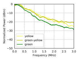
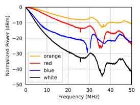
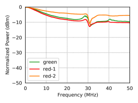
Figure 9 shows the frequency response for a) low-bandwidth and b) high-bandwidth conventional SMD LEDs, and c) for those used by the Yealink telephone. The conventional SMD diodes show widely different behavior concerning the possible modulation bandwidth, which is founded in the used materials and construction scheme of the devices. Usually, AlGaInP and InGaN are used in commercially available LEDs for red, amber and yellow as well as green and blue colors, respectively (Kasap, 2013; Schubert, 2018). Moreover, InGaN diodes typically are constructed as Multiple Quantum Well (MQW) structures, whereas AlGaInP devices are build as Double Heterojunctions (DH). Due to the different materials and layer structures, there are diverse charge carrier lifetimes, which in turn results in the different modulation bandwidths (Pei et al., 2013).
The maximum theoretical modulation bandwidth of LEDs is limited to (Chen et al., 1999; Koudelka and Woodall, 2011). In our experiments, the red and orange LEDs can reach data rates of to for on-off modulation. The LEDs from the Yealink telephone show even higher modulation bandwidths with rates of up to . An overview of the exact bandwidth characteristics is given in Table 4. Values are specified as the full width at half maximum (FWHM) bandwidth, that is, the frequency where the transmitted power has decreased by the half or .
5.1.2. Optical power
Finally, we measure the maximally emitted optical power for each LED to assess how well consumer diodes are visible in distance. To this end, we replace the photodetector with an optical power meter (Thorlabs PME320E) and a power sensor (Thorlabs S120VC), and measure the emitted power in three different settings: First, we determine the maximum bias voltage that may be applied. Second, we modulate a sine wave with a frequency of with a voltage of . Finally, we apply a burst of large data blocks at a rate of and repeat it with , which allows us to estimate the power for data transmission. The results are shown in Table 4.
In particular, the blue and white LEDs show the highest output powers under the given conditions. However, the average output power is decreased if modulation is applied, as we turn off the LED for transmitting a digital zero. This, of course, needs to be considered for determining the maximum distance and data rate in subsequent experiemnts. Generally speaking, the higher the output power the better we are able to bridge large distances. Much of the restrictions imposed at this point, however, can be overcome by hardware for effectively capturing light as detailed in Section 5.3.
5.2. Exfiltration using high-speed cameras
Modern smartphones often have the ability to capture slow-motion videos. This boils down to an increased frame rate of the recorded video, that is, high-speed camera functionality. These cameras are very sensitive to small and dark light sources, such that they are perfectly suited for our attack.
In the first experiment, we thus use an iPhone 11 that comes with a 1080p camera to exfiltrate data from three target devices: TP-Link TL-WR1043ND, TP-Link TL-MR3020, and the Yealink SIP-T21P E2 telephone. The procedure is as easy as capturing a video of the target device while it is transmitting. Analyzing the video stream, in turn, is done offline on more performant hardware. In a more specialized setting, as for instance demonstrated in Section 5.3, this can however be equally conducted online. Moreover, here the attacker is not limited to a specific sampling strategy, such that we can use on-off-keying (OOK) for modulation (cf. Section 3.5). Due to the camera’s limited frame rate and the Nyquist–Shannon sampling theorem (see Kennedy and Davis, 2005) the achievable data rate is limited to . To empirically verify this, we transmit three randomly generated data chunks of in size using each target device, while filming it with the iPhone. The size of transmitted data is reduced in comparison to the previous experiment as the iPhone’s internal storage quickly runs full given the large size of the recorded video.
| Target device | Distance | Data rate |
|---|---|---|
| TP-Link TL-MR3020 | 2 – 40 | |
| TP-Link TL-WR1043ND | 2 – 40 | |
| Yealink SIP-T21P E2 | 2 – 40 |
We conduct two different sets of experiments, that are summarized in Table 5. At first, we measure transmission on a short range of indoors, and proceed to long-range measurements across outdoors (the maximum distance possible at our testing grounds). In line with the “consumer setting” of using non-specialized hardware, for the second experiment, we use regular binoculars (Minox BL 10x44 HD) to zoom in on the LEDs of the target devices. In all cases, we nearly yield the theoretical maximum. In contrast to transmitting data using laser beams, here a distance of does not affect the data rate. Larger distances could not be investigated due to the boundaries of our testing grounds. However, reception is possible as long as at least a single pixel that represents the LED is visible.
5.3. Exfiltration using photodetectors
While high-speed cameras are very sensitive to light, they have a clear limit imposed by their frame rate. Photodetectors, in turn, allow to improve upon this limitation at the expense of sensitivity. To yield the highest possible signal-to-noise ratio at rather low optical input power levels, we use an avalanche photodetector (APD) that we characterized in Section 5.3.1. To compensate for large distances and improve reception, an attacker may use more efficient optical equipment. In subsequent experiments, we thus employ the telescope, that has also been used for focusing the laser beam on the target (the Navitar Zoom 7000) rather than ordinary binoculars. In Section 5.3.2, we again direct our attention to the Yealink telephone with its green and red SMD LEDs to inspect a) the raw observability in distance, and b) the data rate in a realistic setting.
5.3.1. Sensitivity of Photodetectors
For recording the data send out by an LED of a compromised device over large distances, we require highly sensitive and fast hardware to capture light. Photodetectors are made from element semiconductors such as silicon, germanium, or compound semiconductors such as indium gallium arsenide. For visible light (nm–) mainly detectors made of silicon (–) and germanium (–) are used. Due to the larger band gap of silicon it is possible to also achieve comparable low noise. Conventional photodetectors, however, have limited sensitivity and no internal gain, such that additional transimpedance amplifiers are necessary for operation, which again reduces the overall signal-to-noise ratio. For measuring the smallest amounts of light so-called avalanche photodetectors (APDs) may be used, which produce a gain factor in the hundreds using a photoelectric effect based on impact ionization.
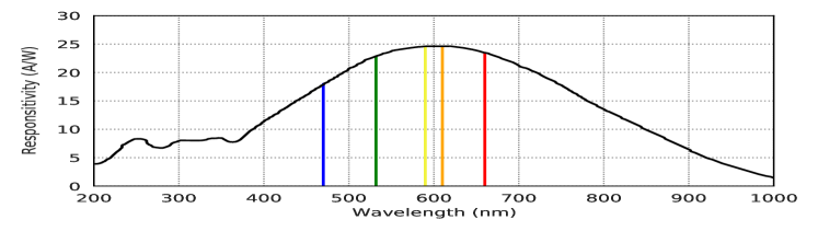
To characterize the receiving capabilities of an attacker, we hence evaluate the sensitivity of a silicon-based APD. In particular, we make use of the Thorlabs APD440A2, which promises a low signal-to-noise ratio at rather low optical input power levels. It operates on a range from – with a maximum responsivity of at a noise-equivalent power of . As we attempt to measure a wide-range of light-emitting diodes with different wavelengths, we break down the responsivity of the APD by color in Figure 10. Especially the green and red LEDs exhibit almost optimal output levels, making the avalanche photodetector a well-suited receiver for exfiltrating data from consumer devices. For subsequent experiments, we use the photodetector with a gain or multiplication factor of . More information on this configuration and the exact frequency response is provided in Appendix B.
5.3.2. Data rate
Finally, we measure the data rate when exfiltrating data using LEDs. For this, we implement the experimental setup depicted in Figure 11 and conduct two different measurements. First, we gauge the electrical response of the photodetector to LEDs in distance to explore the limits of the communication channel. For this, we modulate the LEDs using an arbitrary waveform generator (AWG) such that the diodes emit a burst of rectangular signals. Second, we replace the AWG with the malicious implant at the target and transmit large data chunks to determine the bit error rate of the communication channel.

| LED | ||||||
|---|---|---|---|---|---|---|
| green | ✗ | |||||
| red-1 | ✗ | ✗ | ||||
| red-2 | ✗ | ✗ | ✗ | ✗ |
| LED | ||||||
|---|---|---|---|---|---|---|
| green | ||||||
| red-1 | ||||||
| red-2 | ✗ | ✗ | ✗ | ✗ |
We begin by modulating bursts of rectangular signals at a data rate of and repeat this at with an effective output voltage of . The signals captured by the APD are recorded with a real time oscilloscope resulting in high/low voltage patterns that can be interpreted as the corresponding data pattern. The measured voltage levels are reported in Table 6. We characterize the measured response a) with and b) without an additional series-connected resistor of as used by the Yealink telephone. For both measurements, it is clearly visible that the observed levels and thus the response decays with increasing distance. With the resistor in place, we are able to bridge a distance of with the green LED and with the first red LED (red-1). The second red diode (red-2) is less bright and thus reaches less far, which matches the intuition one has of the setting. Subsequently, we thus use the telephone’s green LED for our experiments on the data rate in practice.
We transmit large data chunks at an output voltage of , digitize the measured high/low levels, and calculate the bit error rate (BER) between sent and received bit streams. The results are presented in Table 7. For up to and data rates of , transmission is possible with minimal bit errors (). Due to the limited bandwidth of the APD, however, the measured bit error increases significantly for data rates of and distances above , such that transmission abruptly becomes impossible. With a more sensitive detector and improved optics, however, this can likely be enhanced even further.
Moreover, one may even modulate the background light of the telephone’s display to transmit data. In comparison to the rather small LEDs, the LCD display constitutes a large and bright light source that promises a better reception at the photodetector. We extend on this idea in Appendix C.
| Distance | Data rate | |||
| ✗ | ||||
| ✗ | ||||
| ✗ | ✗ | ✗ | ✗ | |
Summary. We demonstrate that LEDs used in office devices can be used for high-speed exfiltration of data. We achieve a throughput of up to a distance of . This data rate enables to transfer megabytes of data within minutes and thus poses a serious threat to air-gapped environments.
6. Conclusion
An air-gapped system is unreachable from the outside by definition. The research community, however, has shown that this is not necessarily true, and has demonstrated multiple ways of bridging the gap in the past. While these methods feature various very creative covert channels, their practical utility often remains questionable due to low data rates, short distances, or only unidirectional communication. We are the first to demonstrate the exfiltration of data at over and allow for infiltrating data to an unmodified device in distance at . With this, we show that covert channels are not bound to obscure and rare settings, but are a real threat in practice.
Network operators of high-security facilities and industries that are at risk of cooperate espionage must not settle for merely air-gapping a system, but also need to prevent targeted attacks that make use of a physical component—for instance, using optical channels that require a direct line of sight. Obvious countermeasures for this particular attack are optically opaque rooms. However, as demonstrated by related approaches, this threat extends to other variations using electromagnetic, acoustic, or power-dependent aspects.
Acknowledgements.
The authors gratefully acknowledge funding from the German Federal Ministry of Education and Research (BMBF) under the project XXX (FKZ 00XXX0000Y).References
- NSA [2008] NSA ANT catalog. Technical report, US National Security Agency (NSA), 2008.
- Apple [2020] Apple. Phone 6 – technical specifications. https://support.apple.com/kb/sp705?locale=en_US, 2020. Accessed May. 2021.
- Baker and Chalmers [2020] L. Baker and J. Chalmers. As britain bans huawei, u.s. pressure mounts on europe to follow suit. https://www.reuters.com/article/us-britain-huawei-europe/as-britain-bans-huawei-u-s-pressure-mounts-on-europe-to-follow-suit-idUSKCN24F1XG, 2020.
- Basu et al. [2019] K. Basu, S. M. Saeed, C. Pilato, M. Ashraf, M. T. Nabeel, K. Chakrabarty, and R. Karri. CAD-Base: An attack vector into the electronics supply chain. ACM Transactions on Design Automation of Electronic Systems (TODAES), (38), 2019.
- Chan [2006] V. W. S. Chan. Free-space optical communications. J. Lightwave Technol., 24(12):4750–4762, Dec 2006.
- Chen et al. [1999] C. Chen, M. Hargis, J. Woodall, M. Melloch, J. Reynolds, E. Yablonovitch, and W. Wang. GHz bandwidth GaAs light-emitting diodes. Applied physics letters, 74(21):3140–3142, 1999.
- Deshotels [2014] Deshotels. Inaudible sound as a covert channel in mobile devices. In Proc. of the USENIX Workshop on Offensive Technologies (WOOT), 2014.
- Engelberg [2021] J. Engelberg. Bash uploader security update. https://about.codecov.io/security-update/, 2021. Accessed May. 2021.
- FireEye Threat Research [2020] FireEye Threat Research. Highly evasive attacker leverages SolarWinds supply chain to compromise multiple global victims with SUNBURST backdoor. https://www.fireeye.com/blog/threat-research/2020/12/evasive-attacker-leverages-solarwinds-supply-chain-compromises-with-sunburst-backdoor.html, 2020. Accessed May. 2021.
- Genkin et al. [2019] D. Genkin, M. Pattani, R. Schuster, and E. Tromer. Synesthesia: Detecting screen content via remote acoustic side channels. In Proc. of the IEEE Symposium on Security and Privacy, pages 853–869, 2019.
- Guri [2019] M. Guri. HOTSPOT: Crossing the air-gap between isolated pcs and nearby smartphones using temperature. In Proc. of the European Intelligence and Security Informatics Conference (EISIC), pages 94–100, 2019.
- Guri and Zadov [2019] M. Guri and B. Zadov. aIR-Jumper: Covert air-gap exfiltration/infiltration via security cameras & infrared (IR). Computers & Security, 82:15–29, 2019.
- Guri et al. [2014] M. Guri, G. Kedma, A. Kachlon, and Y. Elovici. AirHopper: Bridging the air-gap between isolated networks and mobile phones using radio frequencies. In Proc. of the International Conference on Malicious and Unwanted Software: The Americas (MALWARE), pages 58–67, 2014.
- Guri et al. [2015a] M. Guri, A. Kachlon, O. Hasson, G. Kedma, Y. Mirsky, and Y. Elovici. GSMem: Data exfiltration from air-gapped computers over GSM frequencies. In Proc. of the USENIX Security Symposium, 2015a.
- Guri et al. [2015b] M. Guri, M. Monitz, Y. Mirski, and Y. Elovici. BitWhisper: Covert signaling channel between air-gapped computers using thermal manipulation. In Proc. of the IEEE Computer Security Foundations Symposium, 2015b.
- Guri et al. [2016] M. Guri, M. Monitz, and Y. Elovici. USBee: Air-gap covert-channel via electromagnetic emission from usb. In Proc. of the Annual Conference on Privacy, Security and Trust (PST), 2016.
- Guri et al. [2017a] M. Guri, M. Monitz, and Y. Elovici. Bridging the air gap between isolated networks and mobile phones in a practical cyber-attack. ACM Transactions on Intelligent Systems and Technology (TIST), 50(2), 2017a.
- Guri et al. [2017b] M. Guri, Y. A. Solewicz, A. Daidakulov, and Y. Elovici. Acoustic data exfiltration from speakerlessair-gapped computers via covert hard-drivenoise (‘DiskFiltration’). In Proc. of the European Symposium on Research in Computer Security (ESORICS), pages 98–115, 2017b.
- Guri et al. [2017c] M. Guri, B. Zadov, and Y. Elovici. Led-it-go: Leaking (a lot of) datafrom air-gapped computers via the (small)hard drive led. In Proc. of the Conference on Detection of Intrusions and Malware & Vulnerability Assessment (DIMVA), pages 161–184, 2017c.
- Guri et al. [2018a] M. Guri, Y. A. Solewicz, and Y. Elovici. MOSQUITO: Covert ultrasonic transmissions between two air-gapped computers using speaker-to-speaker communication. In Proc. of the IEEE Conference on Dependable and Secure Computing, 2018a.
- Guri et al. [2018b] M. Guri, B. Zadov, A. Daidakulov, and Y. Elovici. xLED: Covert data exfiltration from air-gapped networks via switch and router leds. In Proc. of the Annual Conference on Privacy, Security and Trust (PST), pages 1–12, 2018b.
- Guri et al. [2019] M. Guri, B. Zadov, D. Bykhovsky, and Y. Elovici. CTRL-ALT-LED: Leaking data from air-gappedcomputers via keyboard leds. In Proc. of IEEE Annual Computer Software and Applications Conference (COMPSAC), pages 801–810, 2019.
- Guri et al. [2020a] M. Guri, Y. A. Solewicz, and Y. Elovici. Speaker-to-speaker covert ultrasonic communication. Journal of Information Security and Applications (JISA), 51, 2020a.
- Guri et al. [2020b] M. Guri, Y. A. Solewicz, and Y. Elovici. Fansmitter: Acoustic data exfiltration from air-gapped computers via fans noise. Computers & Security, 91, 2020b.
- Guri et al. [2020c] M. Guri, B. Zadov, D. Bykhovsky, and Y. Elovici. PowerHammer: Exfiltrating data from air-gapped computers through power lines. IEEE Transactions on Information Forensics and Security (TIFS), 15:1879–1890, 2020c.
- Guri et al. [2020d] M. Guri, B. Zadov, and Y. Elovici. ODINI: Escaping sensitive data from faraday-caged, air-gapped computers via magnetic fields. IEEE Transactions on Information Forensics and Security (TIFS), 15:1190–1203, 2020d.
- Haas et al. [2016] H. Haas, L. Yin, Y. Wang, and C. Chen. What is lifi? Journal of Lightwave Technology, 34(6):1533–1544, 2016.
- Jovicic et al. [2013] A. Jovicic, J. Li, and T. Richardson. Visible light communication: opportunities, challenges and the path to market. IEEE Communications Magazine, 51(12):26–32, 2013.
- Kahn and Barry [1997] J. M. Kahn and J. R. Barry. Wireless infrared communications. Proceedings of the IEEE, 85(2):265–298, 1997.
- Kasap [2013] S. Kasap. Optoelectronics & Photonics:Principles & Practices: International Edition. Pearson Education Limited, 2013. ISBN 9780273774181. URL https://books.google.de/books?id=Qp2pBwAAQBAJ.
- Kennedy and Davis [2005] G. Kennedy and B. Davis. Electronic Communication Systems. Tata McGraw-Hill, 4th edition, 2005.
- Komine and Nakagawa [2004] T. Komine and M. Nakagawa. Fundamental analysis for visible-light communication system using led lights. 21(4):100–107, 2004.
- Koudelka and Woodall [2011] R. D. Koudelka and J. M. Woodall. Light Emitting Devices with Increased Modulation Bandwidth. Yale University, 2011.
- Matheus et al. [2019] L. E. M. Matheus, A. B. Vieira, L. F. M. Vieira, M. A. M. Vieira, and O. Gnawali. Visible light communication: Concepts, applications and challenges. IEEE Communications Surveys Tutorials, 21(4):3204–3237, 2019.
- Pathak et al. [2015] P. H. Pathak, X. Feng, P. Hu, and P. Mohapatra. Visible light communication, networking, and sensing: A survey, potential and challenges. IEEE Communications Surveys Tutorials, 17(4):2047–2077, 2015.
- Pei et al. [2013] Y. Pei, S. Zhu, H. Yang, L. Zhao, X. Yi, J. J. Wang, J. Li, et al. Led modulation characteristics in a visible-light communication system. Optics and Photonics Journal, 3(2B):139–142, 2013.
- Schubert [2018] E. Schubert. Light-Emitting Diodes (3rd Edition). E. Fred Schubert, 2018. ISBN 9780986382666. URL https://books.google.de/books?id=GEFKDwAAQBAJ.
- Shackleford [2015] D. Shackleford. Combatting cyber risks in the supply chain. Technical report, SANS Institute, 2015.
- Stepniak et al. [2015] G. Stepniak, M. Kowalczyk, L. Maksymiuk, and J. Siuzdak. Transmission beyond 100 Mbit/s using LED both as a transmitter and receiver. IEEE Photonics Technology Letters, 27, 2015.
- Sugawara et al. [2020] T. Sugawara, B. Cyr, S. Rampazzi, D. Genkin, and K. Fu. Light Commands: Laser-based audio injection attacks on voice-controllable systems. In Proc. of the USENIX Security Symposium, 2020.
- Tadokoro et al. [2011] T. Tadokoro, W. Kobayashi, T. Fujisawa, T. Yamanaka, and F. Kano. High-speed modulation lasers for 100gbe applications. In Optical Fiber Communication Conference/National Fiber Optic Engineers Conference 2011, page OWD1. Optical Society of America, 2011.
- The White House [2020] The White House. Executive order on securing the united states bulk-power system. https://www.whitehouse.gov/presidential-actions/executive-order-securing-united-states-bulk-power-system/, 2020.
- Uysal and Nouri [2014] M. Uysal and H. Nouri. Optical wireless communications — an emerging technology. In 2014 16th International Conference on Transparent Optical Networks (ICTON), pages 1–7, 2014.
| Color | Type | Manufacturer | Part No. | Brightness | Angle of Radiation | Current | Voltage |
|---|---|---|---|---|---|---|---|
| Yellow | SMD-LED 0603 | Würth Elektronik | 150060YS75000 | mcd | |||
| Green/Yellow | SMD-LED 0603 | Broadcom | HSME-C191 | mcd | |||
| Green | SMD-LED 0603 | Kingbright | KPHCM-2012CGCK | mcd | |||
| Blue | SMD-LED 0603 | TRU Components | 1573646 | mcd | |||
| White | SMD-LED 0603 | TRU Components | 1573647 | mcd | |||
| Orange | SMD-LED 0603 | Kingbright | KP-1608SECK | mcd | |||
| Red | SMD-LED 0603 | Würth Elektronik | 150060RS75000 | mcd |
Appendix A Selection of LEDs
For evaluating the characteristics of light-emitting diodes and the suitability of these to be used for a covert channel, we have used a selection of SMD LEDs in Sections 4.1 and 5.1. To allow for easy reproducibility of our experiments, Table 8 list manufacturers, part numbers, and basic properties of these.
Appendix B Photodetector Gain
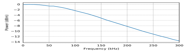
A photodetector’s gain or multiplication factor is dependent on the reverse bias voltage, that is used to create the electric field for triggering the avalanche effect, but also the temperature. While the multiplication factor increases and decreases with the reverse bias voltage, it is inversely proportional to the temperature, meaning, the gain increases at low temperatures, but decreases if the temperature rises. However, the amplification limits the FWHM bandwidth of the detector to , which in turn bounds the maximally transmittable data rate. For the experiments presented in Section 5.3, we use a gain factor of which exhibits the frequency response shown in Figure 12.
| Distance | Data rate | |||
|---|---|---|---|---|
| ✗ | ||||
| ✗ | ||||
| ✗ | ||||
| ✗ | ✗ | ✗ | ||
| ✗ | ✗ | ✗ | ✗ | |
Appendix C Transmitting Data with
LCD Displays
Similar to LEDs, the background light of an (LCD) display can be used to transmit data. The display constitutes a large and rather bright light source that promises a better reception at the APD. However, next to brightness itself, also the wavelength of light is crucial for the sensitivity of the (avalanche) photodetector. In case of the Yealink SIP-T21P E2, the background light mainly emits blue light, which is not covered well by the detector as shown in Figure 10. As the APD responds less to blue than green light, this also reflects in the distance that can be overcome.
Although the detector is not very well suited for the white/blue light of the telephone’s display, it still is possible to also exfiltrate data using the background light. As shown in Table 9, for a distance of up to , we achieve a data rate of without any bit error when modulated with traditional on-off keying. Even at a distance of transmission is possible with up to and a BER of . Beyond this, however, no noteworthy output and thus data rate can be measured.