Extending Reference Broadcast Infrastructure Synchronization Protocol in IEEE 802.11 as Enabler for the Industrial Internet of Things††thanks: This research was supported by the German Federal Ministry for Economic Affairs and Energy (BMWi) within the project FabOS under grant number 01MK20010C. The responsibility for this publication lies with the authors. This is a preprint of a work accepted but not yet published at the IEEE 4th International Conference on Industrial Cyber-Physical Systems (ICPS). Please cite as: M. Gundall, C.Huber, S. Melnyk, and H.D. Schotten: “Extending Reference Broadcast Infrastructure Synchronization Protocol in IEEE 802.11 as Enabler for the Industrial Internet of Things”. In: 2021 4th International Conference on Industrial Cyber-Physical Systems (ICPS), IEEE, 2021.
Abstract
Realizing the industrial Internet of Things, more and more mobile use cases will emerge in the industrial landscape, requiring both novel concepts and smooth integration into legacy deployments.
Since accurate time synchronization is particularly challenging for wireless devices, we propose a concept for simple but accurate synchronization in IEEE 802.11 wireless local area network that extends the Reference Broadcast Infrastructure Synchronization protocol, and a suitable integration of IEEE 802.1AS that is part of the IEEE time-sensitive networking standards. In addition, the concept is evaluated with a testbed using commercial off-the-shelf hardware and a realistic discrete automation demonstrator equipped mostly with industrial components. By using the aforementioned devices for wireless communications, this concept can be directly applied in existing industrial solutions, thus achieving the proposed results. It is shown that the achieved synchronicity is suitable for a wide range of mandatory mobile use cases, which are most important for a fully functional industrial Internet of Things.
Index Terms:
IEEE 802.11, Wi-Fi, IEEE 802.1AS, WLAN, TSN, Industrial Communication, Industrial Automation, Time Synchronization, Testbed, RBIS, IIoTI Introduction
The industrial Internet of Things (IIoT) describes the digitalization of all kinds of production assets that are called industrial cyber-physical systems (ICPSs). With their help, numerous novel use cases that are key enabler for a smart manufacturing, can be realized [1]. Furthermore, these use cases can be divided into optionally mobile and mandatory mobile, the former considering the use of wireless communication due to soft criteria such as cost savings, and the latter meaning use cases that cannot be covered by wired technologies due to the mobility of the devices. These use cases enhance the traditional applications in order to ensure the required flexibility of a smart manufacturing. One of the major differences is the requirement of wireless communications in order to allow the increasing number of mobile use cases. Table I sums up and classifies important use cases into classes as well as selected requirements, where we identified end-to-end (E2E) latency and synchronicity as particularly relevant. In addition, we listed the associated real-time classes for each use case class. Depending on the reference, these are listed from 1-3 or A-C. In the following, we use the latter.
| Use case class | Requirements | Real-time | |
| E2E latency | Synchronicity | class | |
| (I) | |||
| Remote control, monitoring | 10-100 ms | 1 s | 1 / A |
| (II) | |||
| Mobile robotics, process control | 1-10 ms | 1 ms | 2 / B |
| (III) | |||
| Closed loop motion control | 1 ms | 1 s | 3 / C |
Use cases that belong to use case class I, such as predictive maintenance and augmented reality (AR), belong to the lowest real-time class A and consequently have the lowest latency and synchronization requirements. Here, the time synchronization has to be better than 1 s. This means that a good time synchronization is not required for these use cases. Since E2E latencies of 10 – 100 ms are sufficient, the challenges for these use cases are mostly in the data rates that need to be supported due to the number of sensor nodes or video transmission and coverage of a large area.
Use cases belonging to the second class, which include mobile use cases, are the main target of the work in this paper. This class is particularly challenging because of the need for higher performance of time synchronization and E2E latency of wireless communications. Particularly demanding are collaborative use cases, where two and more mobile robots have to interact with each other. Here, a synchronicity of 1 ms is targeted.
Use case class III has the highest requirements for E2E latency and synchronicity and cannot be addressed by current wireless communication technologies. Here both, concepts for combining IEEE time-sensitive networking (TSN) and 5th generation wireless communication systems (5G) [4] as well as TSN and wireless local area network (WLAN) [5, 6] are discussed. Since the argument for an introduction of wireless communications in this use case class is mainly the potential of cost savings [2, 5, 7], we call these use cases optionally mobile. Thus, we will not address this use case class in our work.
Therefore, the following contributions can be found in this paper:
-
•
Concept for extending the Reference Broadcast Infrastructure Synchronization (RBIS) protocol in IEEE 802.11 in order to fulfill the synchronicity required by ICPSs and the IIoT.
-
•
Performance evaluation of the method based on a testbed and a discrete automation demonstrator.
Accordingly, the paper is structured as follows: Sec. II gives insights into related work on this topic, while an overview on RBIS protocol and IEEE 802.11 is given in Sec. III. Furthermore, details on the concept for the integration of IEEE 802.11 with IEEE 802.1AS using RBIS protocol are proposed in Sec. IV. This is followed by a performance evaluation based on a testbed consisting mainly of commercial off-the-shelf (COTS) communication hardware, and a realistic discrete automation demonstrator (Sec. V). Finally, the paper is concluded in Sec. VI.
II Related Work
Accurate time synchronization of wireless systems differs significantly from wired systems [8]. This can be caused by changes of the propagation path of the communication signal during operation due to movement or changed channel conditions. Therefore, the time for message propagation between devices is not constant, but can vary greatly, in contrast to cables. Therefore, [9, 2] summarize concepts for time synchronization of wireless systems, the latter focusing on IEEE 802.11 WLAN. In addition, a concept of an improved time synchronization by estimating the distance to the access point (AP) using the station’s receive power [9] was proposed. Furthermore, a concept for integrating Precision Time Protocol (PTP) and IEEE 802.11 using the RBIS protocol was presented [10] and evaluated [11]. This method takes advantage of the broadcast nature of the wireless medium and is well suited for simple but accurate time synchronization of wireless devices. Therefore, this method was also studied for synchronization of 3rd Generation Partnership Project (3GPP) 4G and 5G systems [12]. Since all approaches built on the RBIS protocol include the assumption that all ICPSs are connected to the same AP or base station, this work extends these concepts by this feature.
III Background
III-A RBIS Protocol
RBIS is a master/slave clock synchronization protocol that was developed for wireless communication systems using infrastructure-based communication [13] and is shown in Figure 1.
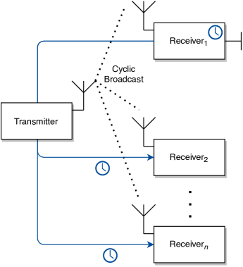
This means, that the system has a fixed transmitter, such as an AP or a base station (BS), that cyclically broadcasts messages to all receivers that should be synchronized. Next, each receiver makes a timestamp for each incoming message, and thus can calculate the offset to the master that informs each subscribed slave of the correct time compared to each time point, in this case Receiver1. This mechanism is also called receiver/receiver paradigm. With Receiver1 connected to the wired backbone of a facility, it can act as a time slave for time synchronization protocols such as specified in TSN and forward that time to all receivers connected to the same base station using RBIS protocol.
III-B IEEE 802.11
IEEE 802.11 defines a family of standards for WLAN, such as IEEE 802.11a/b/g/n/ac/ad. In the most recent one, which is also called Wi-Fi 5, two frequency bands can used. While on the data rate on the frequency band is limited to , a theoretical rate of can be reached using the band in combination with -MIMO [14]. In order to further increase the data rate, in a newer version of the IEEE 802.11 standard, which is called Wi-Fi 6, also physical layer technologies are adopted.
Additionally, in IEEE 802.11 WLAN two different operating modes are defined. These modes are called infrastructure and ad-hoc mode. Since the devices can only communicate peer-to-peer, this mode is not used in most installations. Therefore, we only consider infrastructure mode, where stations communicate with each other using an AP, in our investigations. Thus, our concept can only applied to this mode.
IV Extended RBIS protocol
For the application of RBIS protocol in infrastructure mode based WLAN deployments, a broadcast message is required, that is transmitted by an AP to each station. Furthermore, it has to contain an unique and non repeatable identifier, in order to be able to differentiate these messages. This is important, since each station produces a timestamp for each incoming broadcast messages that is required to calculate the time offset between stations.
Therefore, we use the so called beacon frames that are part of the management frames and include several data values, whereby an exemplary beacon frame is shown in Figure 2.
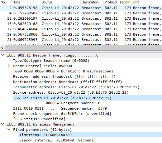
Each beacon frame contains besides the the SSID of the AP, the interval of the periodic beacon frame transmission. This value is called beacon interval (BI) and is by default 100, i. e. 102.4 ms, whereby a lower value represents a higher broadcast frequency. How often the beacon frame should be transmitted is a trade off between synchronization accuracy and required data rate, since latter will be reduced with an higher amount of beacon frames transmitted. In addition, each beacon frame includes the beacon frame timestamp. This value states the time of the AP, which is typically the time since the AP was turned on.
As mentioned earlier, the RBIS protocol implies the assumption that all ICPSs are connected to the same AP, which is not suitable for covering the entire factory floor. To enable scenarios where ICPSs are connected to different APs, our concept for extending RBIS, which is shown in Figure 3, also integrates this feature.
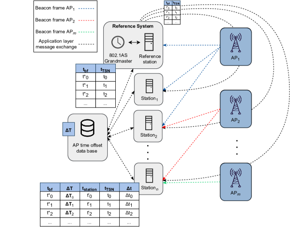
The concept consists of multiple APs and stations, whereby one of them is specified as “Reference Station”. This special station is part of the “Reference System” and is connected to the wired TSN network and can therefore not be mobile. The reason for this is that the station is time synchronized by the grandmaster (GM), which is located in the wireline TSN network. Therefore, the station that is used as Reference Station has to support time synchronization based on IEEE 802.1AS.
In the first step, the Reference System timestamps each incoming beacon timestamp with its TSN time. Afterwards, it sends the correct timestamp for each beacon frame to all other stations that shlould be time synchronized.
Next, each station couples the timestamp of its local time for each incoming beacon frame with the beacon frame timestamp. These tuples can then be used, in order to calculate the time offset.
After this this procedure, each station connected to the same AP is time synchronized, e. g. Station1 and Station2 in Figure 3. If Station2 would move to an other location on the factory floor, AP1 might be not longer be in its range and might be connected to an other AP, e. g., AP2. If we assume that Station2 is in range of both APs, and publishes their time offsets to a database, Stationn can be time synchronized with Station1 even if they are not connected to the same AP. Next, the equation for the correction of the clock for each sation can be determined.
| (1) |
Here, is the beacon frame timestamp, is the time of the Reference Station for at the arrival of the beacon frame, is the local time of the station that should be synchronized for the same beacon frame, is the current time of the station, and is the offset of both APs. If there is a lot of mobility in the system, it may be advantageous for the AP time offset database to publish the offsets between each of the APs cyclically, rather than being requested acyclically by each station. An offset matrix with dimensions , rows, and columns can be formed, where is the number of APs:
| (2) |
Since each and each , the number of entries in the database and thus the payload of the data packets can be calculated by the upper triangular matrix of a square matrix minus the values in its main diagonal:
| (3) |
Depending on the number of handovers of stations between APs and the number of APs, the calculated can be used to apply a tailored strategy, e. g., higher accuracy due to cyclic publishing or less consumed bandwidth when the channel is busy.
V Testbed & Evaluation
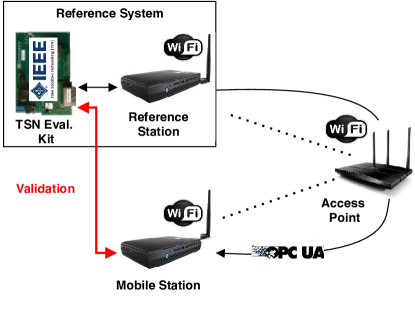
In order to validate our approach, it is evaluated on the basis of the testbed, which is shown in Figure 4. Furthermore, the testbed is equipped with the COTS components specified in Table II. This guarantees the possibility to integrate the concept in existing WLAN installations without any hardware change.
| Equipment | QTY | Specification |
| Mini PC | 2 | Intel Core i7-8809G, 2x16 GB DDR4, Intel i210-AT & i219-LM Gibgabit NICs, Ubuntu 18.04.3 LTS 64-bit, Linux 4.18.0-18-lowlatency |
| Wi-Fi Adapter | 2 | USB, Wi-Fi 5 |
| Wi-Fi Router | 1 | IEEE 802.11ac, Wi-Fi 5 |
| TSN Evaluation Kit | 1 | RAPID-TSNEK-V0001, IEEE 802.1AS |
In the testbed, two personal computers (PCs) are connected via an Wi-Fi router. Since Wi-Fi modules are typically multiplexing in order to listen to Wi-Fi signals in various channels, not all beacon frames are received by default. Therefore, the Wi-Fi network interfaces have to be set to a special monitoring mode. Using aricrack-ng module [15], a complete channel can continuously monitored. However, this leads to the drawback that it is not possible anymore to send IPv4 messages over the network. Since this is required to submit offset correction messages, an additional Wi-Fi adapter per PC was added.
Furthermore, a TSN evaluation kit is used. It is connected to the reference station and serves as TSN GM. In order to allow time synchronization, the reference station uses Linux PTP module [16]. Linux PTP is an open source implementation of IEEE 802.1AS and 802.1AS-REV specifications. In addition, the TSN GM is connected to the mobile station. With the help of the GM the clock of the mobile station can be compared to the correct TSN time and both, clock offset and accuracy of the synchronization can be determined. Therefore, Figure 5 shows the results for the measurements of three different scenarios. First, the synchronization precision that can be achieved with this equipment using wireline is shown in Figure 5a. Here, the median is 52 ns and the maximum value 254 ns. It can be seen, that the achieved synchronicity is sufficient to address each of the proposed use case classes.
The accuracy of transmitting IEEE 1588 protocol directly via plain Wi-Fi, as it is done in wireline systems, is shown in Figure 5b. Here, it can be seen, that this method is not suitable, even if at least some use cases of use case class II could be realized if only the median value is considered, which is with 0.95 ms below the limit of 1 ms. However, there are too many outliers that are located in a range up to several ms. Therefore, the required synchronicity is not fulfilled for industrial use cases of use case class II. Last but not least, Figure 5c shows the values by using RBIS protocol for synchronization of the stations. Here, the median is 13 µs and the highest measured value is 40 µs. Therefore, the synchronicity requirements of use case classes II and III can be fulfilled. Therefore, by using only COTS equipment, the synchronization requirements for all mandatory mobile use cases can be met.
In order to show the applicability of the proposed concept and its performance, a discrete automation demonstrator is proposed (see Figure 7). It is based of a simultaneous one-dimensional motion of two carriages on linear axes, as it is shown in Figure 6.
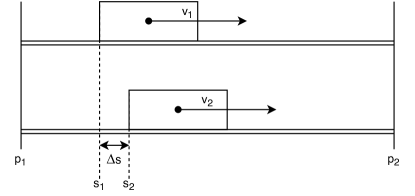
Therefore, each carriage is controlled by a different Wi-Fi station. Thus, if the mechanical movements and conditions are equal, such as the same start (p1) and end point (p2) as well as the same acceleration and velocity, the mechanical synchronicity can be calculated. Furthermore, this value can be transformed to the time synchronicity, if Equations 4 & 5 are applied.
| (4) |
| (5) |
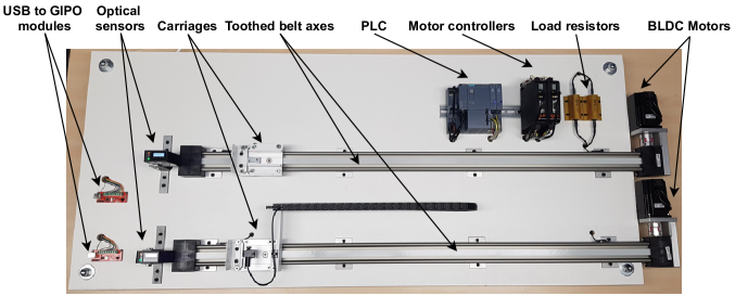
Since the demonstrator shown in Figure 7 was first proposed in [12] and both the functionalities and the hardware components are explained in detail in that paper, we only give an overview of the most important components here. It consists of two toothed belt axes, each connected to a brushless DC (BLDC) motor and is moving a carriage, which can reach a maximum speed of and an acceleration of . Furthermore, the BLDC motors are controlled by two motor controllers of the same manufacturer. Furthermore, the motor controllers have several GIPOs. With these GPIOs, setpoints for target position can be set and a movement can be triggered. Since we use mini PCs as Wi-Fi stations, it is possible to connect them to the motor controllers using USB to GPIO modules. These modules are also depicted in Figure 7. In order to detect the positions of the carriages, two high-precision sensors were installed. In high-precision mode, in which a Kalman filter uses a time series of several values to reduce the noise, the resolution is about 3-63 m depending on the position of the carriages. In order to measure the values of the position sensors, a Programmable Logic Controller (PLC) is installed, whereby each of the high-speed analog input units has a 12 bit resolution. For the validation, we performed measurements for the same three setups as for the synchronization before: (1) synchronizing two mini PCs with the standard IEEE 802.1AS (generalized Precision Time Protocol (gPTP)) synchronization mechanism without any wireless communication, (2) transmitting the IEEE 1588 (PTP) messages directly via Wi-Fi, and (3) applying the concept, proposed in this paper. The results are shown in Figure 8 and Table III.
| RBIS protocol | gPTP | PTP over Wi-Fi | |
| Median [mm] | 0.41 | 0.25 | 0.59 |
| Max [mm] | 3.86 | 3.39 | 41.12 |
The green horizontal line at 4 mm indicates the limit for use case class II for Equation 5 resolved to for and . Thus, several things can be observed. First, the accuracy required for the use case class II can be satisfied in a consistent manner. Second, due to the uncertainty of the mechanics of the system, no difference can be observed between wired and wireless transmission when the synchronization method of our system is used. Finally, it is shown that the identical use of wired synchronization mechanisms for wireless systems, such as Wi-Fi, does not result in a deterministic synchronization. In this case, the peak value for synchronization of PTP over Wi-Fi is more than 10 times higher compared to both other methods.
VI Conclusion
In this work, we presented the requirements and challenges for time synchronization of wireless use cases. For this purpose, we introduced use case classes and divided them into optional mobile and mandatory mobile. Furthermore, we proposed a concept capable of addressing these challenges. Afterwards, an evaluation using a testbed consisting of COTS components as well as a validation using a discrete automation demonstrator was done. It was shown that by applying the proposed method, accurate time synchronization of all mandatory mobile use cases can be achieved, by using COTS Wi-Fi components. Thus, a smooth integration into existing installations can be realized.
References
- [1] M. Gundall, J. Schneider, H.. Schotten and M. Aleksy “5G as Enabler for Industrie 4.0 Use Cases: Challenges and Concepts” In 2018 IEEE 23rd International Conference on Emerging Technologies and Factory Automation (ETFA) 1, 2018, pp. 1401–1408 DOI: 10.1109/ETFA.2018.8502649
- [2] A. Mahmood, R. Exel, H. Trsek and T. Sauter “Clock Synchronization Over IEEE 802.11—A Survey of Methodologies and Protocols” In IEEE Transactions on Industrial Informatics 13.2, 2017, pp. 907–922 DOI: 10.1109/TII.2016.2629669
- [3] C. Mannweiler, B. Gajic, P. Rost and R.. Ganesan “Reliable and Deterministic Mobile Communications for Industry 4.0: Key Challenges and Solutions for the Integration of the 3GPP 5G System with IEEE” In Mobile Communication - Technologies and Applications; 24. ITG-Symposium, 2019, pp. 1–6
- [4] M. Gundall, M. Strufe, H.. Schotten, P. Rost, C. Markwart, R. Blunk, A. Neumann, J. Grießbach, M. Aleksy and D. Wübben “Introduction of a 5G-Enabled Architecture for the Realization of Industry 4.0 Use Cases” In IEEE Access 9, 2021, pp. 25508–25521 DOI: 10.1109/ACCESS.2021.3057675
- [5] Alexander Mildner “Time Sensitive Networking for Wireless Networks-A State of the Art Analysis” In Network 33, 2019
- [6] Toni Adame, Marc Carrascosa and Boris Bellalta “Time-Sensitive Networking in IEEE 802.11 be: On the Way to Low-latency WiFi 7” In arXiv preprint arXiv:1912.06086, 2019
- [7] M. Wollschlaeger, T. Sauter and J. Jasperneite “The Future of Industrial Communication: Automation Networks in the Era of the Internet of Things and Industry 4.0” In IEEE Industrial Electronics Magazine 11.1, 2017, pp. 17–27 DOI: 10.1109/MIE.2017.2649104
- [8] Christoph Fischer, Dennis Krummacker, Michael Karrenbauer and Hans Dieter Schotten “A Modular Design Concept for Shaping Future Wireless TSN Solutions” In Information 12.1 Multidisciplinary Digital Publishing Institute, 2021, pp. 12
- [9] D. Krummacker, C. Fischer, K. Alam and M. Karrenbauer “Intra-Network Clock Synchronization for Wireless Networks: From State of the Art Systems to an Improved Solution” In 2020 2nd International Conference on Computer Communication and the Internet (ICCCI), 2020, pp. 36–44 DOI: 10.1109/ICCCI49374.2020.9145977
- [10] G. Cena, S. Scanzio, A. Valenzano and C. Zunino “The reference-broadcast infrastructure synchronization protocol” In Proceedings of 2012 IEEE 17th International Conference on Emerging Technologies Factory Automation (ETFA 2012), 2012, pp. 1–4 DOI: 10.1109/ETFA.2012.6489696
- [11] G. Cena, S. Scanzio, A. Valenzano and C. Zunino “Implementation and Evaluation of the Reference Broadcast Infrastructure Synchronization Protocol” In IEEE Transactions on Industrial Informatics 11.3, 2015, pp. 801–811 DOI: 10.1109/TII.2015.2396003
- [12] M. Gundall, C. Huber, P. Rost and R. Halfmann “Integration of 5G with TSN as Prerequisite for a Highly Flexible Future Industrial Automation: Time Synchronization based on IEEE 802.1AS” In 2020 46th Annual Conference of the IEEE Industrial Electronics Society (IECON) 1, 2020, pp. 3823–3830 IEEE
- [13] “IEEE Standard for a Precision Clock Synchronization Protocol for Networked Measurement and Control Systems” In IEEE Std 1588-2008 (Revision of IEEE Std 1588-2002), 2008, pp. 1–300 DOI: 10.1109/IEEESTD.2008.4579760
- [14] Sergiy Melnyk, Abraham Tesfay, Hans Schotten and Jason Rambach “Next Generation Industrial Radio LAN for Tactile and Safety Applications” In 22. VDE/ITG Fachtagung Mobilkommunikation, 2017
- [15] “Aircrack-ng” URL: http://www.aircrack-ng.org/
- [16] Richard Cochran “The Linux PTP Project” Sourceforge, 2015 URL: http://linuxptp.sourceforge.net/