Precision tomography of a three-qubit donor quantum processor in silicon
Nuclear spins were among the first physical platforms to be considered for quantum information processing[1, 2], because of their exceptional quantum coherence[3] and atomic-scale footprint. However, their full potential for quantum computing has not yet been realized, due to the lack of methods to link nuclear qubits within a scalable device combined with multi-qubit operations with sufficient fidelity to sustain fault-tolerant quantum computation. Here we demonstrate universal quantum logic operations using a pair of ion-implanted 31P donor nuclei in a silicon nanoelectronic device. A nuclear two-qubit controlled-Z gate is obtained by imparting a geometric phase to a shared electron spin[4], and used to prepare entangled Bell states with fidelities up to 94.2(2.7)%. The quantum operations are precisely characterised using gate set tomography (GST)[5], yielding one-qubit average gate fidelities up to 99.95(2)%, two-qubit average gate fidelity of 99.37(11)% and two-qubit preparation/measurement fidelities of 98.95(4)%. These three metrics indicate that nuclear spins in silicon are approaching the performance demanded in fault-tolerant quantum processors [6]. We then demonstrate entanglement between the two nuclei and the shared electron by producing a Greenberger-Horne-Zeilinger three-qubit state with 92.5(1.0)% fidelity. Since electron spin qubits in semiconductors can be further coupled to other electrons[7, 8, 9] or physically shuttled across different locations[10, 11], these results establish a viable route for scalable quantum information processing using donor nuclear and electron spins.
Nuclear spins are the most coherent quantum systems in the solid state [3, 12], owing to their extremely weak coupling to the environment. In the context of quantum information processing, the long coherence is associated with record single-qubit gate fidelities [13]. However, the weak coupling poses a challenge for multi-qubit logic operations. Using spin-carrying defects in diamond [14] and silicon carbide [15], this problem can be addressed by coupling multiple nuclei to a common electron spin, thus creating quantum registers that can sustain small quantum logic operations and error correction [16]. Exciting progress is being made on linking several such defects via optical photons [17, 18].
Still missing, however, is a pathway to exploit the atomic-scale dimension of nuclear spin qubits to engineer scalable quantum processors, where densely-packed qubits are integrated and operated within a semiconductor chip [19]. This requires entangling the nuclear qubits with electrons that can either be physically moved, or entangled with other nearby electrons. It also requires interspersing the electron-nuclear quantum processing units with spin readout devices [20]. Here we show experimentally that silicon - the material underpinning the whole of modern digital information technology - is the natural system in which to develop dense nuclear spin based quantum processors [1].
One electron – two nuclei quantum processor
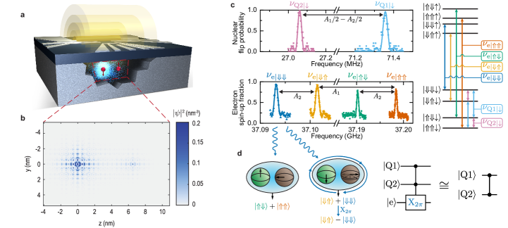
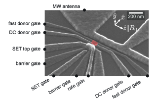
The experiments are conducted on a system of two 31P donor atoms, introduced in an isotopically purified 28Si substrate by ion implantation (see Methods). A three-qubit processor is formed by using an electron (e) with spin (basis states ) and two nuclei (Q1, Q2) with spin (basis states ). Metallic structures on the surface of the chip provide electrostatic control of the donors, create a single-electron transistor (SET) charge sensor, and deliver microwave and radiofrequency signals through a broadband antenna (Fig. 1a, Extended Data Fig. Extended data figures and tables). With this setup, we can perform single-shot electron spin readout [20], and high fidelity () single-shot quantum nondemolition readout of the nuclear spins [21], as well as nuclear magnetic resonance (NMR) and electron spin resonance (ESR) [22] on all spins involved (see Methods).
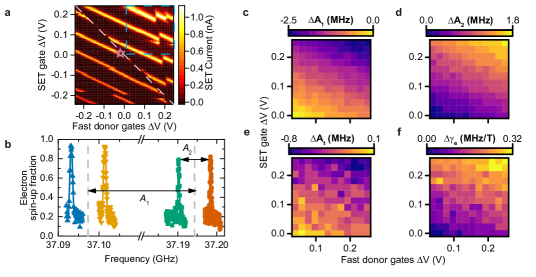
The ESR spectra in Fig. 1c exhibit four resonances. This means that the ESR frequency depends upon the state of two nuclei, to which the electron is coupled by contact hyperfine interactions MHz and MHz, with a dependence on the gate potentials caused by the Stark shift (Extended Data Fig. Extended data figures and tables). We adopt labels where, for instance, represents the frequency at which the electron spin undergoes transitions conditional on the two nuclear spin qubits being in the state, and so on. The values of can be independently checked by measuring the frequencies at which each nucleus responds while the electron is in the state (Supplementary Information S1). The hyperfine-coupled electron could either be the first or the third electron bound to the donor cluster. Since its spin relaxation time is three orders of magnitude shorter than expected from a one-electron system (Extended Data Fig. Extended data figures and tables), we interpret the ESR spectrum in Fig. 1c as describing the response of the third electron bound to a 2P donor system.
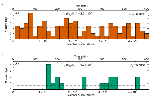
An effective-mass calculation of the wavefunction of the third electron in a 2P system (see Methods) reproduces the observed values of and by assuming donors spaced nm apart, and subjected to an electric field 2 mV/nm that pulls the electron wavefunction more strongly towards donor 1 (Fig. 1b). The 31P nuclei in this 2P cluster are spaced more widely than those produced by scanning probe lithography [8, 23], where the sub-nanometre inter-donor spacing causes a strongly anisotropic hyperfine coupling, which randomizes the nuclear spin state each time the electron is removed from the cluster for spin readout [24]. Here, instead, the probability of flipping a nuclear spin by electron ionisation is of order (Extended Data Fig. Extended data figures and tables), meaning that our nuclear readout is almost perfectly quantum nondemolition.
Nuclear two-qubit operations
We first consider the two 31P nuclear spins as the qubits of interest. One-qubit logic operations are trivially achieved by NMR pulses [21] (Methods and Extended Data Fig. Extended data figures and tables), where provides the spectral selectivity to address each qubit individually (Fig. 1c). Two-qubit operations are less trivial, since the nuclei are not directly coupled to each other (Supplementary Information S1 and S9). They are, however, hyperfine-coupled to the same electron. This allows the implementation of a geometric two-qubit controlled-Z (CZ) gate [4, 16].
When a quantum two-level system is made to trace a closed trajectory on its Bloch sphere, its quantum state acquires a geometric phase equal to half the solid angle enclosed by the trajectory [25]. Fig. 1d illustrates how an electron -pulse at the frequency (see Fig. 1d) constitutes a nuclear CZ 2-qubit gate. Starting from the state , the electron pulse at introduces a phase factor to the branch of the superposition, resulting in the state , i.e. a rotation of Q2 by 180 degrees around the -axis of its Bloch sphere, which is the output of a CZ operation. Conversely, if the initial state of Q1 were , the pulse at would have no effect on the electron, leaving the nuclear qubits unaffected.
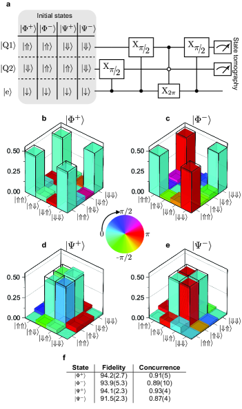
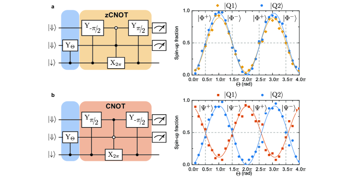
A nuclear controlled-NOT (CNOT) gate is obtained by sandwiching the CZ gate between a nuclear and pulse (Extended Data Fig. Extended data figures and tablesa). Applying an ESR pulse at transforms the sequence into a zero-CNOT gate, i.e. a gate that flips Q2 when Q1 is in the state (Extended Data Fig. Extended data figures and tablesb, and Supplementary Information S2).
We apply this universal gate set (Fig. 2a) to produce each of the four maximally-entangled Bell states of the two nuclear spins, and . We reconstruct the full density matrices of the Bell states using maximum likelihood quantum state tomography [26] (Supplementary Information S3). The reconstructed states (Fig. 2f) have fidelities of up to 94.2(2.7)%, and concurrences as high as 0.93(4), proving the creation of genuine two-qubit entanglement. Here and elsewhere, error bars indicate confidence intervals. Bell fidelities and concurrences are calculated without removing state preparation and measurement (SPAM) errors (Extended Data Table Extended data figures and tables).
Gate set tomography
We used a customized, efficient gate set tomography (GST) [27, 28, 5] analysis (see Methods, Extended Data Figs. Extended data figures and tables, Extended data figures and tables, Extended data figures and tables and Supplementary Information S4, S5, S8) to investigate the quality of six logic operations on two nuclear-spin qubits: and rotations on Q1 and Q2, an additional rotation on Q2, and the entangling CZ gate. No two single-qubit operations are ever performed in parallel. GST probes these six logic operations and reconstructs a full two-qubit model for their behavior. Earlier experiments on electron spins in silicon used randomized benchmarking (RB) [29, 30] to extract a single number for the average fidelity of all logic operations. Characterising specific gates required “interleaved” RB, which can suffer systematic errors [31, 32]. Most importantly, RB does not reveal the cause or nature of the errors. Our GST method enables measuring each gate’s fidelity to high precision, distinguishing the contributions of stochastic and coherent errors, and separating local errors (on the target qubit) from crosstalk errors (on, or coupling to, the undriven spectator qubit).
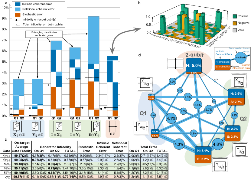
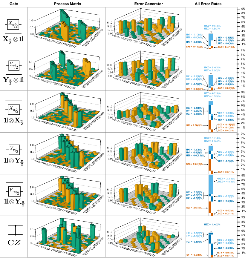
GST estimates a two-qubit process matrix for each logic operation () using maximum likelihood estimation. We represent each as the composition of its ideal target unitary process () with an error process written in terms of a Lindbladian generator (): . Each gate’s error generator (EG) can be written as a linear combination of independent elementary EGs that describe distinct kinds of error [33]. Each elementary EG’s coefficient in is the rate (per gate) at which that error builds up. Any Markovian error process can be described using just four kinds of elementary EGs: Hamiltonian (H), indexed by a single two-qubit Pauli operator, cause coherent or unitary errors (e.g., generates a coherent rotation); Pauli-stochastic (S), also indexed by a single Pauli, cause probabilistic Pauli errors (e.g. causes probabilistic errors on Q2); Pauli-correlation (C), and active (A), indexed by two Paulis, describe more exotic errors (see Methods) that were not detected in this experiment. We found that each gate’s behavior could be described using just 13-14 elementary EGs: 3 local S errors and 3 local H errors acting on each of Q1 and Q2, and 1-2 entangling H errors (discussed in detail below). Extended Data Figure Extended data figures and tables shows those errors’ rates, along with the process matrices and full EGs used to derive them. To get a higher-level picture of gate quality, we aggregate the rates of related errors (see Methods) to report total rates of stochastic and coherent errors on each qubit and on the entire 2-qubit system. We present two overall figures of merit in Figure 3a,c: generator infidelity and total error. Generator infidelity is closely related to entanglement infidelity, which accurately predicts average gate performance in realistic large-scale quantum processors and can be compared to fault-tolerance thresholds (see Methods and Supplementary Information S9). Total error is related to diamond norm (see Supplementary Information S9) and estimates worst-case gate performance in any circuit, including structured or periodic circuits. In Fig. 3c, we additionally report each gate’s average gate fidelity on its target to ease comparison of these results with those from the literature.
The process matrices estimated by GST are not unique. An equivalent representation of the gate set can be constructed by a gauge transformation [34, 5] in which all process matrices are conjugated by some invertible matrix, . Some gate errors, such as over/under-rotations or errors on idle spectator qubits, are nearly unaffected by choice of gauge; they are intrinsic to that gate. But other errors, such as a tilted rotation axis, can be shifted from one gate to another by changing gauge. These relational errors cannot be objectively associated with any particular gate. Recognizing this, we divide coherent errors into intrinsic and relational components (Fig. 3a,c). Intrinsic errors perturb a gate’s eigenvalues, whereas relational errors perturb its eigenvectors. In Fig. 3a,c we follow standard GST practice by choosing a gauge that makes the gates as close to their targets as possible. This associates relational errors with individual gates, in a way that depends critically on the choice of gauge. But the magnitude of a given relational error between a set of gates is gauge-invariant, and Fig. 3d illustrates the total relational error between each pair of gates. In this work, we found evidence only for pairwise relational errors, although more complex multi-gate relational errors are possible.
All 6 gates achieved on-target fidelities , with infidelities as low as on Q1 and on Q2. However, we observed significant crosstalk on the spectator qubit during 1-qubit gates, resulting in full logic operations (1-qubit gate and spectator idle operation in parallel) with higher infidelities of . Remarkably, the CZ gate’s infidelity of is almost on par with the single-qubit gates – a rare scenario in multi-qubit systems (Fig. 3a,c).
SPAM errors were estimated by GST as 1.05(4)% on average, and as low as 0.25(3)% for the state (Extended Data Table Extended data figures and tables). This is a unique feature of nuclear spin qubits, afforded by the quantum nondemolition nature of the measurement process [21] (Methods and Extended Data Fig. Extended data figures and tables).
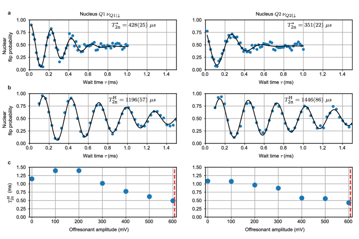
GST provided unambiguous evidence for a surprising relational error: weight-2 (entangling) and/or coherent errors on each 1-qubit gate , with amplitudes from (Extended Data Figure Extended data figures and tables). These errors are consistent with an intermittent Hamiltonian during the gate pulses. After ruling out a wide range of possible error channels, we propose that the observed error arises from the spurious accumulation of geometric phase by the electron spin, caused by off-resonance leakage of microwave power near the ESR frequencies (Supplementary Information S9). This observation illustrates the diagnostic power of GST, which revealed an error channel we had not anticipated. It also shows GST’s ability to unveil correlated and entangling errors, whose detection and prevention is of key importance for the realization of fault-tolerant quantum computers [35].
Three-qubit entanglement
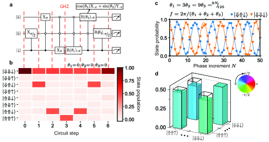
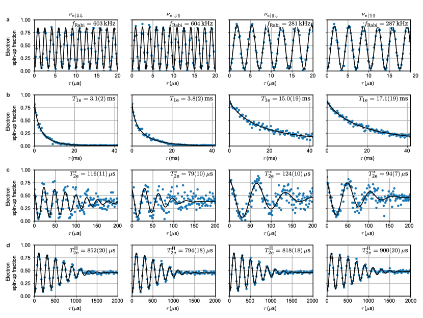
The nuclear logic gates shown above would not scale beyond a single, highly localized cluster of donors. However, adding the hyperfine-coupled electron qubit yields a scalable heterogeneous architecture. Electron qubits decohere faster (see Extended Data Figs. Extended data figures and tables and Extended data figures and tables for a comparison), but admit faster control. If high-fidelity entanglement between electron and nuclear qubits can be created, electron qubits can enable fast coherent communication between distant nuclei (via electron-electron entanglement, or physical shuttling) or serve as high-fidelity ancilla qubits for quantum error correction. To demonstrate this capability, we produce the maximally entangled three-qubit Greenberger-Horne-Zeilinger (GHZ) state using the pulse sequence shown in Fig. 4a. Starting from , an NMR pulse at creates a coherent superposition state of nucleus 2, followed by a nuclear zCNOT gate (as in Fig. 2a) to produce a nuclear state, and an ESR pulse at to arrive at . Since the ESR frequency directly depends on the state of both nuclei, the latter pulse constitutes a natural 3-qubit Toffoli gate, making the creation of 3-qubit entanglement particularly simple, as in nitrogen-vacancy centres in diamond [36]. Executing Toffoli gates on electrons in quantum dots [37] requires more complex protocols, but can be simplified by a combination of exchange and microwave pulses [38].
Measuring the populations of the eight electron-nuclear states (Supplementary Information S7) after each step confirms the expected evolution from to (Fig. 4b). The evolution can be undone by applying the sequence in reverse, yielding a return probability to of 89.6(9)%, including SPAM errors. As in the two-qubit case, measuring the populations is a useful sanity check but does not prove multipartite entanglement, which requires knowing the off-diagonal terms of the density matrix .
Standard tomography methods require measuring the target state in different bases, obtained by rotating the qubits prior to measurement. However, the superposition of and dephases at a rate dominated by the electron dephasing time s (Extended Data Fig. Extended data figures and tables), which is only marginally longer than the nuclear spin operation time s. Therefore, the GHZ state will have significantly dephased by the time it is projected onto each measurement basis.
We circumvent this problem by adopting a tomography method that minimises the time spent in the GHZ state. An extension of a method first introduced for the measurement of electron-nuclear entanglement in spin ensembles [39], it is related to the parity scan commonly used in trapped ions [40] and superconducting circuits [41]. We repeat the reversal of the GHZ state (Fig. 4b) times, each time introducing phase shifts to the rotation axes of the three reversal pulses, with . The return probability to oscillates with ; the amplitude and phase of the oscillations yield the off-diagonal matrix element .
Since the ideal has nonzero elements only on its four corners, the populations and the coherence are sufficient to determine the GHZ state fidelity . Also here, SPAM errors remain included in total infidelity. By comparison, an 88% GHZ state fidelity has been reported in a triple quantum dot after removing SPAM errors, whereas the uncorrected fidelity is 45.8% [37]. This highlights the drastic effect of SPAM of multi-qubit entanglement, and the robustness of our system against such errors. The different coherence and operation timescales for electron and nuclei need not be an obstacle for the use of such entangled states in scaled-up architectures, because all further entangling or shuttling operations between electrons will occur on s time scales.
Outlook
The demonstration of 1-qubit, 2-qubit and SPAM errors at or below the 1% level highlight the potential of nuclear spins in silicon as a credible platform for fault-tolerant quantum computing. An often-quoted example, based on surface code quantum error correction, sets a fault-tolerance threshold of 0.56% for the entanglement infidelity of 1- and 2-qubit gates and the SPAM errors [6].
Several avenues are available to harness the high-fidelity operations demonstrated here. Replacing the 31P donors with the higher-spin group-V analogues such as 123Sb () or 209Bi () would provide access to a much larger Hilbert space in which to encode quantum information. For example, a cluster of two 123Sb donors contains the equivalent of six qubits in the nuclear spins, plus an electron qubit. An error-correcting code can be efficiently implemented in high-spin nuclei [42], where our method would provide a pathway for universal operations between the logical qubits encoded in each nucleus.
Moving to heavier group-V donors also allows the electrical control of the nuclear spins [43]. Combined with the electrical drive of the electron-nuclear ‘flip-flop’ transition [44], this implies the ability to control electron and nuclei by purely electrical means. In a two-donor system as shown here, the entangling CZ gate could similarly be obtained by an electrical -pulse on a flip-flop transition.
The electron-nuclear entanglement we have demonstrated can be harnessed to scale up beyond a pair of nuclei coupled to the same electron. Neighbouring donor electrons can be entangled via exchange interaction by performing controlled-rotation resonant gates [9] or gates [8]. Wider distances could be afforded by physically shuttling the electron across lithographic quantum dots [45, 46], while preserving the quantum information encoded in it [11]. Our methods would apply equally to isoelectronic nuclear spin centres like 73Ge and 29Si, where it has been shown that the nuclear qubit coherence is preserved while shuttling the electron across neighbouring dots [10]. Furthermore, electron spins can mediate the coherent interaction between nuclear spin qubits and microwave photons [47, 48]. Recent experiments on electron spin qubits in silicon report 1- and 2-qubit gate fidelities above 99% [49, 50]. Therefore, the fidelity of electron qubit operations will not constitute a bottleneck for the performance of electron-nuclear quantum processors. These examples illustrate the significance of universal high-fidelity two-qubit operations with nuclear spins in a platform like silicon, which can simultaneously host nuclear and electron spin qubits, lithographic quantum dots, and dense readout and control devices [19].
References
- [1] Kane, B. E. A silicon-based nuclear spin quantum computer. Nature 393, 133 (1998).
- [2] Vandersypen, L. M. & Chuang, I. L. NMR techniques for quantum control and computation. Reviews of Modern Physics 76, 1037 (2005).
- [3] Saeedi, K. et al. Room-temperature quantum bit storage exceeding 39 minutes using ionized donors in silicon-28. Science 342, 830 (2013).
- [4] Filidou, V. et al. Ultrafast entangling gates between nuclear spins using photoexcited triplet states. Nature Physics 8, 596–600 (2012).
- [5] Nielsen, E. et al. Gate set tomography. Quantum 5, 557 (2021).
- [6] Fowler, A. G., Mariantoni, M., Martinis, J. M. & Cleland, A. N. Surface codes: Towards practical large-scale quantum computation. Physical Review A 86, 032324 (2012).
- [7] Harvey-Collard, P. et al. Coherent coupling between a quantum dot and a donor in silicon. Nature Communications 8, 1029 (2017).
- [8] He, Y. et al. A two-qubit gate between phosphorus donor electrons in silicon. Nature 571, 371–375 (2019).
- [9] Mądzik, M. T. et al. Conditional quantum operation of two exchange-coupled single-donor spin qubits in a MOS-compatible silicon device. Nature Communications 12, 181 (2021).
- [10] Hensen, B. et al. A silicon quantum-dot-coupled nuclear spin qubit. Nature Nanotechnology 15, 13–17 (2020).
- [11] Yoneda, J. et al. Coherent spin qubit transport in silicon. Nature Communications 12, 4114 (2021).
- [12] Zhong, M. et al. Optically addressable nuclear spins in a solid with a six-hour coherence time. Nature 517, 177–180 (2015).
- [13] Muhonen, J. T. et al. Quantifying the quantum gate fidelity of single-atom spin qubits in silicon by randomized benchmarking. Journal of Physics: Condensed Matter 27, 154205 (2015).
- [14] Bradley, C. et al. A ten-qubit solid-state spin register with quantum memory up to one minute. Physical Review X 9, 031045 (2019).
- [15] Bourassa, A. et al. Entanglement and control of single nuclear spins in isotopically engineered silicon carbide. Nature Materials 19, 1319–1325 (2020).
- [16] Waldherr, G. et al. Quantum error correction in a solid-state hybrid spin register. Nature 506, 204–207 (2014).
- [17] Bhaskar, M. K. et al. Experimental demonstration of memory-enhanced quantum communication. Nature 580, 60–64 (2020).
- [18] Pompili, M. et al. Realization of a multinode quantum network of remote solid-state qubits. Science 372, 259–264 (2021).
- [19] Vandersypen, L. et al. Interfacing spin qubits in quantum dots and donors—hot, dense, and coherent. npj Quantum Information 3, 34 (2017).
- [20] Morello, A. et al. Single-shot readout of an electron spin in silicon. Nature 467, 687–691 (2010).
- [21] Pla, J. J. et al. High-fidelity readout and control of a nuclear spin qubit in silicon. Nature 496, 334–338 (2013).
- [22] Pla, J. J. et al. A single-atom electron spin qubit in silicon. Nature 489, 541–545 (2012).
- [23] Ivie, J. A. et al. Impact of Incorporation Kinetics on Device Fabrication with Atomic Precision. Physical Review Applied 16, 054037 (2021).
- [24] Hile, S. J. et al. Addressable electron spin resonance using donors and donor molecules in silicon. Science Advances 4, eaaq1459 (2018).
- [25] Anandan, J. The geometric phase. Nature 360, 307–313 (1992).
- [26] James, D. F. V., Kwiat, P. G., Munro, W. J. & White, A. G. Measurement of qubits. Physical Review A 64, 052312 (2001).
- [27] Dehollain, J. P. et al. Optimization of a solid-state electron spin qubit using gate set tomography. New Journal of Physics 18, 103018 (2016).
- [28] Blume-Kohout, R. et al. Demonstration of qubit operations below a rigorous fault tolerance threshold with gate set tomography. Nature Communications 8, 14485 (2017).
- [29] Huang, W. et al. Fidelity benchmarks for two-qubit gates in silicon. Nature 569, 532–536 (2019).
- [30] Xue, X. et al. Benchmarking gate fidelities in a Si/SiGe two-qubit device. Physical Review X 9, 021011 (2019).
- [31] Kimmel, S., da Silva, M. P., Ryan, C. A., Johnson, B. R. & Ohki, T. Robust extraction of tomographic information via randomized benchmarking. Physical Review X 4, 011050 (2014).
- [32] Carignan-Dugas, A., Wallman, J. J. & Emerson, J. Bounding the average gate fidelity of composite channels using the unitarity. New Journal of Physics 21, 053016 (2019).
- [33] Blume-Kohout, R. et al. A taxonomy of small markovian errors. arXiv preprint arXiv:2103.01928 (2021).
- [34] Proctor, T., Rudinger, K., Young, K., Sarovar, M. & Blume-Kohout, R. What randomized benchmarking actually measures. Physical Review Letters 119, 130502 (2017).
- [35] Novais, E. & Mucciolo, E. R. Surface code threshold in the presence of correlated errors. Physical Review Letters 110, 010502 (2013).
- [36] Neumann, P. et al. Multipartite entanglement among single spins in diamond. Science 320, 1326–1329 (2008).
- [37] Takeda, K. et al. Quantum tomography of an entangled three-qubit state in silicon. Nature Nanotechnology 16, 965–969 (2021).
- [38] Gullans, M. & Petta, J. Protocol for a resonantly driven three-qubit toffoli gate with silicon spin qubits. Physical Review B 100, 085419 (2019).
- [39] Mehring, M., Mende, J. & Scherer, W. Entanglement between an electron and a nuclear spin 1/2. Physical Review Letters 90, 153001 (2003).
- [40] Sackett, C. A. et al. Experimental entanglement of four particles. Nature 404, 256–259 (2000).
- [41] Wei, K. X. et al. Verifying multipartite entangled greenberger-horne-zeilinger states via multiple quantum coherences. Physical Review A 101, 032343 (2020).
- [42] Gross, J. A., Godfrin, C., Blais, A. & Dupont-Ferrier, E. Hardware-efficient error-correcting codes for large nuclear spins. arXiv preprint arXiv:2103.08548 (2021).
- [43] Asaad, S. et al. Coherent electrical control of a single high-spin nucleus in silicon. Nature 579, 205–209 (2020).
- [44] Tosi, G. et al. Silicon quantum processor with robust long-distance qubit couplings. Nature Communications 8, 450 (2017).
- [45] Pica, G., Lovett, B. W., Bhatt, R. N., Schenkel, T. & Lyon, S. A. Surface code architecture for donors and dots in silicon with imprecise and nonuniform qubit couplings. Physical Review B 93, 035306 (2016).
- [46] Buonacorsi, B. et al. Network architecture for a topological quantum computer in silicon. Quantum Science and Technology 4, 025003 (2019).
- [47] Tosi, G., Mohiyaddin, F. A., Tenberg, S., Laucht, A. & Morello, A. Robust electric dipole transition at microwave frequencies for nuclear spin qubits in silicon. Physical Review B 98, 075313 (2018).
- [48] Mielke, J., Petta, J. R. & Burkard, G. Nuclear spin readout in a cavity-coupled hybrid quantum dot-donor system. PRX Quantum 2, 020347 (2021).
- [49] Xue, X. et al. Quantum logic with spin qubits crossing the surface code threshold. Nature 601, 343–347 (2022).
- [50] Noiri, A. et al. Fast universal quantum gate above the fault-tolerance threshold in silicon. Nature 601, 338–342 (2022).
Methods
Device fabrication
The quantum processor is fabricated using methods compatible with standard silicon MOS processes. We start from a high quality silicon substrate (p-type 100; 10-20 cm), on top of which a 900 nm thick epilayer of isotopically enriched 28Si has been grown using low-pressure chemical vapour deposition (LPCVD). The residual 29Si concentration is 730 ppm. Heavily-doped n+ regions for Ohmic contacts and lightly-doped p regions for leakage prevention are defined by thermal diffusion of phosphorus and boron, respectively. A 200 nm thick SiO2 field oxide is grown in a wet oxidation furnace. In the centre of the device, an opening of 20 m 40 m is etched in the field oxide using HF acid. Immediately after, a 8 nm thick, high quality dry SiO2 gate oxide is grown in this opening. In preparation for ion implantation, a 90 nm 100 nm aperture is opened in a PMMA mask using electron-beam-lithography (EBL). The samples are implanted with P+ ions at an acceleration voltage of 10 keV per ion. During implantation the samples were tilted by 8 degrees and the fluence was set at . Donor activation and implantation damage repair is achieved through the process of a rapid thermal annealing (5 seconds at 1000 ∘C). The gate layout is patterned around the implantation region in three EBL steps, each followed by aluminium thermal deposition (25 nm thickness for layer 1; 50 nm for layer 2; 100 nm for layer 3). Immediately after each metal deposition, the sample is exposed to a pure, low pressure (100 mTorr) oxygen atmosphere to form an Al2O3 layer, which electrically insulated the overlapping metal gates. At the last step, samples are annealed in a forming gas (400 ∘C, 15 min, 95 N2 / 5 H2) aimed at passivating the interface traps.
Experimental setup
The device was wire-bonded to a gold-plated printed circuit board and placed in a copper enclosure. The enclosure was placed in a permanent magnet array [1], producing a static magnetic field of 1.33 T at the device (see Extended Data Fig. Extended data figures and tables for field orientation). The board was mounted on a Bluefors BF-LD400 cryogen-free dilution refrigerator, reaching a base temperature of 14 mK, while the effective electron temperature was mK.
DC bias voltages were applied to all gates using Stanford Research Systems (SRS) SIM928 voltage sources. A room-temperature resistive combiner was used for the fast donor gates (Extended Data Fig. Extended data figures and tables) to add DC voltages to AC signals produced by the LeCroy Arbstudio 1104, which then passed through an 80 MHz low-pass filter; all other gates passed through a 20 Hz low-pass filter. All filtering takes place at the mixing chamber plate. The wiring includes graphite-coated flexible coaxial cables to reduce triboelectric noise [2].
Microwave pulses to induce ESR transitions were applied to an on-chip broadband antenna [3] using a Rohde & Schwarz SGS100A vector microwave source combined with an SGU100A upconverter. The microwave carrier frequency remained fixed at GHz, while the output frequency was varied within a pulse sequence by mixing it with a radiofrequency (RF) signal using double-sideband modulation, i.e. by applying RF pulses to the in-phase port of the SGS100A IQ mixer (the quadrature port was terminated by a 50 load). The carrier frequency was chosen such that whenever one sideband tone was resonant with an ESR pulse, the second sideband was off-resonant with all other ESR frequencies. To suppress microwave signals when not needed, 0 V was applied to the in-phase port of the IQ mixer. Under these circumstances, the carrier frequency is expected to be suppressed by 35 dB, according to the source data sheet. The RF pulses used for double-sideband modulation were generated by one of the two channels of the Agilent 81180A arbitrary waveform generator; the second channel delivered RF pulses to the microwave antenna to drive NMR transitions. The microwave signal for ESR and RF signal for NMR were combined in a Marki Microwave DPX-1721 diplexer.
The SET current passed through a Femto DLPCA-200 transimpedance amplifier ( V/A gain, 50 kHz bandwidth), followed by an SRS SIM910 JFET post-amplifier ( V/V gain), SRS SIM965 analog filter (50 kHz cutoff low-pass Bessel filter), and acquired via an AlazarTech ATS9440 PCI digitizer card. The instruments were triggered by a SpinCore PulseBlasterESR-PRO. The measurements instruments were controlled by Python code using the quantum measurement software packages QCoDeS and SilQ.
System Hamiltonian
The static Hamiltonian of our combined electron-nuclei system is
| (1) |
where GHz T-1 is the electron gyromagnetic ratio [4], MHz T-1 is the nuclear gyromagnetic ratio [5], are the electron spin operators, and are the nuclear spin operators for nucleus . The static magnetic field is aligned along , and , () is the hyperfine interaction strength between the electron and nucleus 1 (2).
An AC drive applied to the microwave line is used to induce transitions between nuclear spin states and between electron spin states. The drive predominantly modulates the transverse magnetic field as
| (2) |
where is the oscillating magnetic field strength, primarily aligned along .
Electron spin readout
An electron spin readout is realized through the spin to charge conversion [6, 7]. This method utilizes a single electron transistor (SET) as both a charge sensor and an electron reservoir. The electron spin and states are separated by the Zeeman energy, which scales linearly with the external magnetic field. Thermal broadening of the SET at 100 mK is much smaller than the Zeeman splitting of two electron spin states. This means that, at the read position, the donor electron spin down state faces only occupied levels in the SET island (tunneling is prohibited) and the spin up state faces only unoccupied states and can freely tunnel out the SET island. This event will shift the energy ladder in the SET island, bringing it out of the Coulomb blockade, thus causing a burst in the current. This burst will last until electron tunnels to the donor. If the electron has been projected to the state then no change in the SET current will be recorded, as the electron cannot tunnel to the SET island. At the end of each read phase the electron spin is reinitialized in for the next single shot cycle. The fidelity of single-shot electron readout and initialisation by spin-dependent tunnelling is % in this device. However, we further increase the initialisation fidelity by letting the electron thermalise to the lattice temperature for a time (Fig. Extended data figures and tablesb) before triggering further operations.
Nuclear spin readout and initialisation
The readout of the two nuclear spin qubits is an extension of the well-known method developed for a single donor [21], based on the excitation of the electron bound to the nuclei, conditional on a particular nuclear state, followed by electron spin readout [20]. The same method is used to initialise the nuclei in a known state.
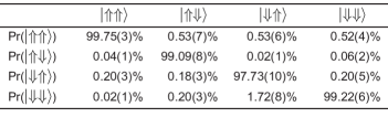
In the present system, consisting of an electron coupled to two 31P donors with different hyperfine couplings , we find four well-separated electron spin resonance (ESR) frequencies (Fig. 1c), conditional on the nuclear states. An electron in the state is initially drawn from a cold charge reservoir onto the donor cluster (independently of nuclear states). We then apply a microwave -pulse at a particular ESR frequency, for instance corresponding to the nuclear spin state, and then measure the electron spin. If it is found in the state, then the nuclear spins are projected to the state. If the electron is (i.e. the pulse at failed to flip it to ), the nuclear spins are projected to the subspace orthogonal to the state. This constitutes a nuclear spins single-shot readout, with a fidelity given by the product of the electron single-shot readout fidelity (typically %) and the electron -pulse fidelity (%).
This nuclear readout is a projective, approximately quantum non demolition (QND) process [21]. The ideal QND measurement relies on the observable to commute with the Hamiltonian describing an interaction between the observable and the measurement apparatus [8]. In our case the hyperfine terms and constitute . The observation of nuclear spin quantum jumps originating from the electron measurement by spin-dependent tunnelling (ionization shock) hints at a deviation from QND nature of the readout process [21]. It implies the presence of terms of the form in the hyperfine coupling, and possibly additional anisotropic terms, which do not commute with . In our experiment, the deviation from the ideal QND measurement is extremely small, of order , as shown in Extended Data Figure Extended data figures and tables.
We exploit the near-perfect QND nature of the nuclear spin readout by repeating the cycle [load – ESR -pulse – electron readout] between 7 and 40 times, to substantially increase the nuclear single-shot readout fidelity. This is the fundamental reason why our average SPAM errors are % (Extended Data Table Extended data figures and tables), and we have thus reported Bell and GHZ state fidelities without removing SPAM errors from the estimate.
ESR and NMR calibration
Gate calibration
Both the 1-qubit NMR gates and the 2-qubit ESR gate were iteratively calibrated using a combination of GST and other tuning methods. Rabi flops were first used to obtain roughly calibrated 1-qubit NMR gates. Next, 1-qubit GST was repeatedly employed to identify and correct error contributions such as over-/under-rotations and detunings. Other routines such as the repeated application of gates were performed in between GST measurements to independently verify the improvements to 1-qubit gate fidelities of GST. The calibrated NMR pulse duration of Q1 (Q2) is 12.0 s (25.3 s). The discrepancy between the two durations is largely due to the hyperfine interaction enhancing the Rabi frequency of Q1 and reducing the Rabi frequency of Q2, combined with line reflections and filtering.
For the geometric 2-qubit gate based upon an electron 2 pulse, we found that a trivial calibration using Rabi flops already gave a near-optimal result. GST was then used for fine-tuning and for the detection of small error contributions such as a minor frequency shift. The calibrated ESR pulse duration of the CZ gate is 1.89 s at an output power of 20 dBm.
Periodic frequency recalibration
To keep the system tuned throughout the measurements, the NMR frequencies and and ESR frequency were calibrated every ten circuits. The ESR frequency was calibrated by measuring the ESR spectrum and selecting the frequency of the ESR peak. The NMR frequencies were measured by a variant of the Ramsey sequence, consisting of an and separated by a wait time . An off-resonant RF pulse was applied during the wait time to mitigate any frequency shift caused by the absence of an RF drive. Since nuclear readout has a near-unity fidelity, this measurement should result in a nuclear flipping probability if the RF frequency matches the average NMR frequency throughout the measurement. Therefore, any deviation of from 0.5 provides a direct estimate of the frequency mismatch , provided that . A higher more accurately estimates , while a lower results in the condition being valid for a broader range of . The NMR recalibration sequence iteratively increased the wait time to ensure that the condition remains satisfied while increasing the accuracy at which the NMR frequency is estimated. For each , the NMR frequency was estimated by repeating this sequence and updating the RF frequency until fell within the range [0.4, 0.6].
Measurement overhead
Instrument setups and calibration routines add a significant overhead to the GST measurements. An estimate of this overhead can be obtained by comparing the total measurement duration to the duration of a single pulse sequence. The 2Q GST measurement shown in Fig. 3 was acquired over 61 hours, during which 300-503 shots were acquired for each of the 1593 circuits. This results in an average duration of 340 ms per GST pulse sequence iteration. Compared to the average pulse sequence duration of around 121 ms, this corresponds to an overhead of 185%.
Effective mass theory simulations of the hyperfine interaction
To simulate the wave function of the third electron in the 2P system, the effective mass theory (EMT) model of the neutral 2P system in Ref. [9] is extended in a mean-field approach.
For short donor separations, the two inner electrons are tightly bound in a magnetically inactive singlet orbital. The third electron then only interacts with the inner ones to the extent that it experiences the Coulomb repulsion of their fixed charge distribution
| (3) |
Here, is the electron charge, the dielectric constant in silicon and is the charge density of the tightly bound electrons found in Ref. [9]. The third electron is then effectively described by the sum of the 2P EMT Hamiltonian in an electric field [9] and the corresponding mean-field potential in Eq. (3).
Here, only 2P configurations along the [100] crystal axis with distances d7 nm and realistic fields E2 mV/nm are considered. In this regime the inter-donor exchange dominates the on-site exchange and the mean-field approach is justified.
The chosen basis is a combination of two STO-3G [9] orbitals, one variationally optimized at =0.5 nm and the other at =7 nm.
To compute the hyperfine interaction strength, the electron density at the nucleus is rescaled by a bunching factor of 440 [10]. The experimentally found hyperfine configuration is found for donors spaced 6.5 nm apart, and subjected to an electric field 2 mV/nm.
Gate set tomography experiments
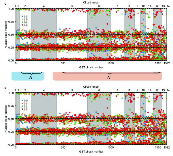
We designed a customized GST experiment for a set of 6 logic gates: and rotations on each qubit, an additional rotation on Q2, and the symmetric CZ gate between them. A basic 2-qubit GST experiment for this gate set comprises a list of quantum circuits defined by: (1) choosing a set of 75 short “germ” circuits that, when repeated, collectively amplify every error rate; (2) repeating each germ several times to times to form “germ power” circuits whose lengths are approximately ; and (3) prefacing and appending each germ power with each of 16 “preparation fiducial” circuits and each of 11 “measurement fiducial” circuits. We used , yielding a set of 20606 circuits (this is not a simple multiplication because germ circuits with depth do not appear at shorter ). We eliminated 92% of these circuits using two techniques from [5]. First, we identified a subset of 18 germs that amplify any dominant errors in each gate (if was very large, subdominant errors would get echoed away by dominant errors). This yielded a total of 50 germ powers. Second, for the germ powers, we identified and eliminated pairs of fiducial circuits that provided redundant information. This trimmed the circuits per germ power from 176 to as few as 16, and the total number of circuits from 8800 to just 1592. Each of those circuits was repeated 300-500 times to gather statistics. We used maximum likelihood estimation (MLE) implemented in the pyGSTi software [11, 12] to estimate 2-qubit process matrices for all six operations.
Constructing and selecting reduced models
Process matrices are a comprehensive, but not especially transparent, representation of gate errors. So we used each gate’s ideal target (unitary) operation to construct an error generator [33] that presents the same information more usefully. Representing noisy gates this way enables us to split each gate’s total error into parts that act on Q1 only, Q2 only, or both qubits together – and then further into coherent and stochastic errors – to reveal those errors’ sources and consequences. It also enables the construction of simple, efficient “reduced models” for gate errors, by identifying swaths of elementary error generators whose rates are indistinguishable from zero.
Pinning the coefficients of elementary error generators to zero yields a reduced model with fewer parameters, whose likelihood () can be found by MLE. We evaluate the statistical significance of error rates that were pinned by seeing how much declines. If a given error’s true rate is zero, then pinning it to zero in the model reduces , on average, by 1 [13]. So when we pin rates, we compute the “evidence ratio” , where is the difference between the two models’ likelihood [14]. If , the pinned rates are strictly negligible; if , then the smaller model is preferred by Akaike’s information criterion (AIC) [15]; other criteria (e.g. the Bayesian BIC) impose higher thresholds. We used a slightly higher threshold and chose the smaller model whenever . Using this methodology, we constructed a model that describes the data well, in which just 83 (out of ) elementary errors’ rates are significantly different from zero.
The rates of all the un-pinned elementary errors form a vector describing the noisy model. In general, un-physical gauge degrees of freedom [5] will give rise to a foliation of the model space into gauge manifolds on which the loglikelihood is constant. In our analysis, we work in the limit of small errors and gauge transformations where the space is approximately linear, and identify the subspace that is gauge invariant. We are able to construct a basis for the gauge-invariant subspace whose elements correspond to relational or intrinsic errors and have a definite type (H, S, or A), allowing us to decompose the model’s total error as shown in Figure 3.
Extended Data Figure Extended data figures and tables presents each gate’s 13-14 nonzero elementary error rates after projecting the error vector onto the gauge-invariant subspace (column 3), along with the process matrices (column 1) and error generators (column 2) from which they are derived. Here and elsewhere, error bars are confidence intervals computed using the Hessian of the loglikelihood function.
Aggregated error rates and metrics
Our GST analysis aims to identify specific gate errors and understand how these errors affect the overall performance of our system. It begins with the raw output of GST – rates of elementary errors on gates. We aggregate these error rates in different ways, yielding each gate’s total error and infidelity, and partitioning those metrics into their components on Q1 or Q2 or both qubits together, in order to summarize different aspects of system performance. We additionally report average gate fidelities to facilitate comparison with the literature.
Gate errors by definition cause unintended changes in the state of the system. S error generators produce stochastic errors that transfer probability to erroneous states; H generators produce coherent errors that transfer amplitude to erroneous states. We can interpret the rate of an error generator, to first order, as the amount of erroneous probability (denoted for S generators) or amplitude (denoted for H generators) transferred by a single use of the gate when acting on one half of a maximally entangled state.
It is useful to group similar errors together and aggregate their rates. We classify and combine error generators according to:
-
•
Their type (H or S),
-
•
Their support (Q1, Q2, or joint),
-
•
Whether they are intrinsic to a single gate, or relational between gates (H errors only; relational S errors were negligible).
The elementary error generators described in the main text have definite type and support. For example, the generator has type H and support on Q1. Any error generator on a given gate is intrinsic to that gate if it commutes with the gate, and relational otherwise. For example, if single-qubit and gates produce rotations around axes that are separated by only instead of , then either gate can be considered perfect at the cost of assigning a tilt error to the other gate. This error can be moved between the two gates by a gauge transformation that rotates both gates by around the -axis. This error is purely relational; it cannot be assigned definitively to one gate or the other, but can be unambiguously observed in circuits containing both gates.
To divide each gate’s errors into intrinsic and relational components, we represent the gate’s error generator as a vector in a space spanned by the H and S elementary error generators. Error generators that commute with the target gate form a subspace that is invariant under gauge transformations. The error generator’s projection onto this space is its intrinsic component. Error generators in the complement of the intrinsic subspace are relational – they can be changed or eliminated by gauge transformations – and the projection of the gate’s error generator onto this complement is its relational component.
To construct aggregated error metrics, we start by aggregating H and S rates separately. They add in different ways, because H error rates correspond to amplitudes while S error rates correspond to probabilities. Rates of S generators add directly (), while rates of H generators add in quadrature (). Combining H and S error rates into a single metric is trickier – there is no unique way to do so because the impact of coherent errors depends on how they interfere over the course of a circuit. We therefore consider two quantities: total error and generator infidelity . Total error approximates the maximal rate at which gate errors could add up in any circuit, while infidelity quantifies the same errors’ average impact in a random circuit.
Both of these metrics appear in Fig. 3, where in panels a, c, and d we report aggregated error rates that partition the overall error in various ways (see the discussion in S10 of the Supplement). We report a third metric, the average gate fidelity (AGF) on each gate’s target qubit[s], in Fig. 3c and in the abstract to aid comparison with other published results. The on-target AGF provides an overall (and gauge-dependent) measure of the average performance of a gate when acting only on the target qubit(s). For a gate targeting Q1, it is defined as:
| (4) |
For a two-qubit gate, the on-target AGF is simply the AGF of the two-qubit operation:
| (5) |
In both cases, is the Haar measure (over 1-qubit states in Eq. 4 and over 2-qubit states in Eq. 5) and is the error generator of the gate. Although AGF is provided for comparison to the literature, it is not a good predictor of performance in general circuits (see Supplemental Information S9), and when we use the unqualified term “fidelity”, it always denotes generator fidelity, . Section S9 of the Supplement includes an extensive discussion of overall gate error metrics and their relationships.
References
- [1] Adambukulam, C. et al. An ultra-stable 1.5 T permanent magnet assembly for qubit experiments at cryogenic temperatures. Review of Scientific Instruments 92, 085106 (2021).
- [2] Kalra, R. et al. Vibration-induced electrical noise in a cryogen-free dilution refrigerator: Characterization, mitigation, and impact on qubit coherence. Review of Scientific Instruments 87, 073905 (2016).
- [3] Dehollain, J. et al. Nanoscale broadband transmission lines for spin qubit control. Nanotechnology 24, 015202 (2012).
- [4] Feher, G. Electron spin resonance experiments on donors in silicon. I. Electronic structure of donors by the electron nuclear double resonance technique. Physical Review 114, 1219-1244 (1959).
- [5] Steger, M. et al. Optically-detected NMR of optically-hyperpolarized 31P neutral donors in 28Si. Journal of Applied Physics 109, 102411 (2011).
- [6] Elzerman, J. M. et al. Single-shot read-out of an individual electron spin in a quantum dot. Nature 430, 431–435 (2004).
- [7] Morello, A. et al. Architecture for high-sensitivity single-shot readout and control of the electron spin of individual donors in silicon. Physical Review B 80, 081307 (2009).
- [8] Braginsky, V. B. & Khalili, F. Y. Quantum nondemolition measurements: the route from toys to tools. Reviews of Modern Physics 68, 1–11 (1996).
- [9] Joecker, B. et al. Full configuration interaction simulations of exchange-coupled donors in silicon using multi-valley effective mass theory. New Journal of Physics 23, 073007 (2021).
- [10] Gamble, J. K. et al. Multivalley effective mass theory simulation of donors in silicon. Physical Review B 91, 235318 (2015).
- [11] Nielsen, E. et al. Python GST implementation (PyGSTi) v. 0.9. Tech. Rep., Sandia National Lab.(SNL-NM), Albuquerque, NM (United States) (2019).
- [12] Nielsen, E. et al. Probing quantum processor performance with pyGSTi. Quantum Science and Technology 5, 044002 (2020).
- [13] Wilks, S. S. The large-sample distribution of the likelihood ratio for testing composite hypotheses. The Annals of Mathematical Statistics 9, 60 – 62 (1938).
- [14] Nielsen, E., Rudinger, K., Proctor, T., Young, K. & Blume-Kohout, R. Efficient flexible characterization of quantum processors with nested error models. arXiv preprint arXiv:2103.02188 (2021).
- [15] Akaike, H. Information theory and an extension of the maximum likelihood principle. In Selected papers of Hirotugu Akaike, 199–213 (Springer, 1998).
- [16] Tenberg, S. B. et al. Electron spin relaxation of single phosphorus donors in metal-oxide-semiconductor nanoscale devices. Physical Review B 99, 205306 (2019).
- [17] Hsueh, Y.-L. et al. Spin-lattice relaxation times of single donors and donor clusters in silicon. Physical Review Letters 113, 246406 (2014).
Data availability
The experimental data that support the findings of this study are available in Figshare with the identifier doi.org/10.6084/m9.figshare.c.5471706.
Code availability
The GST analysis was performed using a developmental version of pyGSTi that requires expert-level knowledge of the software to install and run. A future official release of pyGSTi will support the type of analysis performed here using a simple and well-documented Python script. Until this code is available, interested readers can contact the corresponding author to get help with accessing and running the existing code. Multivalley effective mass theory calculations, some of the results of which are illustrated in Fig. 1b, were performed using a fork of the code first developed in the production of Ref. [10] that was extended to include multielectron interactions as reported in Ref. [9]. Requests for a license for and copy of this code will be directed to points of contact at Sandia National Laboratories and the University of New South Wales, through the corresponding author. The analysis code for Bell state tomography is in Figshare with the identifier doi.org/10.6084/m9.figshare.c.5471706.
Acknowledgements
We acknowledge helpful conversations with W. Huang, R. Rahman, S. Seritan, and C. H. Yang and technical support from T. Botzem. The research was supported by the Australian Research Council (Grant no. CE170100012), the US Army Research Office (Contract no. W911NF-17-1-0200), and the Australian Department of Industry, Innovation and Science (Grant No. AUSMURI000002). We acknowledge support from the Australian National Fabrication Facility (ANFF). This material is based upon work supported in part by the iHPC facility at UTS, by the by the U.S. Department of Energy, Office of Science, Office of Advanced Scientific Computing Research’s Quantum Testbed Pathfinder and Early Career Research Programs, and by the U.S. Department of Energy, Office of Science, National Quantum Information Science Research Centers (Quantum Systems Accelerator). Sandia National Laboratories is a multimission laboratory managed and operated by National Technology and Engineering Solutions of Sandia, LLC, a wholly owned subsidiary of Honeywell International, Inc., for the U.S. Department of Energy’s National Nuclear Security Administration under contract DE-NA0003525. All statements of fact, opinion or conclusions contained herein are those of the authors and should not be construed as representing the official views or policies of IARPA, the ODNI, the U.S. Department of Energy, or the U.S. Government.
Author contributions
M.T.M., V.S. and F.E.H. fabricated the device, with A.M.’s and A.S.D.’s supervision, on an isotopically-enriched 28Si wafer supplied by K.M.I.. A.M.J., B.C.J. and D.N.J. designed and performed the ion implantation. M.T.M. and S.A. performed the experiments and analysed the data, with A.L. and A.M.’s supervision. B.J. and A.D.B. developed and applied computational tools to calculate the electron wavefunction and the Hamiltonian evolution. A.Y. designed the initial GST sequences, with C.F.’s supervision. K.M.R., E.N., K.C.Y., T.J.P. and R.B.-K. developed the and applied the GST method. A.M., R.B-K., M.T.M. and S.A. wrote the manuscript, with input from all coauthors.
These authors contributed equally: Mateusz T. Mądzik, Serwan Asaad.
Author Information
Correspondence and requests for materials should be addressed to Andrea Morello, a.morello@unsw.edu.au.
Competing interest The authors declare no competing interests.
Extended data figures and tables

See pages - of Supplemental_Materials.pdf