xleftmargin=20pt, basicstyle=, stepnumber=1, numbersep=10pt, tabsize=4, extendedchars=true, breaklines=true, captionpos=t, stringstyle=, showspaces=false, showtabs=false, showstringspaces=false xleftmargin=17pt, frame=top, frame=bottom, framexleftmargin=17pt, framexrightmargin=17pt, framexbottommargin=5pt, framextopmargin=5pt, basicstyle=, stepnumber=1, numbersep=10pt, tabsize=4, extendedchars=true, breaklines=true, captionpos=t, stringstyle=, showspaces=false, showtabs=false, showstringspaces=false xleftmargin=17pt, xrightmargin=17pt, frame=top, frame=bottom, framexleftmargin=17pt, framexrightmargin=17pt, framexbottommargin=5pt, framextopmargin=5pt, basicstyle=, stepnumber=1, numbersep=10pt, tabsize=4, extendedchars=true, breaklines=true, captionpos=t, stringstyle=, showspaces=false, showtabs=false, showstringspaces=false
A Tapered Floating Point Extension for the Redundant Signed Radix 2 System Using the Canonical Recoding
Abstract
A tapered floating point encoding is proposed which uses the redundant signed radix 2 system and is based on the canonical recoding. By making use of ternary technology, the encoding has a dynamic range exceeding that of the IEEE 754-1985 Standard for Floating Point Arithmetic (IEEE-754-1985), and precision equal to or better than that of the IEEE-754-1985 system and the recently proposed Posit system when equal input sizes are compared. In addition, the encoding is capable of supporting several proposed extensions, including extensions to integers, boolean values, complex numbers, higher number systems, low-dimensional vectors, and system artifacts such as machine instructions. A detailed analytic comparison is provided between the proposed encoding, the IEEE-754-1985 system, and the recently proposed Posit number system.
Index Terms:
computer arithmetic, signed digit system, nonadjacent form, canonical recoding, ternary logic, floating point, tapered precision, low-precision arbitrary precision, number systems, computer architectureI Introduction
In recent years, an increase in demand for computational numerical processing has been observed. In particular, machine learning has become widely adopted as a tool for scientific, industrial, and commercial applications, including autonous systems. This has raised concerns about the energy- and resource-consuming nature of the computationally intensive training of neural networks [1], and the energy and economic cost of data storage, including numerical data, by cloud storage service providers [2, 3]. This has contributed to a recent revival of research into tapered floating point number systems [4, 5, 6]. The tapered exponent mechanism, first proposed by Morris in 1971 [7], and reappearing in subsequent proposals by Hamada (URRs) [8], and Yokoo (extended and variant URRs) [9], boosts the precision in a range where, presumably, values are most frequent and most likely to occur, and provides gradual/graceful underflow and overflow while avoiding the exceptionality and inconvenience of a subnormal range. This trade-off means that it may be possible to achieve effective training of neural networks even after decreasing the input size. It is also a convenient property for applications in the growing fields of IoT and AI on the Edge [10, 11].
The Posit system [4, 12] is a tapered system proposed in 2017 as a drop-in alternative to the widely adopted IEEE-754-1985 Standard for Floating-Point Arithmetic [13] and its 2008 revision [14]. The Posit/Unum system has since been studied for its potential in low-precision deep learning applications (AI on the edge) [15, 16], for numerical and scientific applications [17, 18], and its hardware costs have been studied [19, 20]. The Posit system can be viewed as a tapered floating point system that expresses the most significant part of the exponent in signed base 1, rather than base 2. This avoids the need to set aside some bits to record the tapered length, as was the case in the first tapered system proposed by Morris. The Posit system offers enhanced best-case precision and potentially enhanced dynamic range relative to the fixed-exponent size IEEE-754 system. A recent independent study [17] finds that, if inputs are scaled to take advantage of the optimal range for the Posit system, the results are numerically superior to equally-sized IEEE-754 floats.
Both the Posit system and the IEEE-754 standard are binary specifications, as is the Morris system. In this article, we propose a different tapered floating point system based on ternary technology. We use this technology, the redundant signed radix 2 system, and the canonical recoding (also known as the nonadjacent form) to provide the basis for a floating point system. In its rounding policy and general outlook towards numerical exception-handling, the proposed system is in close agreement with the recent Posit system, as expressed in the work of Gustafson.
In the report below, we provide data on the precision as a function of input, over the entire dynamic range for the Posit system, the IEEE-754 system, and the newly proposed system, as well as a range of factors of merit, for a side-by-side comparison of the three systems. The data indicates that for all input values in its dynamic range, precision after rounding in the system is always (for all ) equal to or better than the precision of the fixed-width binary system (the IEEE-754 system), and that of the tapered binary system (the Posit system). In the mid-range to approaching the extremities of the total dynamic range, use of half-precision in the proposed system can provide higher precision than the use of full precision in either of its counterparts. For example, within the limits of the dynamic range of the IEEE-754 system for 32 bit size (single precision), the proposed system with input size 16, which has a larger dynamic range, has a worst-case precision of 8 base-2 digits. Within the dynamic range of 32-bit posits, this figure is unchanged. If instead of 16-bits, 32-bits are considered for the proposed system, these figures for the worst-case precision jump from 8 to 24. Overall, the system achieves a far higher dynamic range than both the Posit system and the IEEE-754 system, as well as a higher maximum precision in its ideal range than both of the counterparts that were considered, providing (for example) an additional 4 bits of maximum precision for 32-bit input size over the Posit system in its ideal range, and 8 additional bits of precision compared to the IEEE-754 system. We also present data indicating that the proposed system has a range for integer arithmetic on the FPU which is larger than that of the Posit system, and also that of the IEEE-754 system, for input sizes 32 or larger, in spite of a fixed-precision system’s natural advantage in this regard.
In addition to this comparative study, in the main article, we will describe the proposed system in detail, develop some of its numerical properties, and make note of some invaluable basic results for working in the redundant signed radix 2 ternary environment.
The rest of the contents are as follows. In section II, basic facts are reviewed, as needed, about the redundant signed radix 2 system. In particular, tools are provided for finding units in the last place, extrema and ranges for fixed input sizes, and the nonadjacent form, both via software and via hardware. In section III, we introduce the proposed system in its most basic form, which is the simplest and easiest form to study for the first time.
In section IV, we show that the system in the form introduced in section III can easily be modified to achieve greater utilization of the available ternary bit fields, by providing support for mathematical structures needed in some applications, and potential support for system artifacts, as we will discuss. In effect, we propose in section IV a system that incorporates not only floating point numbers, but also integers, boolean fields, complex floating point numbers, as well as real two-vectors and four-vectors, which are important in many fields, such as computer graphics and computer vision. We show how the system’s rich extensibility is provided by a re-usable, versatile tool (we refer it to as a point signature) which divides the available bit field codes into easily recognized types or classes. The incorporation of these elements leads to a system that exhibits hardware type safety, being closed, out-of-the-box, under a wide range of mathematical and system operations, potentially enhancing the robustness, security, and stability of the host system.
In section V, a comparison of the proposed system with other floating point systems is carried out. The Morris system, the IEEE-754 system, and the recent Posit system are each reviewed, and then results of an analytically-based comparison of the Posit system and the IEEE-754 system with the proposed system are reported. Source code for the data provided in this section has been made available online.111https://github.com/LuciusSchoenbaum/orencpaper This section contains convenient formulas giving the rounded precision as a function of input real number , for each of these three floating point systems. Section VI is a brief conclusion in which we review the advantages and disadvantages of the proposed system.
II The Redundant Signed Radix 2 System
The Booth technique, proposed in 1950 [21], can speed up operations in binary arithmetic by introducing negative-integer-valued digits.222 This technique can be traced back further to a short paper by Cauchy [22]. This allows streaks of one’s to be eliminated, which reduces the number of partial products generated during multiplication. A natural extension of the Booth technique is the canonical recoding, also known as the nonadjacent form, defined to be a form in which no digit 1 or (negative 1) is adjacent to either a digit 1 or a digit . We now review this system. As needed, theorems in this section are proved in the appendix A.
II-A Basic Statements
The nonadjacent form of an integer was noted by Reitweisner to be a unique canonical form with the lowest density of nonzero digits of any representation of in the redundant signed radix 2 system [23, 24]. This property has been used in cryptographic applications since at least the 1990’s, see for example [25, 26].
Let denote a digit in the digit set . We define nonadjacent width, or briefly the width, of an integer to be the number given by the representation of in the nonadjacent form, where . This definition is convenient, for example, in shifting operations. The width of is denoted . By convention, .
The following statement supplies a handy formula for the nonadjacent width.
Theorem II.1.
The nonadjacent width of an integer is given by
| (1) |
and moreover,
| (2) |
since is never an integer.
It is sometimes convenient to work with the size instead of the width. We define the size of an integer to be
| (3) |
Note that this figure can evidently be regarded as the counting size, measured in significant redundant signed digits, of a bit field representation of .
Theorem II.2.
The number of integers with size , for , in their nonadjacent form is given by the Jacobsthal sequence (OEIS A001045 [27]). That is,
| (4) |
When is even,
| (5) |
The following statement is also used often.
Theorem II.3.
The largest (smallest, respectively) integer value (, respectively) that can be expressed in nonadjacent form with a number of significant digits is
| (6) |
and . When is even,
| (7) |
When is odd,
| (8) |
The following re-expression of Theorem I is sometimes useful.
Theorem II.4.
For , the number of positive nonadjacent values with exactly significant digits is
| (9) |
They form a closed ball with center
| (10) |
and radius
| (11) |
Namely integers satisfying .
The first few of these numbers are given in Table I. Note that although the number of values grows slowly at first, the rate of growth quickly becomes exponential.
| 1 | 3 | 1 | 1 | 0 |
| 2 | 5 | 1 | 2 | 0 |
| 3 | 11 | 3 | 5 | 1 |
| 4 | 21 | 5 | 10 | 2 |
| 5 | 43 | 11 | 21 | 5 |
| 6 | 85 | 21 | 42 | 10 |
| 7 | 171 | 43 | 85 | 21 |
| 8 | 341 | 85 | 170 | 42 |
| 9 | 683 | 171 | 341 | 85 |
| 10 | 1365 | 341 | 682 | 170 |
II-B Finding the Nonadjacent Form
There are many ways to find the nonadjacent form.
Example 1.
The first way considered may be performed by hand with little difficulty, by proceeding from least significant place to most. This makes repeated use of the basic relations
| (12) | ||||
| (13) | ||||
| (14) | ||||
| (15) |
For example, given the following input , we can obtain the nonadjacent form of proceeding from the least significant digit to the most significant digit:
We leave the remainder of the steps in this example to the reader.
Example 2.
Another way of proceeding is to use repeated additions. This method is readily implemented in software, see Fig. 1, but it cannot be considered for hardware implementations, because it makes slow, repeated use of addition and branching.
Example 3.
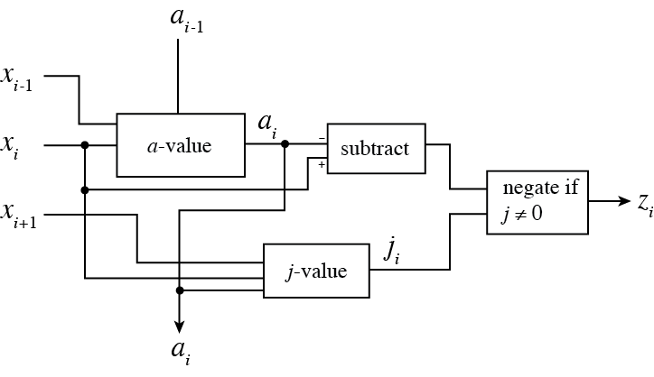
A third way of proceeding can be implemented in hardware. It shows that the nonadjacent form operation is closely comparable in cost to addition. It can be reduced to a single carry chain, and like addition, this carry chain is intrinsic to the cost.333 Algorithms for parallelized addition like [28] rely on redundant variation in the output. Since the nonadjacent form is unique, they cannot be used for this purpose.
Given an input , we can calculate the nonadjacent form via a preparing step, which generates an associated string of digits with the same length as the input. These values may be thought of as a field of assistant values , or -values. The assistant values may be found using Table II. In addition, values referred to as -values are needed, given in Table III.
Row: Column: Table value:
| 1 | 0 | ||
|---|---|---|---|
| 11 | 1 | 1 | 0 |
| 10 | 1 | 0 | |
| 1 | 0 | ||
| 01 | 1 | 0 | 0 |
| 00 | 0 | 0 | 0 |
| 0 | 0 | 0 | |
| 1 | 1 | 1 | 0 |
| 0 | 1 | 0 | |
| 0 |
Row: Column: Table value:
| 1 | 0 | ||
|---|---|---|---|
| 11 | 0 | 1 | 0 |
| 10 | 0 | 0 | 0 |
| 1 | 0 | 1 | 0 |
| 01 | 0 | 0 | 0 |
| 00 | 1 | 0 | 1 |
| 0 | 0 | 0 | 0 |
| 1 | 0 | 1 | 0 |
| 0 | 0 | 0 | 0 |
| 0 | 1 | 0 |
This approach can be reduced to a circuit with only a single carry chain, just like one operation of addition, using a repeated array of subunits as shown in Fig. 2. Intuitively, the -values produce tags that classify the modality of operation in the hand calculation of example 1. This allows a circuit to perform the entire operation in one pass (a single carry chain). A few example calculations are now given.
If , its assistant values are
and the nonadjacent form is
If , its assistant values are
the nonadjacent form is
If , the assistant values are
the nonadjacent form is
For example, if the input is
Then the assistant-values are
and
is the nonadjacent form.
III Real Nonadjacent Forms
In this section, we introduce the foundational system for the proposed floating point system in section IV. The system we introduce in this section encodes nonzero real numbers as floating point numbers, and does so in a way that is straightforward and mathematically convenient. We refer to this foundational system as the system of real nonadjacent forms. To understand this name, it can be compared to the system of complex nonadjacent forms that we introduce in section IV. The extensions in section IV rely on and inherit properties from the basic system presented here.
III-A Real Nonadjacent Forms
Consider the nonadjacent forms of two integers and , which are (momentarily) both assumed to be nonzero. We can see that, regardless of the length of and ’s nonadjacent forms, they could be stored in a ternary bit field in a recoverable way if we reverse one, say, , and place its most significant ternary bit adjacent to the most significant ternary bit of . Thus, the nonadjacent form allows for a tapered exponent without the need to specify the size of the exponent. That is, a representation of a floating point number ,
is obtained by reversing the order of the bits of the nonadjacent form of the exponent (the integer ), and concatenating these bits to the front of the nonadjacent form of the significand (the integer ), understood by convention to be lying in the range or , where is a floating point number determined by the size (commonly or ) of the ternary bit field :
where is the largest even number , hence .444 Using Theorem II.3, . In other words, the range where precision is at the highest is in a range approximately or , or . In the approach we will adopt shortly below, in this range the precision is fully .555 Note that it is quickly possible from shifting the figure in this way to obtain back-of-the-envelope estimates of precision in various ranges. For example, considering only positive values, the range where precision is at-worst will be the range where precision is at-worst will be A general way to find such ranges is also given, shortly.
For example, if , and , and we were to implement this system using decimal digits, we would write , and we would interpret this as the value . If we now take two example integers in nonadjacent form, say, and , we write , and interpret this to be the value (in signed radix 2) , or in decimal, . We can see that from the bit field , we can recover the value, regardless of the number of significant digits in and . Thus we have the basis of a tapered floating point system, up to the point when either or is 0, which we will consider shortly, but first, we can also see that the unique position where two nonzero values appear, is either , , , or depending on the signs of the exponent and the significand. Thus, these bits are working as efficiently as possible to encode useful information, including the sign. So there is no need for a hidden bit, or a sign bit, and the respective subfields of the field (exponent and significand) can be recovered and passed as-is to units equipped to compute in nonadjacent signed radix 2, also known as the canonical recoding. As we see from the comparisons in section IV, there is no need for a regime or level-index field that would enhance dynamic range. In this encoding, round-ties-to-even is implemented by simple truncation.
Next, we establish conventions for handling values at the extremities where either or is zero. The approach that we adopt is motivated as follows. For simplicity of notation, let denote the size of . We wish to preserve the invariant relation
| (16) |
for establishing a basis for working with the precision numerically. To keep this invariant, we proceed as follows. Consider , the same as before, but allowing or to be zero. We adopt the conventions that:
-
1.
If the exponent is zero, the exponent integer is encoded as an empty field.
-
2.
The largest size that the exponent may have is , one minus the size of the ternary bit field.
This pair of rules determines how we interpret a ternary bit field that has no pair of adjacent nonzero ternary bits: we interpret it as a pure significand, namely , interpreted as a value lying in the ranges , as before. To summarize, the value of the representation is obtained by first using the rules above to extract integers and from the bitfield. Then the value, as a function of and , is
| (17) |
To summarize a handful of basic properties, we have:
Theorem III.1.
Each exactly expressible real number has a unique representation in the given encoding. If is exactly expressible, its additive inverse is also exactly expressible. If is also a power of two, then its multiplicative inverse is also exactly expressible.666 This property is also shared by the Posit system, but not by the IEEE-754 system [29]. For , the exponent is given as a function of by the formula
| (18) |
Moreover, the unit-in-the-last-place is given as a function of nonzero real value as
| (19) |
The equation for the is convenient. Using it the Sterbenz lemma can be verified.
From the invariant relation Eq. 16, we have:
Theorem III.2.
For a real number , and choice of input size , let
| (20) |
Then the precision in which is represented in the proposed system is exactly , and is within the expressible range of the system (i.e., the dynamic range) if and only if .
From Theorem III.2 we can consider precision as an elementary function of the value . Since it may aid the reader’s sense of balance in the freshly proposed system, a toy example system is explicitly enumerated in Fig. 3. Encodings appear on the left, and corresponding values appear on the right. Horizontal bars indicate where an ulp shift occurs.
|
|
The reader may also wish to verify that the system for has six exactly expressible values (excluding zero): one, two, , and their negatives.
III-B Rounding
It is now possible to discuss rounding in the present system. For this, we use the precision introduced in the last section. We also let denote the largest exactly expressible value in the system, namely
Still fixing and as before, let be the rounded expression of . We can define unambiguously for all as
| (21) |
where the expression denotes the value of shifted so it lies in one of the ranges , and then truncated at the length in the canonical recoding. This routine for finding implements the round-ties-to-even rounding policy, since once the expansion in nonadjacent form of is found, rounding ties to even is performed via simple truncation.
This rounding policy is identical to that of the recently proposed Posit system. In particular, finite numbers are never rounded up or down to infinity, and nonzero numbers are never rounded to zero. However, the rounding method itself is slightly different for each system. In the Posit system, there is an exceptional case which arises when the rounded bit is not a fraction bit [29].
The IEEE-754 standard uses a different rounding policy, in particular it rounds values higher than its maximum value to infinity , as an overflow value. This is done in order to provide for a guaranteed bound on the relative error on a result whose value is . In the present system, the order of magnitude of in 32-bit single precision, for example, is over a million times larger than that of for the IEEE-754 system. So it can be considered effectively infinite for practical purposes. In other words, a calculation whose result is is already an indication that something is wrong, and it suffices to have error bounds for all other finite values, including , the penultimate representable value.
IV Extensions of the Basic System
In section III we introduced essentially a tapered floating point system, and we enumerated some of its basic properties. In this section we extend the system introduced in section III, which has underutilized the possible encodings available to its underlying ternary bitfield, to make better use of the available encoding space. We introduce a concept called a point, and use this to extend the system to incorporate complex values, and other types. The underlying point concept is analogous to a decimal point just like that of schoolhouse mathematics. Thus, the system is simple, and convenient to implement and maintain.
IV-A Points and Real Nonadjacent Forms
In this section, we make the only (very small) breaking change in the family of encodings that we discuss here. For the convenience of the reader, we distinguish the breaking change within the nomenclature. From this section on, the real nonadjacent forms will refer to the encoding we present here, not that of section III, which is referred to as the pure real nonadjacent forms, or something to that effect. When studying the properties of the proposed system as a pure floating point system, it is sometimes convenient to just work with the pure real nonadjacent forms of section III, while an implementation using the real nonadjacent forms, introduced now, will benefit from enhanced extendability, as we see shortly.
The reason for the breaking change is that the proposed extensions will all be based on one new notion, that of a point. Given a ternary field , a point is defined to be a contiguous subfield, of length 2 or greater, in which no zeros appear, and which is bounded on both the left and right either by a zero, or by the left or right boundary of the bit field. For example, the fields and each contain one point, and the field contains three points. We should already have some intuition for this notion, from our previous work in section III.
Every ternary-bit field has a well-defined positive or zero number of points, according to this definition. It is clear that any integer expressed in nonadjacent form (section II) has zero points. We can also see that most (but not all) pure real forms (section III) have exactly one point. However, the case when the exponent is zero is another case where the number of points drops again to zero. So in that case, the field becomes indistinguishable from an integer in nonadjacent form.
We would like to correct this: we would like for all the pure real forms to have exactly one point. The purpose of this is not to make room for the integers in nonadjacent form—although that is a side effect. Rather, the purpose is to be able to install a valuable convention, namely, if there are exactly two points found in the expression, then by convention, the field is cut exactly into two equal parts, and those parts are regarded separately as fields having one point each. This convention may be implemented recursively777 As a part of this recursion, it will always be assumed that the points divide evenly among the subfields, once the field is divided. Otherwise, the field has no assigned meaning. We reserve the right to make this assumption from now on, without necessarily commenting about it explicitly. as we explore further in section IV-D.
We can do this if we add a small map to the specification of the pure real system. Namely, we remap the second and third most significant ternary bit of the significand to a different bit-level form. The specification is as follows. Let be a bitfield representing a floating point number with exponent zero in the pure real form of section III. Then this class of is precisely that of the pure real forms having zero points. For convenience, suppose (without loss of generality) that represents a positive real number . Write
where denotes the ternary bits in the second and third most significant places, so that this 1 that appears is the most significant digit. We can see that has the form , where is an arbitrary ternary bit, either , or . We can therefore map the field one-to-one to a corresponding field , as in:
This creates a single point in the bitfield , as desired. We call this the point correction mapping. See Table IV.
There is an unused/reserved case, when or We call these remaining cases point-escaped values. We define two such values, plus infinity () and minus infinity (). Each of these are identified by the local bits alone, using the properties:
-
•
positive infinity (), : the field has one point, and starts on the left with the bit pattern .
-
•
negative infinity (), : the field has one point, and starts on the left with the bit pattern .
A glaring special case, that we have put off until now, is the value zero. It is possible to use a point-escaped field to define the value zero. However, in order to avoid introducing another exceptional value to the system, we prefer that the encoding for the value zero is the field of zeros, the same encoding as in the nonadjacent integer system. This makes sense, because a representation of zero in a floating point system is a symbolic entity (not a numerical one), and the system of integers is a field of symbolic entities which already contains a symbolic zero.
Thus, the system shares in common with the IEEE-754 system and the Posit system the property that zero (or more precisely , in the IEEE-754 case) is encoded with the field of zeros.
The point-escaped values are defined for symbolic purposes (for example, division of a nonzero floating point number by symbolic zero) as symblic infinities can arise in useful (symbolic) results in many contexts. It is suggested, then, to regard in the nonadjacent system as numerical infinite values, while in the nonadjacent system can be regarded as symbolic infinite values.
This completely describes the system of real nonadjacent forms, which are also understood to contain the representations of integers in their nonadjacent forms.
IV-B Boolean Forms
Before we go further, we note that the system can be regarded as containing a further extension, to boolean forms. Namely, we can map the value 1 to the boolean value true. and to the boolean value false. Then ternary bit fields in which no zero appears can be interpreted as boolean fields, which are distinguishable from all of the real nonadjacent forms of section IV-A.
In particular, the field of all ones may be read as true, boolean true, and the field of all may be read as false, boolean false.
IV-C Complex Nonadjacent Forms
Just above, we introduced the notion of a point. We noted that every ternary bit field has a positive or zero number of points. We modified the system of section III slightly, so that each encoded tapered floating point representation, including exceptional values, has at most one point, out of the possible range of points (points with length 2), (points with length 3), and also points of length 4, however points of length 3 or 4 are only possible if they are on the leftmost side of the bit field. As we noted, this allows us to represent integers, boolean fields, and real numbers in the same system. However, we have not come close to exhausting the possible encodings. Now, we wish to go further and provide an encoding for complex numbers.
To encode the complex numbers, we utilize the case when the bit field contains two points, in such a way that when the field is divided down the middle into equal subfields, each subfield has exactly one point. We associate to the left subfield a floating point number whose value is , and the right subfield a floating point number whose value is , and we interpret the full ternary bit field as representing the quantity , where is the complex unit .
This describes the extension, up to what is done when either or is or , or when either or is zero. For the infinite cases, we handle these by the rule:
-
1.
If a field contains exactly two points and begins with the pattern , then it represents the value complex infinity, denoted .
Next to consider is the zero cases. First, notice that if we try, in the naïve way, to represent either or in the encoding scheme proposed shortly above (in which we divide the field into two equal subfields), and use the encoding of zero established in the preceding section, we obtain a bit field with only one point, not two points, meaning that it is indistinguishable from a real nonadjacent form. We also make note of the possibility that a real nonadjacent form can be represented in two ways, either as real , or complex , each with a different precision, which threatens to add a clutter of case-switching to the resulting system. We can therefore consider the possibility of making the complex numbers a true extension of the preceding encoding, and thereby avoid such clutter to unburden potential hardware implementations.
To do this, we now wish to introduce another type of point. The points defined in section IV-A are now Type I points, and we now wish to define Type II points. To do this, we introduce a generalization of the point correction mapping. Instead of a single point correction mapping, we now have a family of five them, labeled PCM1, PCM2, PCM3, PCM4, and PCM5. The PCM1 mapping is the original point correction mapping in Table IV, associated with Type I points.
We do not fully specify the PCM2, PCM3, PCM4, or PCM5 mappings at the bit level here, as it may be technology-dependent and is not really relevant here. However, we can provide a sketch of them. The PCM2 mapping is as follows: given a point of length 2 somewhere in the middle of the bit field, as in
we modify the point by changing the right zero to a nonzero digit :
This gives a point of length either 3 or 4. The PCM3 mapping changes a point of length 2 positioned at the left of the bit field, as in:
to a point of length either 5 or 6 by mapping the pattern to a pattern with no zeros:
There are still two more, PCM4, and PCM5. PCM4 is similar to PCM3, except it takes a point of length 2 positioned at the right of the bit field, as in:
and maps it to a point of length either 5 or 6, as in:
Finally, PCM5 takes a bit field with no point (encoding a real number with the maximum precision), as in
and replaces the pattern with nonzero digits , as in:
giving a point of length either 7 or 8.
We can now see that we are able to recognize what PCM mapping to apply, based on
-
1.
whether a point is adjacent to the left of the bitfield (case L), adjacent to the right of the bitfield (case R), or otherwise (case M),
-
2.
the length of the point, either 2, 3, 4, 5, 6, 7, or 8.
We briefly call this information the point class. The point class provides us with the ability to recover the original point, and to derive the point type. This information is summarized in Fig. 4. In the figure, PCM0 denotes no modification to the point.
| visual aid | point class | point type | PCM | ||||||
|---|---|---|---|---|---|---|---|---|---|
|
|
|
I | PCM0 | ||||||
| L3, L4 | I | PCM1 | |||||||
|
II | PCM2 | |||||||
| L5, L6 | II | PCM3 | |||||||
| R5, R6 | II | PCM4 | |||||||
| L7, L8 | II | PCM5 |
Now we can return to the complex number encoding. Equipped with two types of point, we proceed by cases given a complex number :
-
1.
If is pure real, it is encoded as a real number using a type I point.
-
2.
If is pure imaginary, it is encoded as a real number using a type II point. (Note the agreement when is both pure real, and pure imaginary.)
-
3.
Otherwise, for two nonzero and . These real numbers and are encoded as real nonadjacent forms in the size , and encoded together in concatenated form, using a type I point for and a type II point for , in a bit field of size .888 It is a choice to use a type II point for . It may be amenable to further generalizations to proceed this way.
This provides for an extended number system that we call the complex nonadjacent forms. This system contains the real nonadjacent forms as a precise, one-to-one subset. This system preserves the property of the real nonadjacent forms, that there is only one way to represent zero (as the field of zeros), regardless of whether it is complex, real, or an integer. It contains three exceptional values: and the complex point at infinity (projective infinity) .
IV-D Point Types and Point Signature
In fact, the utilization of the system is still far below the maximum. To make further use of the unused encoding space, we can make further use of point-escaped values. We can also make further use of point types. It is easy to do this, in fact (at the level of specification), if we consolidate this additional structure with the notion of a point signature.
If we scan a ternary bit-field from left to right, we can make a list of the points that we observe. By convention, we write this list in the form , where each variable denotes an integer that expresses what type of point is observed (either type I or type II), and is the number of points observed, or if no points are observed. Note that we also say that a full point is a point that has the full length of the bit field. The following scheme includes all exceptional cases:
-
1.
: a type I point is detected.
-
2.
: a type II point is detected.
-
3.
: a full point is detected.
-
4.
, no point is detected, and the field is not all zeros.
-
5.
, the field is all zeros.
The resulting point signature is a succinct way to express extensions to the basic system of real and complex nonadjacent forms.
With this, we can succinctly recapitulate all the material of this section:
-
1.
If the field has a point signature , we consider it to be a boolean.
-
2.
If the field has a point signature or , we consider it to be an integer.
-
3.
If the field has a point signature or , we consider it to be an extended real number: either a finite real number, , or .
-
4.
If the field has a point signature , , , or , the field is considered to be a complex number, or else complex infinity .
Other than the exceptional field of only zeros, which is regarded as simultaneously a real, an integer, and a complex number, and the signature which is either real or complex depending only on the context, the classification is a division of the possibilities into distinct classes.
IV-E Vector Nonadjacent Forms
We can use point signatures to define further extensions of the system for vector forms. If the field has a point signature , the field may be considered to be a two-vector, that is, a pair of reals. We can also reserve the case of point signature for four-vectors.999 As in the previously encountered cases, there is no assigned meaning unless the bitfield can be divided in half in such a way that the point signatures divide evenly. For example, dividing a bit field with point signature in half must give two bit fields with point signature and these in turn must both divide into two equally-sized bit fields with point signature . A further unused case is , which might be considered as a foundation for complex two-vectors. A further possibility is to encode higher number fields, such as quaternions and octonions, by making use of unused point signatures. One possibility is to use the signature as a foundation for a quaternion encoding.
In raising the possibility of these extensions, no mention has been made about exceptional cases, including zero cases. We do not delve further into possible ways of handling these exceptions here, as the proposed extensions are not well tested at the present time, and are only offered on a preliminary basis, along with a call for comments.
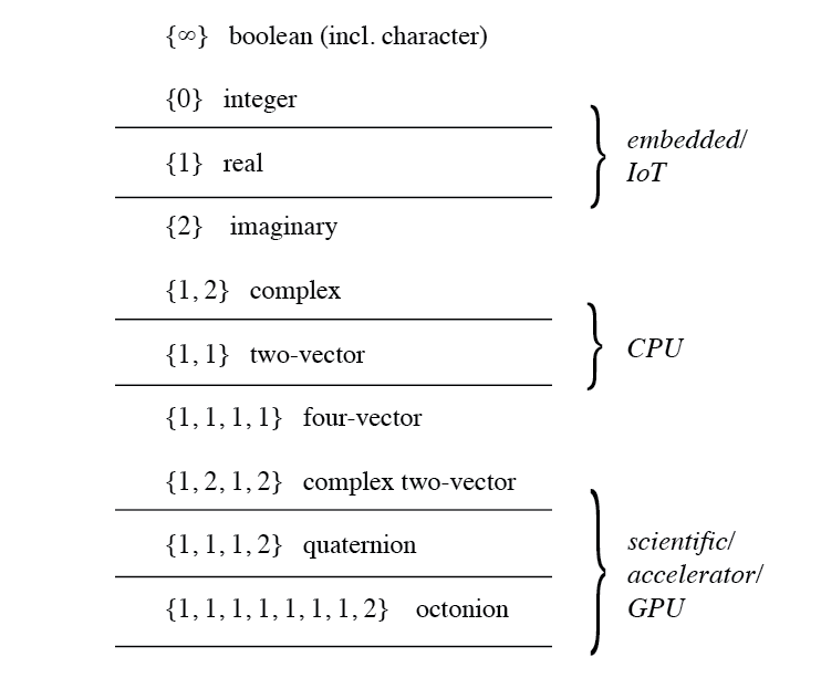
We give a summary of the point signatures in the proposed system in Fig. 5, where the zero case is omitted for clarity. In the figure, the vertical lines indicate divisions where implementations might stop providing hardware support, along with a suggested hardware class in each case, among embedded/IoT devices, CPU class devices, and scientific/accelerator devices, including GPUs.
IV-F Instruction Types
The proposed system exhibits a form of hardware type safety, namely, various mathematical objects (booleans, integers, real and complex numbers, etc.) are represented in a common encoding. We now make brief mention of the possible implications of this property.
Considering that character encodings can all be assimilated into the boolean category, the potential arises for a firm, system-wide line between code and data, which could be drawn via the further use of the point signature notion (and possibly, further use of point correction mappings to encompass further point types). Using only this technique, it would be possible to encode machine instructions in a such a way that their machine and memory representations are always immediately distinguishable from data, which would eliminate a range of security attacks. Support for this feature would have to encompass controls on the ISA (instruction set architecture, including the machine instruction set), whereby operations would be required to be closed operations on the data types, simply so that it is impossible to transform data into machine instructions that could be run to malicious ends. For example, it would be harmless to allow boolean operations on boolean types, as long as via such operations, it is not possible to transform boolean types into other types (real numbers, integers, machine instruction types). This implies that, if such a feature is targeted, the full family of ternary operations that would be present at the hardware/circuit level would not be exposed at the level of the ISA/architecture. This is perhaps reason for some relief, as the number of ternary boolean operations numbers well into the thousands.101010 There are nondegenerate ternary-valued functions of two ternary inputs. Of these, there are commutative functions, and noncommutative functions.
V Comparisons With Morris, IEEE-754, and Posit Systems
In this section we compare the proposed system to other systems that have been proposed. We consider three systems: the original tapered system due to Morris [7], the IEEE-754-1985/2008 system [13, 14], and the recently proposed Posit system [4, 12].
Throughout this section denotes a nonzero real number. For each system, we will consider the precision of the corresponding representation as a function of the exponent in base 2 of a represented value , or the precision by order of magnitude (PBOM). Note that PBOM factor considers order of magnitudes in base 2, not in base 10, as is common in many fields. We denote this factor briefly by , or . We denote the base-2 order of magnitude of a represented value by :
So we can write as as it is a function of the order of magnitude of represented value .
V-A Overview
In this section, we summarize in condensed form some of the most salient features of each floating point encoding system.
V-A1 Fractional part encoding scheme
The Morris system, the IEEE-754 system, and the Posit system all utilize a hidden bit and a sign bit for the significand/fraction. The proposed nonadjacent system instead stores all of the value’s sign information in the point.
V-A2 Exponent encoding scheme
For the exponent, the Morris system uses sign-magnitude encoding. The IEEE-754 system uses a concept called bias that is related to subnormals: the bias value is where the subnormal exponent range will start. The Posit system uses a mixed-base encoding, one subfield using signed base-1, and the remainder using unsigned base-2.
V-A3 Tapering
All of the systems use some form of tapering. IEEE-754 uses a fixed-size exponent in the normal range, while in the subnormal range (around zero), the precision tapers off and contributes instead to the exponent (in base-1 fashion), to allow for gradual underflow. The Morris and Posit systems use a tapered exponent (variable size exponent), and so does the proposed nonadjacent system, but each system utilizes its own distinct mechanism to achieve the characteristic tapering effect.
V-A4 Exponent
The Morris system uses a fixed-size subfield to represent the tapered exponent length. The choice of the size of is arbitrary and must be chosen by the designer. Guidance for choosing was not implemented by Morris. The IEEE-754 system uses a fixed-size exponent field, which has well-known advantages for hardware. The choice of the size of the exponent field is arbitrary and could be chosen by the designer, but the standard has well-established guidelines on the choice for standard input sizes. The Posit system uses a fixed-size subfield for part of the exponent, however, it uses a built-in convention that allows the subfield to be arbitrarily truncated on the right. The choice of the size of this subfield is arbitrary and must be chosen by the designer, but the Posit system proposal [12] establishes recommended/standard values of for the standard input sizes. The Posit system uses a base-1 field to encode the major contribution in the exponent (the regime).
V-A5 Rounding
The Morris system gives no recommendations/suggestions for rounding policy. The IEEE-754 standard provides four rounding conventions: round-up, round-down, round-to-zero, and round-ties-to-even, with round-ties-to-even as the default policy. For values greater than the dynamic range, it rounds to . Posits use round-ties-to-even only, and never rounds non-representable values to zero or infinity.
V-A6 Exceptions
The Morris system specifies no exceptional values. The IEEE-754 system has several well-known exceptional values, including NaN (with payload), , and . The Posit system defines two exceptional values, 0 and a value NaR, which englobes all infinite and undefined quantities.
Next, we will provide a description of each of the systems, and supply the PBOM factors for the Posit system and the IEEE system.
V-B Morris Tapered Numbers
The proposed number system of Morris [7] is the earliest proposal of a tapered number system for use in computing machines. Its characteristic feature is a fixed length subfield of size where is a maximum value , which presents a figure as an unsigned binary integer. Then, it provides for two variable-length fields that present two unsigned integers and , with the size of the field for being always exactly . Finally, it has two reserved bits for the signs and of and , respectively, so that and are essentially quantities encoded in sign-magnitude, as in the illustration:
![[Uncaptioned image]](/html/2105.14401/assets/img/144ppi/morrisfield003.png) |
From this the maximum value of is the largest value to satisfy
| (22) |
No bias is considered, and the encoded value is defined as follows:
| (23) |
where the convention is . The dynamic range is then
| (24) |
Morris suggests . Morris considers , having in mind the IBM 7090 mainframe computer which uses a fixed 7 bits for the exponent and 27 bits for the fraction, plus two sign bits. In the Morris system many values are encoded redundantly in multiple different ways, but as noted by Morris, this can be avoided if the size of the field for , the order of magnitude of represented value , is taken to be the size of when . In that case, the precision is
| (25) |
but the case of exponent zero () is exceptional. In this system, the maximum dynamic range can be considerably larger than for a fixed-point system, at the cost of precision across the entire dynamic range. We do not study the precision by order of magnitude (PBOM) for the Morris system here, but if we did, the curve would have a shape like that of the nonadjacent system. This is because the Morris system, like the nonadjacent system, encodes the exponent in base-2 fashion.
V-C IEEE-754
The IEEE-754-1985 Standard for Floating Point Arithmetic (ANSI/IEEE Std 754-1985) was introduced in 1985 [13] and revised in 2008 [14]. We focus here only on the binary encodings for standard input sizes provided by the standard. It is possible, in a non-standard way, to interpret the IEEE-754 system as a single floating point system derived from an input size . See Table V, which uses the convenient value of the exponent field size . The formula
| (26) |
happens to fit the IEEE-754 specification for the standard input sizes () although it is not a part of the standard.
| name, (informal name) | |||
| 8 | 5 | 3 | - |
| 16 | 11 | 15 | binary16 (half precision) |
| 32 | 23 | 127 | binary32 (single precision) |
| 64 | 52 | 1023 | binary64 (double precision) |
| 128 | 112 | 16383 | binary128 (quad precision) |
| ⋮ | ⋮ | ⋮ | |
From the input field we extract three unsigned integers and as subfields from left to right. For fixed , each subfield has a fixed size 1, , and , respectively, as in the illustration:
![[Uncaptioned image]](/html/2105.14401/assets/img/144ppi/ieee754field004.png) |
The value is then
| (27) |
Theorem V.1.
The precision by order of magnitude (PBOM) for the IEEE-754 system is given by the rule
| (28) |
V-D Posit System
The Posit system is a component of Gustafson’s comprehensive Unum program [30, 31]. It is designed as a one-to-one replacement for IEEE-754 floating point numbers. The Posit system forms a chapter in the recent revival of research into tapered number systems [32]. In the Posit system, the exponent field size parameter also appears, although in a different guise: now it only encodes the exponent to within a given regime of the dynamic range. In this setting, it is denoted . The following formula for from [29] is recommended for the Posit system [12] for standard input sizes.
| (29) |
This gives the values : 1, 2, 3, 4 for the standard input sizes and for the ultra-low precision input size . Other choices for are possible, but we do not consider other values here. Roughly speaking, the choice of is a trade-off between precision and dynamic range.
A binary bit field of input size may be read from left to right as a posit number as follows. The first bit is a sign bit . The next run following is interpreted as a redundant-signed base-1 integer. That is, the length of the run after the sign bit’s length presents a figure , and the “sign” of the run (whether it is a run of ones, 1, or a run of zeros, 0) presents another figure . After this, the bit which terminates the run (if any) is thrown away; we refer to this bit as the stop bit although this nomenclature is not part of the standard. It is possible that there is no stop bit. In this case, . In that case if , it is exceptional, otherwise it is treated normally, which explains the one appearing in the second branch in the definition of below. (It also supplies the possibility .) From these, the figure , ranging from to , is obtained:
| (30) |
The value might be called the positivity, but this is not part of the standard. The remainder of the bits is read in one of two ways: if there is strictly more than bits, it is divided into two parts: the first part has length and the second part has length . The first part presents a figure as an unsigned integer, and the second part presents a figure , also an unsigned integer.
If there are exactly bits or fewer than bits (in this case the value is in the extremities of the dynamic range), all of the bits are used to present a figure as an unsigned integer of length , but if there are fewer than bits available, the figure is obtained by right-padding with zeros, as needed. Finally, may be taken to be zero.
Thus the encoding presents the figures and , as in the illustration:
![[Uncaptioned image]](/html/2105.14401/assets/img/144ppi/positfield002.png) |
From this the value is
| (31) |
where we take . We can see that the exponent in the Posit system may be broken into a regime whose size is determined by and which is indexed by , while is an offset within the regime. There are always exactly regimes, but some regimes at the extremities are “clipped” in the sense that there is less than the full range of the offset value. It is not difficult to see from this description that the Posit system provides a unique code for real numbers, and one exceptional code, NaR. It exhaustively uses up the possible bit fields for the given input size.
Also note that due to the branch in the definition of , there is a small asymmetry in the nominal precision between the case when and when , when and are compared. However, because the sign of in Eq. 31 is unaffected by this, the ranges where precisions are equal overlap only up to their endpoints. In other words, if is considered, precision is equal in two counterpart intervals, very nearly symmetric around , namely where is in the half-open interval and the counterpart interval where the regime is in fact not but rather . For example, precision is at the maximum precision level in the regime , corresponding to in the interval . It is also at the maximum precision in its counterpart regime , corresponding to in the interval , or in other words, in the half-open interval .
We have the following.
Theorem V.2.
The precision by order of magnitude (PBOM) for the system POSIT is given by the maximum between zero, and the rule
| (32) |
where
| (33) |
Proof: See appendix A.
V-E The Nonadjacent System
We already introduced the nonadjacent system (NONADJ) in section III. We have the following re-expression of Theorem III.2 (some additional remarks are included in appendix A):
Theorem V.3.
The precision by order of magnitude (PBOM) for the system NONADJ is given by the maximum between zero, and the rule
| (34) |
V-F Comparison of Systems
In this section, we focus on the IEEE-754 system (IEEE), the Posit system (POSIT), and the newly proposed nonadjacent system, for which it suffices to consider the basic real nonadjacent system of section III (NONADJ).
A fair comparison of the newly proposed nonadjacent system and the other two systems is a significant challenge, since the underlying technology cannot be treated as an invariant of the study. One system, the nonadjacent system, relies on ternary technology, while the others rely on binary technology. In lieu of efforts towards this end, we can consider here a handful of factors of merit that may be readily derived by analytic means from the definitions of the respective systems.
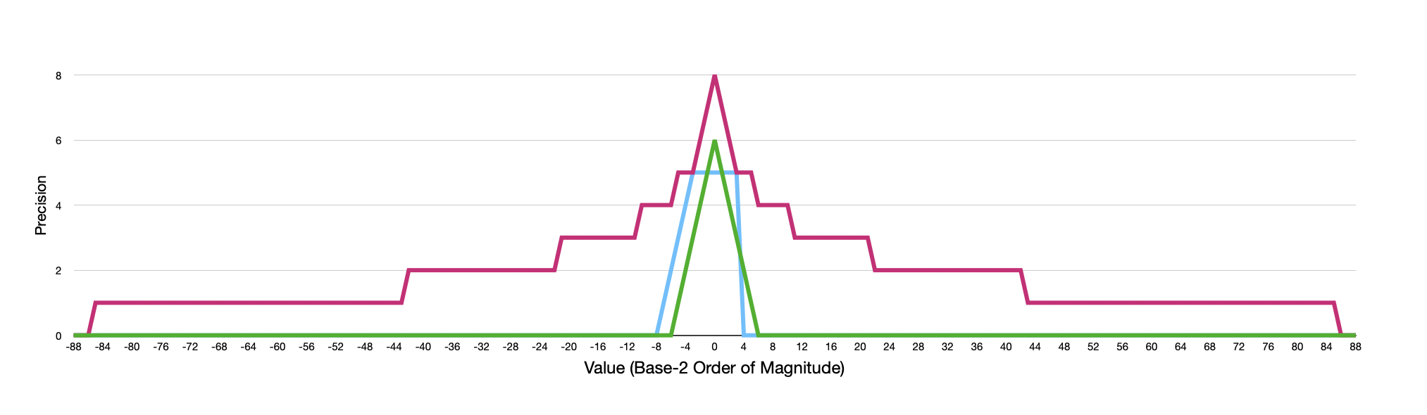
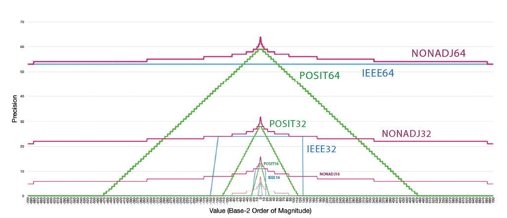
The curves for the three systems IEEE, POSIT, and NONADJ are shown for the ultra-low precision case in Fig. 6. In Fig. 7, the same curves are shown, along with the curves for the standard input sizes and .
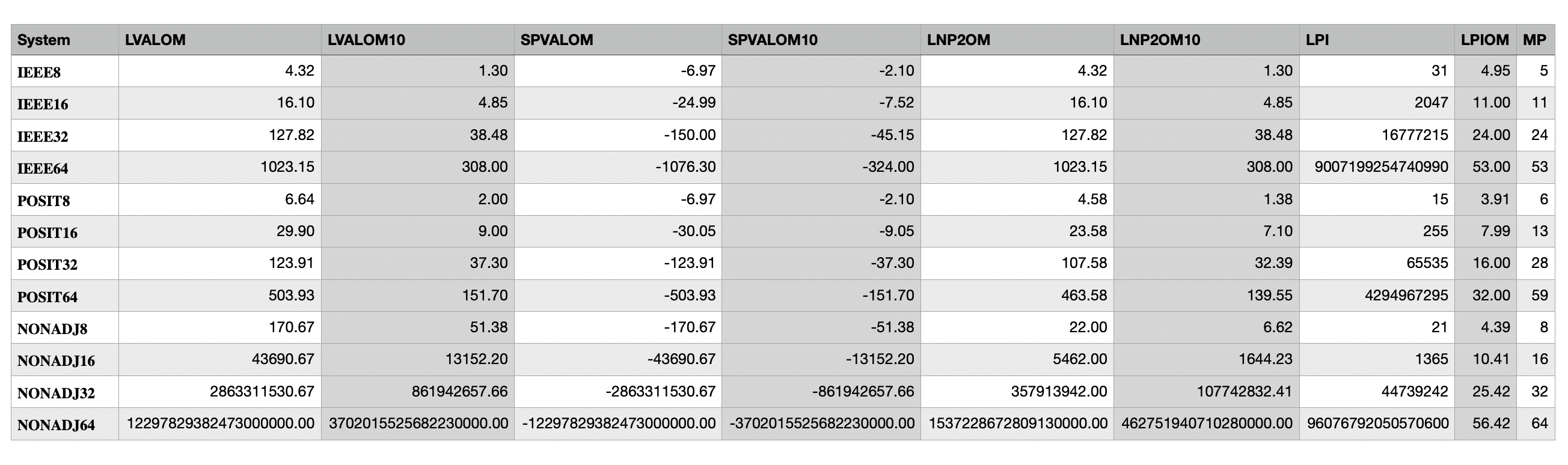
We also consider a small number of factors of merit for each system, for four input sizes 8, 16, 32, 64. See Fig. 8 for a concise summary of the values of the factors. The factors of merit that we consider for the three systems are:
-
1.
The largest value (LVAL). The largest finite real number that may be represented in the system. In Fig. 8, we include only the order of magnitude (the base-2 logarithm), LVALOM. For convenience, we also show the base-10 logarithm, LVALOM10.
-
2.
The smallest positive value (SPVAL). The smallest positive value that may be represented in the system. For IEEE-754, we can distinguish two cases, the smallest positive normal value, and the smallest positive subnormal value, while of course +0 is not considered; only the smallest subnormal value is shown in Fig. 8. SPVAL and LVAL together establish the total dynamic range. In Fig. 8, we include only the order of magnitude (the base-2 logarithm), SPVALOM. It also presents the base-10 logarithm, SPVALOM10.
-
3.
largest non-power of two (LNP2). The largest finite representable value which is not a power of two. This figure assists in evaluating the tapered systems. For both the Posit system and the proposed nonadjacent system, it indicates a prominent marker past which the dynamic range is really only very sparsely populated. In particular, for the Posit system, it also indicates precisly where clipping effect begins to occur within the regimes due to right-padding. In Fig. 8, we show the order of magnitude (the base-2 logarithm), LNP2OM. For convenience, we also show the base-10 logarithm, LNP2OM10.
-
4.
largest precise integer (LPI). The largest integer that may be represented in the system, and whose immediate predecessor integer may also be represented in the system. This figure gives an idea of the range for integer arithmetic on the FPU in the given system. The LPI and the LPI’s order of magnitude (the base-2 logarithm), LPIOM, are presented in Fig. 8.
-
5.
maximum precision (MP). The maximum precision, in binary or redundant signed binary digits, achievable in the system: precision in the system’s ideal range.
VI Conclusion
We have proposed a new encoding for floating point numbers, based on the redundant signed radix 2 number system, using the canonical recoding, also known as the nonadjacent form. This system has long been known as a valuable resource for fast computer arithmetic, and our work has explored the possibility of its use outside of that context. The redundant nature of the system is what gives it both high precision and high dynamic range, because it allows for two detectable variable-width subfields in the input field. The resulting system implements round-ties-to-even rounding policy via truncation, making unbiased rounding both fast and easy to implement. The encoding offers an interoperable range of choices suitable for potential hardware targets, from embedded, to CPU, to scientific/accelerator/GPU devices. It achieves this via an extensible system that is easy to maintain, based on the proposed concept of point and point types. The point concept is closely analogous to a decimal point, and helps to establish an extensible tapered floating point system with properties facilitating error analysis, potentially offering aid and benefit to hardware designers, scientists and mathematicians, numerical application programmers, and system developers.
The proposed system enjoys the stability and regularity properties of a tapered floating point system, including most notably gradual underflow and overflow. Unlike the binary encodings for tapered systems that were reviewed, and those known to the author, the present system encodes the exponent and significand in a directly recoverable way, offsetting the cost to hardware of finding the variably-located point. The exponenent and significand are encoded in a base higher than 1, as in the Morris system, but unlike in the Morris system, there are no bits wasted or reserved in any part of the input dynamic range. As a result, the system exhibits both a high dynamic range and generally high level of precision. In fact, as we noted, the system exceeds both the IEEE-754 and the Posit system in dynamic range is equal or better in precision throughout its entire dynamic range, and offers higher maximum precision in its ideal range. The encoding system shares with the Posit system the property that comparison is achieved by bitwise comparison, with the exception of the exceptional values .
We also saw that the proposed encoding merges into one system all of the various encodings for the basic number and logic types which are of importance in practice, in a robust and type-safe way: boolean fields (including boolean true and boolean false which are distinguished from numerical 1 and numerical 0, and thereby potentially machine addresses), integers, and real values as floating point. We note that, for example, both the integer system and floating point system share a common zero, namely, the field of only zeros, which is the unique way of encoding the number zero. All other integers are either uniquely representable as integers (if very large), or else have exactly two representations in the system, one as floating point, and one as integer. All other floating point numbers have a single unique representation, with no exceptional corrective ranges like the subnormal range of IEEE-754. Analytic formulas are readily available for the encoding’s precision and exponent, given any input real value and these do not contain any arbitrary constants. In addition, the range of representable integers in the proposed integer encoding mirrors closely but slightly exceeds the range of the two’s complement system, when comparing equal input sizes.
The proposed system, however, can also go beyond integers and real numbers, and provide support for complex numbers, two-vectors, and (if the hardware chooses) four-vectors and quaternions. In a straightforward and evident manner, it could be extended still further to support eight-vectors and octonions (for advanced scientific applications) while still maintaining perfect interoperability with lower-level encodings. The system’s integration with these structures offers potential for intelligent and robust support for mathematical operations, including inverse operations like the square root and complex roots in general, and simple solvers, as well as elementary functions and numbers to a power (which can be complex, in general). This makes the full system a candidate for applications where robust, stable numerical processing is needed, including scientific computing, signal processing, computer graphics, and machine learning.
For machine learning the system offers some particular advantages. First, during training regularization is used to keep weights bounded to a range near the values 1 and . As noted, this is precisely where the tapered precision is at its maximum, namely the full input size . This offers the opportunity to save hardware area by decreasing the total size of stored values. If computation can be expected to remain in this range, or be in the range with some reasonable precision near zero, the computation can be carried out with a precision low enough to allow the hardware to be implemented in very low-area, low-energy environments, such as embedded/IoT applications, and for AI on the Edge. Further study of this question is warranted for such ultra-low precision applications.
The use of nonadjacent forms thus offers computational advantages which offset the resource underutilization that nonadjacent nonzero bits will generate. Evaluation of this trade-off in terms of real physical space and time (area and delay, in the language of circuits) awaits technology on which such estimates could be based. It is an open question whether a ternary logic technology exists which makes the proposed system comparable by metrics such as area, energy/power, cost, and delay, with pure binary encodings. The ternary technology that the proposed system relies on can be implemented in a Field-Programmable Gate Array or other programmable hardware, but it requires doubling the input width size to account for binary-to-ternary encodings. To the best of our knowledge, true ternary technology is not currently supported by technology vendors or technology development platforms.
Appendix A Appendix A
Proof:
Let the width of an integer in nonadjacent form be . For the proof we can assume that . When we add the values as grows, we have a geometric series, however, the term separates into two cases depending on the parity of . The following formulas result, which give the value of the maximal number (measured by value) in each batch of numbers having width . In other words, it is the value of the last integer with the given width .
| (35) |
If we add one to each of these, we obtain formulas for the minimal numbers (measured by value) in each batch of numbers of digits, for some , and these are symmetric with the last numbers:
| (36) |
Now we claim that, for all integers ,
| (37) |
We can first invert the equations in 36 to give the (exact) width of the minimal number (by value) in each batch given its value . Calling this value , we have two rules from the two expressions in equation 36, namely,
| (38) | ||||
| (39) |
By definition, the expression returns an integer for every input which is a minimal number for some even number of digits. Therefore, for every such integer (where the number of digits in the system grows by 1), that value is the width . The floor of that expression also provides the value for the maximum value of a batch of odd-sized digits, because increases strictly.
On the other hand, as the values transition from an even width batch to an odd-width batch, the value passes an exact integer value, see Fig. 9. Since , this proves the claim holds for all values of . To establish formula (1), observe that
Formula (2) then follows immediately, since for integers , the expression is never an integer since divides . ∎
| 2 | 1.321928 | 1 | 1.584962 |
|---|---|---|---|
| 3 | 2 | 1.807354 | 2.169925 |
| 4 | 2.459431 | 2.321928 | 2.584962 |
| 5 | 2.807354 | 2.700439 | 2.906890 |
| 6 | 3.087462 | 3 | 3.169925 |
| 7 | 3.321928 | 3.247927 | 3.392317 |
| 8 | 3.523561 | 3.459431 | 3.584962 |
| 9 | 3.700439 | 3.643856 | 3.754887 |
| 10 | 3.857980 | 3.807354 | 3.906890 |
| 11 | 4 | 3.954196 | 4.044394 |
| 12 | 4.129283 | 4.087462 | 4.169925 |
| 13 | 4.247927 | 4.209453 | 4.285402 |
Proof:
The following proof appears in [33]. First observe from the initial part of the sequence of positive integers in nonadjacent form,
that there is precisely one integer with width 0, and precisely one integer having width 1. Now let have width . Suppose that ends in the digit . In that case, the representation consists of a valid representation of width concatenated with . Now suppose that it ends with a or a . Then the representation of consists of a valid representation of width concatenated with either or . Therefore, if is the number of integers with width will satisfy
for . The resulting integer sequence has the closed form given in Eq. LABEL:e.jacobsthal. ∎
Proof:
For the system POSIT, the regime value is the value right-shifted. We can write
and
Then
and then from arithmetic on the bit field,
Collecting these together gives Eq. 32, as desired. ∎
References
- [1] R. Schwartz, J. Dodge, N. A. Smith, and O. Etzioni, “Green AI,” arXiv preprint arXiv:1907.10597v3, July 2019.
- [2] J. Do, V. C. Ferreira, H. Bobarshad, M. Torabzadehkashi, S. Rezaei, A. Heydarigorji, D. Souza, B. F. Goldstein, L. Santiago, M. S. Kim, P. M. V. Lima, F. M. G. França, and V. Alves, “Cost-effective, energy-efficient, and scalable storage computing for large-scale ai applications,” ACM Trans. Storage, vol. 16, no. 4, November 2020.
- [3] D. Hoang, P. Klacansky, H. Bhatia, P.-T. Bremer, P. Lindstrom, and V. Pascucci, “A study of the trade-off between reducing precision and reducing resolution for data analysis and visualization,” IEEE Transactions on Visualization and Computer Graphics, vol. 25, no. 1, pp. 1193–1203, 2019.
- [4] J. L. Gustafson and I. T. Yonemoto, “Beating floating point at its own game: Posit arithmetic,” Supercomputing Frontiers and Innovations, vol. 4, no. 2, pp. 71–86, 2017.
- [5] P. Lindstrom, S. Lloyd, and J. Hittinger, “Universal Coding of the Reals: Alternatives to IEEE Floating Point,” ACM Proceedings of the Conference for Next Generation Arithmetic (CoNGA ’18), 2018.
- [6] P. Lindstrom, “Variable-Radix Coding of the Reals,” 2020 IEEE 27th Symposium on Computer Arithmetic (ARITH), 2020.
- [7] R. Morris, “Tapered floating point: A new floating-point representation,” IEEE Transactions on Computers, vol. C-20, no. 12, pp. 1578–1579, 1971.
- [8] H. Hamada, “URR: Universal representation of real numbers,” New Generation Comput., vol. 1, pp. 205–209, 1983.
- [9] H. Yokoo, “Overflow/Underflow-Free Floating-Point Number Representations with Self-Delimiting Variable-Length Exponent Field,” IEEE Transactions on Computers, vol. 41, no. 8, pp. 1033–1039, 1992.
- [10] I. Hubara, M. Courbariaux, D. Soudry, R. El-Yaniv, and Y. Bengio, “Quantized neural networks: Training neural networks with low precision weights and activations,” Journal of Machine Learning Research, 2018.
- [11] A. Capotondi, M. Rusci, M. Fariselli, and L. Benini, “Cmix-nn: Mixed low-precision cnn library for memory-constrained edge devices,” IEEE Transactions on Circuits and Systems II: Express Briefs, vol. 67, no. 5, pp. 871–875, 2020.
- [12] The Posit Working Group, “Posit standard documentation,” Release 3.2-draft, 2018.
- [13] American National Standards Institute and Institute of Electrical and Electronic Engineers, “IEEE standard for binary floating-point arithmetic,” ANSI/IEEE Standard 754-1985, 1985.
- [14] IEEE Computer Society, “IEEE standard for Floating-Point Arithmetic,” IEEE Standard 754-2008, August 2008.
- [15] Z. Carmichael, H. F. Langroudi, C. Khazanov, J. Lillie, J. L. Gustafson, and D. Kudithipudi, “Deep positron: A deep neural network using the posit number system,” 2019 Design, Automation Test in Europe Conference Exhibition (DATE), pp. 1421–1426, 2019.
- [16] J. Lu, C. Fang, M. Xu, J. Lin, and Z. Wang, “Evaluations on deep neural networks training using posit number system,” IEEE Transactions on Computers, vol. 70, no. 2, pp. 174–187, 2021.
- [17] N. Buoncristiani, S. Shah, D. Donofrio, and J. Shalf, “Evaluating the numerical stability of posit arithmetic,” 2020 IEEE International Parallel and Distributed Processing Symposium (IPDPS), pp. 612–621, 2020.
- [18] M. Klöwer, P. D. Düben, and T. N. Palmer, “Posits as an alternative to floats for weather and climate models,” in Conference for Next Generation Arithmetic, 2019.
- [19] Y. Uguen, L. Forget, and F. de Dinechin, “Evaluating the hardware cost of the posit number system,” 2019 29th International Conference on Field Programmable Logic and Applications (FPL), pp. 106–113, 2019.
- [20] S. H. Fatemi Langroudi, T. Pandit, and D. Kudithipudi, “Deep learning inference on embedded devices: Fixed-point vs posit,” 2018 1st Workshop on Energy Efficient Machine Learning and Cognitive Computing for Embedded Applications (EMC2), pp. 19–23, 2018.
- [21] A. D. Booth, “A signed binary multiplication technique,” Quarterly Journal of Mechanics and Applied Mathematics, vol. 4, pp. 236–240, 1951.
- [22] A.-L. Cauchy, “Sur les moyens d’aviter les erreurs dans les calculs numeriques,” Comptes rendus de l’Academie des Sciences, no. 11, 1840.
- [23] G. W. Reitwiesner, Advances in Computers. Elsevier, 1960, vol. 1, ch. Binary Arithmetic, pp. 231–308.
- [24] I. Koren, Computer Arithmetic Algorithms, 2nd ed. Natick, Massachusetts: A K Peters, 2002.
- [25] F. Morain and J. Olivos, “Speeding up the computations on an elliptic curve using addition-subtraction chains,” Informatique théorique et Applications/Theoretical Informatics and Applications, vol. 24, no. 6, pp. 531–544, 1990.
- [26] N. Koblitz, “CM-curves with good cryptographic properties,” in Advances in Cryptology, ser. LNCS, J. Feigenbaum, Ed., vol. 576. Springer-Verlag, 1992, pp. 279–287.
- [27] The OEIS Foundation. The Online Encyclopedia of Integer Sequences. [Online]. Available: https://oeis.org/
- [28] A. Avizienis, “Signed-digit number representations for fast parallel arithmetic,” IRE Transactions on Electronic Computers, vol. EC-10, pp. 389–400, September 1961.
- [29] J. L. Gustafson, “Posit arithmetic,” online: https://www.posithub.org/docs/Posits4.pdf, October 2017.
- [30] ——, The End of Error: Unum Computing, ser. Computational Science Series. Chapman-Hall/CRC Press, 2017.
- [31] ——, “A radical approach to computation with real numbers,” Supercomputing Frontiers and Innovations, 2016.
- [32] J. A. Hittinger, P. G. Lindstrom, H. Bhatia, P. T. Bremer, D. M. Copeland, K. K. Chand, A. L. Fox, G. S. Lloyd, H. Menon, G. D. Morrison, D. Osei-Kuffuor, N. T. Pinnow, D. J. Quinlan, G. D. Sanders, M. Schordan, T. Vanderbruggen, D. Hoang, P. Klacansky, V. Pascucci, W. Usher, M. Lam, L. G. Moody, J. D. Diffenderfer, A. Metere, and L. M. Yang, “Variable precision computing,” Lawrence Livermore National Lab Technical Report, 2019.
- [33] J. Shallit, “A primer on balanced binary representations,” http://www.cs.uwaterloo.ca/~shallit/Papers/bbr.pdf, 1992.