Characterization of the stability and dynamics of a laser-produced plasma expanding across strong magnetic field
Abstract
Magnetized laser-produced plasmas are central to many new studies in laboratory astrophysics, inertial confinement fusion, and in industrial applications. Here we present the results of large-scale, three-dimensional magneto-hydrodynamic simulations of the dynamics of a laser-produced plasma expanding into a transverse magnetic field with strength of tens of Tesla. The simulations show the plasma being confined by the strong magnetic field into a slender slab structured by the magnetized Rayleigh-Taylor instability that develops at the plasma-vacuum interface. We find that by perturbing the initial velocity of the plume the slab can develops kink-like motion which disrupt its propagation.
I INTRODUCTION
Plasma flow across magnetic fields exists ubiquitously around the Universe [1]. The stability and dynamics of such plasma flows are of paramount importance in understanding the deceleration, trapping, and heating of the plasma in the magnetic field.
Thanks to the development of high-power lasers coupled to high-strength magnetic fields devices [2, 3], we are now able to investigate the interaction between plasma and strong magnetic field in the laboratory in a controllable and well diagnosed environment [4, 5, 6]. In addition, in the field of inertial confinement fusion (ICF), there is increasing need for a detailed understanding of plasma dynamics in the presence of strong magnetic fields [7, 8, 9], e.g. for cross-magnetic-field transport processes [10].
Besides the strength of the applied magnetic field, its relative direction (with respect to the plasma flow) plays an important role in the stability and dynamics of these plasmas. For example, in an axisymmetric scenario (when the two directions are aligned with each other), the plasma expansion is collimated into a stable jet [11, 12, 13]. However for the case of a magnetic field transverse to the plasma flow, both stable [14] and unstable [15] flows were reported in the literature, and there has not been a clear understanding and detailed characterization of this issue yet. In the following, we briefly review the former studies of the interaction between laser-produced plasma and transverse magnetic field, before detailing our present contribution.
Over the past few decades, much effort has been devoted to investigate the overall dynamics of laser-produced plasma expansion across a magnetic field. We note that as our understanding of the underlying physics has progressed over time, this has been accompanied by progress in experimental capabilities, namely the available laser energy and magnetic field strength. To our knowledge, the earliest laboratory investigation on this subject can be traced back to the early 1970s [16, 17], in which the laser energy was up to 2.4 J and the magnetic field strength was T. In these experiments, both plasma confinement and flow across the magnetic field were observed. The flow was explained, from a kinetic point of view, as the drift, in which the electric field was the result of charge-separation at the front of the expanding plasma. Notably, no instabilities were observed.
When the laser energy increased to about 7 J, some “wings” were uncovered at the leading edge of the plasma and a number of “ripples” inside the plasma were observed [18], which drew the attention to the study of instabilities. At higher laser energies, J, a flute-modes instability (i.e. modes with wave-vector perpendicular to the external magnetic field) was observed and analysed carefully [19, 20, 21]. In addition, bifurcation or splitting of the flute tips was observed during the nonlinear phase of the instabilities. It was also reported that the characteristic wavelength of the flute-like structure was approximately independent of the magnetic field strength [15]. These instabilities have been attributed to the lower hybrid drift instability (LHDI)[22, 23] because of the large ion Larmor radius ( cm) and the relatively low collisionality associated with the low plasma densities produced ( cm-3). Furthermore, as the laser energy increased, besides the LHDI, other modes of plasma instability were proposed, namely, the electron-ion hybrid instability [24], the unmagnetized Rayleigh-Taylor instability [25, 26], and the large Larmor radius instability [27].
Note that in the above pioneering works, the magnetic fields were no more than tens of Tesla for laser energies of tens of Joules. In fact, if the laser energy is increased further but the magnetic field strength is not, the plasma will not be confined within the characteristic spatial and temporal scales of the experiment any more[11]. Thus, laser energies of few tens of Joule and magnetic field strength up to few tens of Tesla are the parameter range we focus on here. In addition, owing to the limited availability of diagnostics in these early works, the plasma density, ionization state, temperature, and local magnetic field strength could not be assessed precisely. Since these are necessary to accurately characterize the laser-produced plasma and the magnetic field environment, it was hard to pinpoint the precise mechanism (kinetic or fluid) to understand the plasma propagation across the magnetic field and its dynamics. A large increase in the magnetic field strength was realized by using pulsed power generators to achieve up to 17 T, but in these experiments no instabilities were observed, at least in the plane perpendicular to the magnetic field where the observations were made[28].
Recently, a detailed picture of the interaction between a laser-produced plasma flow and a strong transverse magnetic field was presented[29]. The plasma plume was observed to be confined into a slender, rapidly elongating slab, and structured by the magnetized Rayleigh-Taylor instability (MRTI).
In spite these efforts a comprehensive study of the 3D dynamics of the plasma over long time and spatial scales is still lacking. Here we provide the first such characterization using large-scale 3D resistive-MHD simulation with the code GORGON [30, 31].
This paper is organized as follows: in Sec. II, we present our numerical model and simulation setups; then, in Sec. III, we detail the overall evolution of the plasma plume and characterize the key parameters in detail; in Sec. III.1, we investigate how the slab formation can be affected when applying stronger magnetic fields and asymmetric initial perturbations; in Sec. III.2, we analyse the possible reasons for the disruptions that affect the plasma slab propagation, provided a strong enough magnetic field is applied. Finally in Sec. IV, we give our conclusions.
II NUMERICAL SETUP
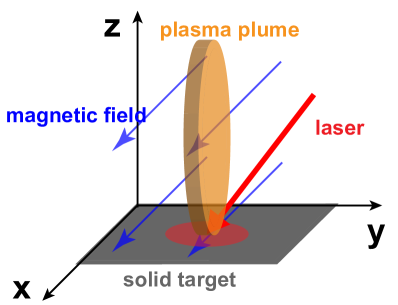
We simulate the typical laser conditions of experiments performed on ELFIE laser [12, 4, 29, 9]. The schematic of the simulation setup is shown in Fig.1, the solid C2F4 target (in grey) is irradiated with a laser pulse (in red) with 17 J energy, 0.5 ns pulse duration (at Full-Width-Half-Maximum), and 1.057 m laser wavelength. The focal spot diameter is 750 m, and the on-target intensity is about W/cm2. The magnetic field (in blue) is uniformly applied along the x-direction with T, and we will focus on the evolution of the plasma plume (in orange).
The simulation box is defined by a uniform Cartesian grid of dimension 8 mm 8 mm 30 mm and the number-of-cells is equal to , the spatial resolution is m, and the simulation duration is ns. Both the box size (along the -direction) and the simulation duration are increased with respect to our former paper [29] in order to investigate the late-time slab propagation. We here consider “outflow” boundary conditions. GORGON solves the resistive MHD equations, uses a vector potential formalism and retain the displacement current in vacuum. This allows the code to model a computational vacuum whose cut-off density is set to kg/m3.
The interaction between the laser and the solid target is performed using the DUED code [32], which solves the single-fluid, three-temperatures equations in two-dimensional axisymmetric, cylindrical geometry in Lagrangian form. The code uses the material properties of a two-temperatures equation of state (EOS) model including solid state effects, and a multi-group flux-limited radiation transport module with tabulated opacities. The laser-plasma interaction is performed in the geometric optics approximation including inverse-Bremsstrahlung absorption. At the end of the laser pulse (about 1 ns), the plasma profiles of density, momentum and temperature from the DUED simulations are remapped onto the 3D Cartesian grid of GORGON. The purpose of this hand-off is to take advantage of the capability of the Lagrangian code to achieve very high resolution in modeling the laser-target interaction. A similar configuration has been used in former works [11, 12, 13, 33, 29].
To remove the axis-symmetry imposed by the DUED simulations when remapping onto the GORGON grid, we introduce a uniformly distributed random perturbation on the plasma velocity components with maximum amplitude % of the initial value. In addition, to reproduce the kink-like perturbations seen in the experiment[29, 9], we impose an asymmetric modulation on the initial plasma velocity between the right and left side of the slab; we also explore Bessel-like modulations, the details of which are given in Sec. III.2.
III 3D SIMULATIONS OF PLASMA EVOLUTION
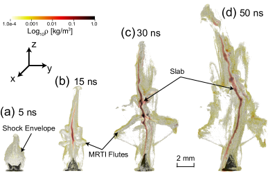
The global dynamics of the plasma plume over 50 ns is shown in Fig. 2. The initial plasma plume expansion is shown in Fig. 2 (a), where we observe the typical diamagnetic cavity and the curved shock envelope that bounds the plasma [29]; the development of the MRTI starts from Fig. 2 (b), where the cavity collapses along the y-direction and a slab is forming from the cavity tip; the development of the flutes and the extension of the slab along the z-direction can be seen in Fig. 2 (c), which already becomes kink-like unstable; and the slab propagation and bending are shown in Fig. 2 (d).
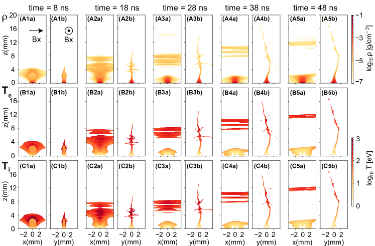
Fig. 3 shows the 2D slices of the mass density , electron temperature , and ion temperature of the plasma plume in both the xz-plane and the yz-plane. Comparing the xz-plane with the yz-plane, it is clear that while the plasma plume has been confined in the yz-plane, it can freely expand in the xz-plane. The detailed plasma parameters are listed in Table 1, together with the deduced dimensionless parameters.
We now focus our attention on the collimation of the plasma plume into a slab and on its propagation.
| Time | 5 ns | 30 ns | 50 ns |
| Region | Shock Envelope | MRTI Flutes | Slab |
| Local Measurements | |||
| Characteristic length [m] | 100 | 100 | 100 |
| Averaged Atomic Number A | 17.3 | 17.3 | 17.3 |
| Effective Charge State | 6.5 | 8.0 | 8.0 |
| Elec. Number Density [cm-3] | |||
| Ion Number Density [cm-3] | |||
| Mass Density [g/cm3] | |||
| Elec. Temperature [eV] | 150.0 | 120.0 | 100.0 |
| Ion Temperature [eV] | 400.0 | 90.0 | 100.0 |
| Flow Velocity [km/s] | 350.0 | 150.0 | 400.0 |
| Magnetic Field Strength B [T] | 25.0 | 29.0 | 30.0 |
| Calculated Dimensionless Parameters | |||
| Elec. Collisionality | 0.06 | 0.6 | 0.2 |
| Ion Collisionality | 0.1 | 0.1 | 0.1 |
| Elec. Magnetization () | 5.0 | 680.0 | 280.0 |
| Ion Magnetization () | 0.03 | 0.5 | 0.3 |
| Mach Number | 3.1 | 1.6 | 4.7 |
| Alfvénic Mach Number | 3.3 | 0.3 | 1.0 |
| Magnetosonic Mach Number | 2.3 | 0.3 | 1.0 |
| Plasma Thermal Beta | 1.4 | ||
| Plasma Dynamic Beta | 22.0 | 0.1 | 2.0 |
III.1 SLAB FORMATION
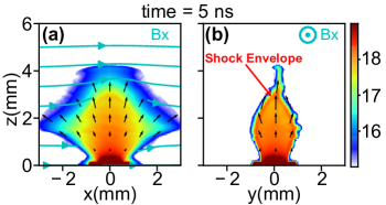
In this section, we review and extend our former work [29] to a higher magnetic field of 30 T, and an increased perturbation amplitude of the initial momentum on the right-half side of the target. As is quantified in Table 1, the initial plasma expansion is dominated by the ram pressure, until almost stagnation around 5 ns, the plasma dynamic , where is the fluid velocity, is the magnetic field strength and is the permeability in vacuum. This would result in an almost free expansion of the plasma in the xz-plane, as is detailed in Fig. 4 (a). The situation is quite different in the yz-plane, as is shown in Fig.4 (b). There, the highly conductive plasma plume expands and pushes the magnetic field away. A pressure balance between the ram pressure of the plasma and the ambient magnetic pressure is achieved and this leads to the end of the diamagnetic cavity expansion [11]. Because the plasma has velocities greater than the fast magneto-acoustic velocity, its deceleration leads to the formation of a curved shock envelope. The magnetosonic Mach number is , corresponding to a supersonic and super-Alfvénic regime (where is the sound speed and is the Alfvén speed). The plasma in the cavity is redirected along the curved shock towards the -direction, where it forms a conical shock at the tip of the cavity, and a jet-like flow in the yz-plane is finally created [11, 12]. Note that the tip of the shock envelope is actually not along the axis. There’s a small bending towards the right, as is shown by the black velocity arrows. This is due to the initial non-axisymmetric momentum perturbation mentioned above.
The characterization of the shock envelope is detailed in the second column of Table 1. The collisionality (the ratio of the mean-free-path to the shock envelope’s length-scale ) of both electrons and ions is smaller than unity, confirming the validity of the fluid description [35]. The Hall parameter (or, the magnetization) of electrons is , indicating that the electrons are strongly magnetized; while ions are not ().
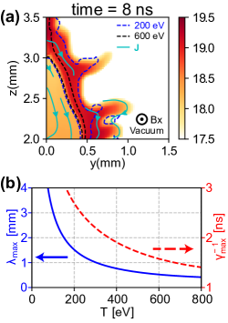
The MRTI requires an effective acceleration or deceleration at an interface between fluids of different mass density, and this basic condition is met at the interface between the plasma and vacuum when the expanding plasma is halted by the magnetic field lines and also when the cavity collapses[36]. As is seen in Fig. 5 (a), a zoom of the structure of the flow along the plasma/vacuum interface shows the growth of the protruding “fingers”, which is one of the characteristic of the MRTI. This inevitably will be triggered if the effective acceleration is anti-parallel to the density gradient (in the frame of the interface). Following the analytical estimate made in our former work [29], in Fig. 5 (b), the MRTI growth time and fastest growing mode are calculated with the parameters of our plasma condition at ns and at the interface, i.e. the mass density kg/m3, the Coulomb logarithm , the atomic number , the effective charge state , and the effective acceleration m/s2, in which m is the width of the shock envelope and km/s is the flow velocity. It is clear that over the temperature range of eV, as the temperature increases, the wavelength of the fastest growing mode flattens to a narrow band of mm, and for these modes the e-folding time is less than 3 ns, which is consistent with the simulations.
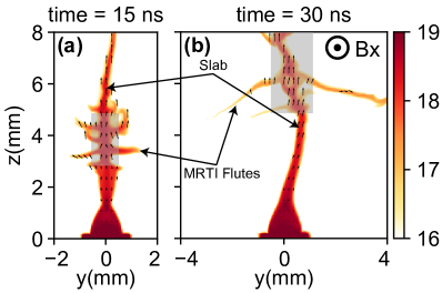
The MRTI initially grows on the outer edges of the cavity but also propagates axially along with the flow. After the initial growth phase, Fig. 6 (a) shows that at ns, the density cavity collapsed around mm, where the MRTI grows rapidly (highlighted by the grey box). At ns, as is shown in Fig. 6 (b), the collapsed region propagates along the -direction, arriving at mm (also highlighted by the grey box). The MRTI flutes end up merging with each other, and elongate along the -direction, reaching mm. In the meantime, their density is dropping, leaving the plasma plume density compressed around while propagating along the -direction, thus forming a dense slab structure whose physical parameters are given in the third column of Table 1.
III.2 SLAB PROPAGATION
We now describe the late-time slab propagation stage, focusing on the kink-like disruption see for example in Fig. 2 (c) and (d), as well as in Fig. 3, which was clearly observed in recent experiments[9].
Comparing Fig. 3 (A3b) and (A4b), it is clear that the propagation of the MRTI-flutes (both in the and directions) leads to a decrease of their mass density, which eventually drops below the vacuum cut off employed in the simulations. Thus at late times, only the central portion of the slab, localized around , is visible. Additionally, we note that in the slab the electron and ion have equilibrated to equal temperatures. Other parameters, e.g. the magnetic field, velocity, etc., are listed in Table 1.
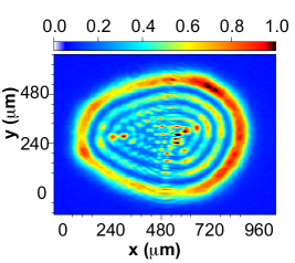
More interestingly, starting from Fig. 3 (3b), it is clear that a kink-like perturbation develops during the slab propagation. Such bending originates from the asymmetric perturbation introduced initially on the plasma momentum. This is inspired by related experiments [29], where the typical spatial pattern of the laser intensity deposition on target is shown in Fig. 7. Beside the relatively less important ring-like radial distributions, the intensity is not axis-symmetric with a clear left to right difference.
We now investigate the effects of an non-homogeneous laser-intensity deposition on the distortions of the slab. The purpose of the simulations is to demonstrate that the kinking of the slab can be simply reproduced by perturbing the initial velocity of the plasma plume, without the added complexity of introducing a non-homogeneous laser intensity profile. Although idealized, these initial conditions demonstrate that they are sufficient to perturb the oblique shock that is then responsible for redirecting the flow axially. In the simulation, the choice of the perturbation on the right being an order-of-magnitude higher than that on the left is to clearly demonstrate this effect within the simulation timescale.
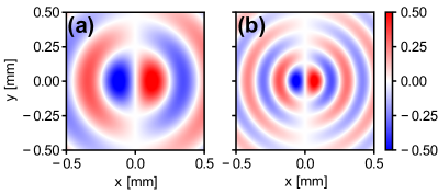
To mimic the ring-like radial intensity distribution, we introduce the following perturbation of the plasma velocity , with a Bessel-like form:
where is the distance to the circle of the laser spot on the target surface ( and are the spatial coordinates), the angle , is the Bessel function of the first kind, and is the n-th root of , is the laser spot radius, as is illustrated in Fig. 8.
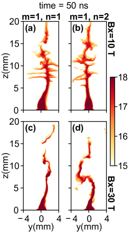
Here, we compare the results of the above two modes (i.e. and ) for different magnetic field strength (i.e. T and T) at ns. Comparing the first row of Fig. 9, with T, the difference between the slab propagation with initial perturbation using Bessel function modes of and is not so obvious. They both show a weak slab bending along the z-direction, and there still exists quite a lot of flutes structures. However, in the second row with T, distinctive differences between those modes can be seen. Besides the bending of the slab, we also see the formation of the kink-like disruption, with patterns much stronger in the mode than that in the mode. The disruption leads to a shorter propagation distance for the mode than that of the mode. The kink-like disruption is clearly more severer with higher magnetic field strength. Note the the simulations shown here are different from the case shown in Fig. 3 (5b), in which the perturbation had no ring-like structure. This further indicates that the particular pattern of the laser spot inhomogeneity plays a crucial role in determining the pattern and the level of the kink-like disruptions. As mentioned above, this is also in accordance with recent experimental observations [9].
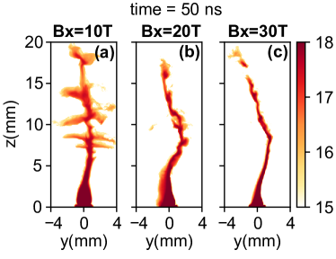
To further investigate the effect of the magnetic field strength on the propagation of the plasma slab, we carried out a series of simulations with a magnetic field increasing from 10 T to 30 T and for fixed laser-plasma interaction conditions (i.e. the same as described in Sec. II). The results are compared in Fig. 10. It is clear that as the magnetic field strength is increased the slab becomes thinner, its density increases, and the amplitude of the kink-like motions became more evident. In addition, as the MRTI is more suppressed with higher magnetic field, the flute structures in the T case are much more obvious than those in the T case, while they completely disappear in the T case. Because as the magnetic field strength increased, the diamagnetic cavity collapses more quickly, leaving shorter time for the MRTI to grow.
IV CONCLUSIONS
In conclusion, the detailed characterization of the overall stability and dynamics of a laser-produced plasma across a magnetic field of tens of Tesla is investigated with large-scale 3D resistive-MHD simulations. It is found that the plasma is first collimated by the magnetic field into a slender slab, whose plasma-vacuum interface is dominated by the MRTI. Later, the flutes fade away, the plasma elongates forming a slab-like structure. We have shown that during its propagation, the slab suffers from kink-like disruptions because of the imbalance of initial perturbation, which originates from the inhomogeneity of the laser-intensity deposition. By mimicking the pattern of a typical laser-intensity profile from related experiment using a Bessel-like function, we find that the kink-like structures observed in the slab are closely linked to the initial velocity perturbations imposed and to the strength of the magnetic field.
ACKNOWLEDGMENTS
This work was supported by funding from the European Research Council (ERC) under the European Unions Horizon 2020 research and innovation program (Grant Agreement No. 787539). The research leading to these results is supported by Extreme Light Infrastructure Nuclear Physics (ELI-NP) Phase II, a project co-financed by the Romanian Government and European Union through the European Regional Development Fund, and by the project ELI-RO-2020-23 funded by IFA (Romania). This work was also granted access to the HPC resources of MesoPSL financed by the Region Ile de France and the project Equip @ Meso (reference ANR-10-EQPX-29-01) of the program Investissements d’Avenir supervised by the National Agency for Research.
References
- Bernhardt et al. [1987] P. Bernhardt, R. Roussel-Dupre, M. Pongratz, G. Haerendel, A. Valenzuela, D. Gurnett, and R. Anderson, Observations and theory of the ampte magnetotail barium releases, Journal of Geophysical Research: Space Physics 92, 5777–5794 (1987).
- Fujioka et al. [2013] S. Fujioka, Z. Zhang, K. Ishihara, K. Shigemori, Y. Hironaka, T. Johzaki, A. Sunahara, N. Yamamoto, H. Nakashima, T. Watanabe, et al., Kilotesla magnetic field due to a capacitor-coil target driven by high power laser, Scientific Reports 3, 1170 (2013).
- Albertazzi et al. [2013] B. Albertazzi, J. Béard, A. Ciardi, T. Vinci, J. Albrecht, J. Billette, T. Burris-Mog, S. Chen, D. Da Silva, S. Dittrich, et al., Production of large volume, strongly magnetized laser-produced plasmas by use of pulsed external magnetic fields, Review of Scientific Instruments 84, 043505 (2013).
- Revet et al. [2017] G. Revet, S. N. Chen, R. Bonito, B. Khiar, E. Filippov, C. Argiroffi, D. P. Higginson, S. Orlando, J. Béard, M. Blecher, et al., Laboratory unraveling of matter accretion in young stars, Science Advances 3, e1700982 (2017).
- Schaeffer et al. [2017] D. B. Schaeffer, W. Fox, D. Haberberger, G. Fiksel, A. Bhattacharjee, D. Barnak, S. Hu, K. Germaschewski, and R. Follett, High-mach number, laser-driven magnetized collisionless shocks, Physics of Plasmas 24, 122702 (2017).
- Kuramitsu et al. [2018] Y. Kuramitsu, T. Moritaka, Y. Sakawa, T. Morita, T. Sano, M. Koenig, C. Gregory, N. Woolsey, K. Tomita, H. Takabe, et al., Magnetic reconnection driven by electron dynamics, Nature Communications 9, 1–6 (2018).
- Slutz and Vesey [2012] S. A. Slutz and R. A. Vesey, High-gain magnetized inertial fusion, Physical Review Letters 108, 025003 (2012).
- Davies et al. [2017] J. Davies, D. Barnak, R. Betti, E. Campbell, P.-Y. Chang, A. Sefkow, K. Peterson, D. Sinars, and M. Weis, Laser-driven magnetized liner inertial fusion, Physics of Plasmas 24, 062701 (2017).
- Filippov et al. [2021] E. D. Filippov, S. S. Makarov, K. F. Burdonov, W. Yao, G. Revet, J. Béard, S. Bolaños, S. N. Chen, A. Guediche, J. Hare, et al., Enhanced x-ray emission arising from laser-plasma confinement by a strong transverse magnetic field, Scientific Reports 11, 1–14 (2021).
- Froula et al. [2007] D. Froula, J. Ross, B. Pollock, P. Davis, A. James, L. Divol, M. Edwards, A. Offenberger, D. Price, R. Town, et al., Quenching of the nonlocal electron heat transport by large external magnetic fields in a laser-produced plasma measured with imaging thomson scattering, Physical Review Letters 98, 135001 (2007).
- Ciardi et al. [2013] A. Ciardi, T. Vinci, J. Fuchs, B. Albertazzi, C. Riconda, H. Pépin, and O. Portugall, Astrophysics of magnetically collimated jets generated from laser-produced plasmas, Physical Review Letters 110, 025002 (2013).
- Albertazzi et al. [2014] B. Albertazzi, A. Ciardi, M. Nakatsutsumi, T. Vinci, J. Béard, R. Bonito, J. Billette, M. Borghesi, Z. Burkley, S. Chen, et al., Laboratory formation of a scaled protostellar jet by coaligned poloidal magnetic field, Science 346, 325–328 (2014).
- Higginson et al. [2017a] D. Higginson, G. Revet, B. Khiar, J. Béard, M. Blecher, M. Borghesi, K. Burdonov, S. Chen, E. Filippov, D. Khaghani, et al., Detailed characterization of laser-produced astrophysically-relevant jets formed via a poloidal magnetic nozzle, High Energy Density Physics 23, 48–59 (2017a).
- Plechaty et al. [2013] C. Plechaty, R. Presura, and A. Esaulov, Focusing of an explosive plasma expansion in a transverse magnetic field, Physical Review Letters 111, 185002 (2013).
- Mostovych et al. [1989] A. Mostovych, B. Ripin, and J. Stamper, Laser produced plasma jets: Collimation and instability in strong transverse magnetic fields, Physical Review Letters 62, 2837 (1989).
- Bruneteau et al. [1970] J. Bruneteau, E. Fabre, H. Lamain, and P. Vasseur, Experimental investigation of the production and containment of a laser-produced plasma, The Physics of Fluids 13, 1795–1801 (1970).
- Matoba and Ariga [1971] T. Matoba and S. Ariga, Motion and collision of plasma blobs produced by giant pulse laser in a transverse magnetic field, Journal of the Physical Society of Japan 30, 1477–1487 (1971).
- Jellison and Parsons [1981] G. Jellison and C. Parsons, Resonant shadowgraph and schlieren studies of magnetized laser-produced plasmas, The Physics of Fluids 24, 1787–1790 (1981).
- Okada et al. [1981] S. Okada, K. Sato, and T. Sekiguchi, Behaviour of laser-produced plasma in a uniform magnetic field–plasma instabilities, Japanese Journal of Applied Physics 20, 157 (1981).
- Ripin et al. [1987] B. Ripin, E. McLean, C. Manka, C. Pawley, J. Stamper, T. Peyser, A. Mostovych, J. Grun, A. Hassam, and J. Huba, Large-larmor-radius interchange instability, Physical Review Letters 59, 2299 (1987).
- Ripin et al. [1993] B. Ripin, J. Huba, E. McLean, C. Manka, T. Peyser, H. Burris, and J. Grun, Sub-alfvénic plasma expansion, Physics of Fluids B: Plasma Physics 5, 3491–3506 (1993).
- Winske [1989] D. Winske, Development of flute modes on expanding plasma clouds, Physics of Fluids B: Plasma Physics 1, 1900–1910 (1989).
- Huba et al. [1990] J. Huba, A. Hassam, and D. Winske, Stability of sub-alfvénic plasma expansions, Physics of Fluids B: Plasma Physics 2, 1676–1697 (1990).
- Peyser et al. [1992] T. Peyser, C. Manka, B. Ripin, and G. Ganguli, Electron–ion hybrid instability in laser-produced plasma expansions across magnetic fields, Physics of Fluids B: Plasma Physics 4, 2448–2458 (1992).
- Hassam and Huba [1990] A. Hassam and J. Huba, Nonlinear evolution of the unmagnetized ion rayleigh–taylor instability, Physics of Fluids B: Plasma Physics 2, 2001–2006 (1990).
- Zakharov et al. [2006] Y. P. Zakharov, V. Antonov, E. L. Boyarintsev, A. Melekhov, V. Posukh, I. Shaikhislamov, and V. Pickalov, Role of the hall flute instability in the interaction of laser and space plasmas with a magnetic field, Plasma Physics Reports 32, 183–204 (2006).
- Tang et al. [2020] H.-b. Tang, G.-y. Hu, Y.-h. Liang, Y.-l. Wang, T. Tao, P. Hu, P. Yuan, P. Zhu, Y. Zuo, B. Zhao, et al., Observation of large larmor radius instability in laser plasma expanding into a 10 t external magnetic field, Physics of Plasmas 27, 022108 (2020).
- Plechaty et al. [2010] C. Plechaty, R. Presura, S. Stein, D. Martinez, S. Neff, V. Ivanov, and Y. Stepanenko, Penetration of a laser-produced plasma across an applied magnetic field, High Energy Density Physics 6, 258–261 (2010).
- Khiar et al. [2019] B. Khiar, G. Revet, A. Ciardi, K. Burdonov, E. Filippov, J. Béard, M. Cerchez, S. Chen, T. Gangolf, S. Makarov, et al., Laser-produced magnetic-rayleigh-taylor unstable plasma slabs in a 20 t magnetic field, Physical Review Letters 123, 205001 (2019).
- Chittenden et al. [2004] J. Chittenden, S. Lebedev, C. Jennings, S. Bland, and A. Ciardi, X-ray generation mechanisms in three-dimensional simulations of wire array z-pinches, Plasma Physics and Controlled Fusion 46, B457 (2004).
- Ciardi et al. [2007] A. Ciardi, S. Lebedev, A. Frank, E. Blackman, J. Chittenden, C. Jennings, D. Ampleford, S. Bland, S. Bott, J. Rapley, et al., The evolution of magnetic tower jets in the laboratory, Physics of Plasmas 14, 056501 (2007).
- Atzeni et al. [2005] S. Atzeni, A. Schiavi, F. Califano, F. Cattani, F. Cornolti, D. Del Sarto, T. Liseykina, A. Macchi, and F. Pegoraro, Fluid and kinetic simulation of inertial confinement fusion plasmas, Computer physics communications 169, 153–159 (2005).
- Higginson et al. [2017b] D. Higginson, B. Khiar, G. Revet, J. Béard, M. Blecher, M. Borghesi, K. Burdonov, S. Chen, E. Filippov, D. Khaghani, et al., Enhancement of quasistationary shocks and heating via temporal staging in a magnetized laser-plasma jet, Physical Review Letters 119, 255002 (2017b).
- Trubnikov [1965] B. Trubnikov, Particle interactions in a fully ionized plasma, Rev. Plasma Phys. 1 (1965).
- Ryutov et al. [1999] D. Ryutov, R. Drake, J. Kane, E. Liang, B. Remington, and W. Wood-Vasey, Similarity criteria for the laboratory simulation of supernova hydrodynamics, The Astrophysical Journal 518, 821 (1999).
- Khiar [2017] B. Khiar, Laboratory astrophysics with magnetized laser-produced plasmas, Theses, Université Pierre et Marie Curie - Paris VI (2017).