Current Affiliation: ]Unité Mixte de Physique CNRS, Thales, Université Paris-Saclay, Palaiseau 91767, France
Exceptional sign changes of the non-local spin Seebeck effect in antiferromagnetic hematite
Abstract
Low power spintronic devices based on the propagation of pure magnonic spin currents in antiferromagnetic insulator materials offer several distinct advantages over ferromagnetic components including higher frequency magnons and a stability against disturbing external magnetic fields. In this work, we make use of the insulating antiferromagnetic phase of iron oxide, the mineral hematite -Fe2O3 to investigate the long distance transport of thermally generated magnonic spin currents. We report on the excitation of magnons generated by the spin Seebeck effect, transported both parallel and perpendicular to the antiferromagnetic easy-axis under an applied magnetic field. Making use of an atomistic hematite toy model, we calculate the transport characteristics from the deviation of the antiferromagnetic ordering from equilibrium under an applied field. We resolve the role of the magnetic order parameters in the transport, and experimentally we find significant thermal spin transport without the need for a net magnetization.
I Introduction
The quanta of magnetic excitations, known as magnons, efficiently transport angular momentum in magnetic materials including ferromagnetic [1, 2] and antiferromagnetic insulators (AFMI) [3, 4, 5].
Such magnon spin currents can be excited in AFMIs by several external stimuli including an interfacial spin-bias [3, 4, 5, 6], magnetic resonance [7, 8, 9] or a temperature gradient [8, 10, 11, 12].
This third effect is known as the spin-Seebeck effect (SSE) where the combination of a magnetic field and thermal gradient induces a magnonic spin current [8, 10, 11, 12, 13, 14].
If a heavy metal (HM) with a large spin orbit coupling is placed in contact with the AFMI, this magnon current can be converted to a charge current and thus detected due to the inverse spin Hall effect (ISHE) [8, 10, 3, 15].
However, whether the spin current can be detected has been shown to depend on the symmetry of the antiferromagnetic ordering with respect to both and [12, 10, 13].
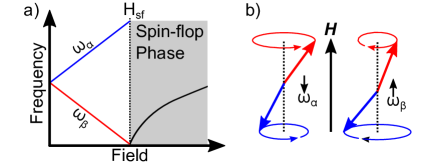
The generation of a magnonic spin current by a thermal gradient offers an attractive alternative for magnonic applications and even the local, active manipulation of magnon currents excited by other mechanisms [16]. Furthermore, using antiferromagnetic materials as magnonic spin current conduits offer several benefits over ferromagnetic materials including a resilience to external disturbing magnetic fields and higher frequency magnon excitations [17]. Bilayers of AFMI/Pt have previously been employed to investigate the locally generated voltage in response to an interfacial temperature gradient applied out of the sample plane, perpendicular to the antiferromagnetic anisotropy direction and the detected transversal voltage [13, 10, 18, 14, 8]. The used AFMIs have a uniaxial anisotropy, such that a spin-flop, where the antiferromagnetic Néel vector spontaneously rotates , is induced for a magnetic field applied parallel to the anisotropy easy-axis. While in some systems, a signal below the spin-flop field was observed and in others not, the consensus is that the spin-flop has a strong impact on the local SSE signal. These measurements are explained by making use of a magnon spin diffusion model based on degenerate magnon modes. This degeneracy is broken in the presence of a magnetic field, leading to a net imbalance between the two lowest, modes and thus a detectable magnon current [12]. So far for the thermally driven spin current, no high field suppression associated to magnon suppression (as seen in the ferrimagnetic insulator Y3Fe5O12(YIG) [19]) has been observed even above the spin-flop field where an increasing field serves to increase the magnon gap. It has been suggested that the thermally induced voltage is directly related to the net magnetization [13, 14] but this is disputed for instance for the AFMI -Cu2V2O7 [18], suggesting that the AFM-SSE depends not only on the magnetic properties but also the transport properties of the investigated AFM, where the magnon relaxation time dominates the transport, particularly at low temperatures. Crucially, these previous studies have all found a strong suppression of the local SSE with increasing temperature. At low temperatures, a peak in the local SSE voltage has been reported, explained via the competing contributions of the two lowest magnon modes [12]. The increasing temperature leads to an increase in the population of the lowest, magnon mode [see Fig. 1], until the thermal energy overcomes the magnon gap of the higher energy mode. These two magnon modes contribute to the net observed voltage with opposing signs, and thus a maximum occurs just below the temperature required to overcome the magnon gap of the higher energy mode [12].
The application of the magnetic field perpendicular to , such that the magnetic sublattices cant in the direction , leads to a net magnetization.
This configuration has also been shown to elicit a response [13, 14] but the importance of the net magnetization for the transport is disputed [10, 18].
Moving away from local thermal gradients across the interface, the non-local SSE (NL-SSE) has also very recently been investigated in AFMIs where now exists between two non-magnetic metal electrodes [3, 20, 21, 22, 12, 23, 24, 25].
It was found that a large field induced magnetization parallel to the transport direction was required to enable significant spin transport of thermally excited magnons [3, 20, 21, 22].
An increase in temperature led to a sharp suppression of the NL-SSE, just as for the local signal [22, 20, 21, 23], however, a significant signal was still reported at for -Fe2O3 [3].
Very recently, it was also suggested that the NL-SSE in antiferromagnets may be super-imposed by the transverse spin Nernst effect [26], however for the work performed here, the transverse spin Nernst effect can be excluded as a major effect due to geometrical considerations.
The transported spin current due to a thermal gradient is given by , where is the magnon conductance, is the net magnon population between the different contributing modes and is the spin Seebeck conductance.
Antiferromagnets exhibit two magnetic order parameters, the staggered Néel vector and a net magnetization that can appear under an applied field.
This then means that has contributions related to each order parameter; the Néel order spin Seebeck conductance and the magnetic moment spin Seebeck conductance [12, 11].
Each of these comes with additional transport and dissipation paths for thermally excited magnons and has a distinct field and temperature dependence [12, 11].
Generally, based on the observations in both local and non-local spin Seebeck measurements, so the key the question is of whether can enable significant spin transport over long-distances at elevated temperatures.
In this work we demonstrate that the application of a magnetic field parallel to the easy-axis of a bulk crystal of the insulating antiferromagnetic iron oxide hematite (-Fe2O3) elicits a non-local spin Seebeck effect mediated by the Néel vector. Magnons are efficiently transported both parallel and perpendicular to the applied field with distinct dependencies and we show that the applied field breaks the degeneracy of the available magnon modes facilitating a net transport along the thermal gradient direction. Finally, we develop a toy model of thermal transport in hematite, where we are able to resolve some of the key experimental observations. We utilize -Fe2O3 because it has been shown to facilitate long-distance magnon transport excited by in interfacial spin-bias [3, 6, 4, 5], a low magnetic damping [6, 27] and a controllable magnetic order in bulk crystals and thin films [28, 29, 30]. Below the Morin temperature [31], this material adopts an easy-axis (EA) anisotropy where the Néel vector aligns parallel to the crystallographic c-axis [28, 29]. An antisymmetric exchange interaction, the Dzyaloshinskii-Moriya interaction (DMI), parallel to the c-axis is present in this material and leads to a reorientation of under an applied field if a finite angle between and the EA exists [28, 29].
II Thermal Magnon Transport Along the Easy Axis
We start by investigating the efficiency of magnon transport in -Fe2O3 parallel to the easy-axis. Electrically excited magnons have been shown to be efficiently transported by the Néel vector [3, 4], but so far, the Néel spin Seebeck coefficient has been shown to be too small to elicit significant signals [22, 3, 21, 20].
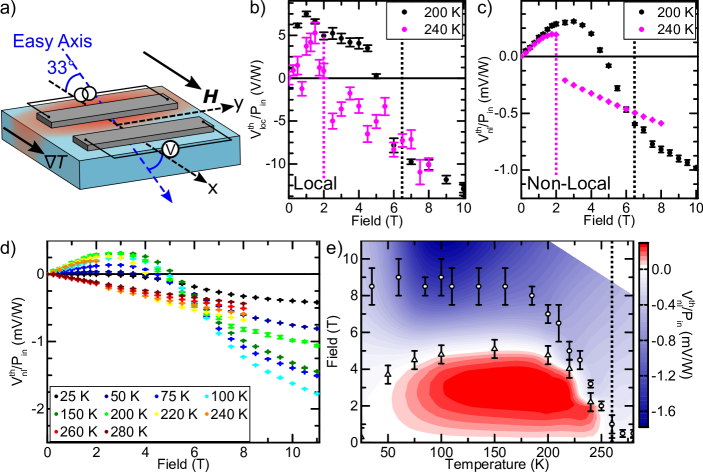
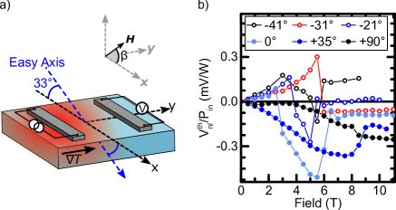
Using lithographic methods [3, 4], we define a non-local geometry of Pt wires, wide and long, separated by atop a commercially obtained -Fe2O3 bulk crystal, orientated as (102) such that the easy-axis is inclined to the surface plane [see Fig. 2a)].
A charge current is applied to one wire, which leads to Joule heating of the underlying magnetic material, generating a thermal gradient between the two wires, and the excitation and flow of thermally excited magnons due to the SSE [1, 32, 12, 24].
The second Pt wire acts as a detector, absorbing the flowing spin current underneath, converted to a measurable voltage by the ISHE.
The non-local SSE (NL-SSE) voltage is defined as where () is the non-local voltage detected for a positive (negative) current , where we invert the current to remove any offsets and isolate the thermal signal.
is then normalized to the input power where the resistance of the injector takes into account any change in the resistance due to the spin Hall magnetoresistance (SMR) [28, 33, 34, 35, 36, 37].
During the fabrication process, the Pt/-Fe2O3 interface is subject to a baking step exceeding , higher than any Joule heating we may reach during our experiments, allowing us to exclude any impact on Joule-heating-driven annealing of the interface [38, 39].
We fix the orientation of an external field parallel to the in-plane projection of the easy-axis, such that is at an angle of to the easy-axis [see Fig. 2a)].
Below in the easy-axis phase, this will induce a spin-reorientation at some critical magnetic field where will reorientate perpendicular to [29, 28].
Above , a field induced magnetization will appear directed along and a net moment will appear out of the sample plane [see also Appendix A].
We first adopt the geometry shown in Fig. 2a) where the thermal gradient , transport direction and magnetic field are coincident.
As well as the thermal gradient between the wires, there will also be a secondary thermal gradient across the Pt/-Fe2O3 interface that can lead to a local SSE [10, 13, 18].
The thermally excited voltage due to the local SSE is shown in Fig. 2b) as a function of the applied magnetic field for several temperatures below .
Given the nature of the excitation, we cannot ascertain the precise thermal gradient across the interface, but we can resolve the measured voltage as a function of the input power.
If the deposited power is increased, the local signal remains the same (see Appendix B), although it can change the nature of the non-local signal discussed later.
Close to , the signal is noisy, likely due to the thermal fluctuations that accompany the transition around this temperature but the net trend is a small signal below that changes sign and increases in amplitude linearly above .
Despite the thermal fluctuations, this observation of a finite local SSE also occurs at the highest temperature so far reported for an antiferromagnet [10, 13, 18, 14, 8, 22].
Further below , the signal below more defined due to the reduced thermal fluctuations and also changes sign in the vicinity of and the amplitude is linear by increasing with increasing magnetization.
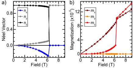
If we consider the individual components of and for these local measurements [see Appendix Sec. A, Fig. 5], the signal above is dominated by the emerging magnetization as previously reported. Below , the field-evolution of does not follow that of our experimental results indicating that the orientation of is not sufficient to drive the signal we observe and instead represents a combination of a local SSE mediated by both the Néel vector and the magnetization.
The presence of a finite, local signal below has been reported [10, 18, 14, 11] and explained by differences in population of the contributing magnon modes under an applied field, but only at low temperatures below the thermal energy of the higher energy mode [Fig. 1a)].
In this work however, the temperature of the surrounding environment will lead to thermal population of many magnon modes, not just the lowest mode.
Moving to the non-local transport of thermally excited magnons, the lateral thermal gradient and are coincident and we would naively expect little, to no transport in the absence of a significant net magnetization below [see Appendix A].
However, surprisingly, we find an observable and increasing non-local signal below the spin-reorientation field in the easy-axis phase just below at [Fig. 2c)].
The signal reaches a maximum at = .
Just above this field, there is an abrupt inversion of the signal coincident with the spin-flop field at this temperature [28, 29].
Above , the NL-SSE is linear with increasing field, consistent with an emerging field induced magnetization parallel to the transport direction [3, 10, 12].
We note that the finite angle between the magnetic field and the easy-axis leads to a finite magnetic moment along the transport direction [see Fig. 5], even below the critical field. One could then attribute the non-local signal observed entirely to this net moment. However, the moment along increases almost linearly with the applied field, showing little change at , at odds with our experimental observations. Comparing this to the magnitude of the moment along or the orientation of the Néel vector, where significant changes happen, the net trend of the field-induced magnetization is insufficient to explain our experimental results.
The presence of a significant signal below the spin-reorientation indicates that the Néel order spin Seebeck conductance contributes significantly to the signal [12, 8, 11].
In the absence of a magnetic field, the two lowest magnon modes contributing to the net transport are degenerate and no net transport is observed.
The application of a magnetic field breaks this degeneracy (as explained schematically in Fig. 1a)), and net transport is conceivable even without a net magnetic moment providing that is reasonably large [12].
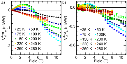
By cooling further below , the magnetic field required to induce a spin-reorientation moves to higher magnetic fields, becoming constant at low temperatures [28, 29]. The NL-SSE at is shown in black in Fig. 2c). Similar to at , a significant, increasing signal appears with the application of a magnetic field due to the broken degeneracy of the magnon modes. However, contrary to the case of , rather than increasing up to the spin-flop field, a turning point appears at , above which the signal turns negative at and experiences a change in gradient at the spin-flop field . Whilst closer to , the behavior was consistent with a more localized SSE as presented by Ref. [11], the response at this lower temperature cannot be so easily interpreted. It was recently discussed by Wimmer et al. [40] that the long distance transport of magnons can be achieved through a superposition of arbitrarily polarized magnon modes in an effect akin to a magnon Hanle effect [41]. The application of a magnetic field leads to modulation of the magnon frequencies, even leading to a “beating” of the magnon transport [40, 42, 41]. While it is possible that such an effect could be employed to understand the sign change of the NL-SSE, these previous works have focused on antiferromagnets with a hard-axis anisotropy, where the magnon modes are linearly polarized and excited by a spin-polarized interfacial accumulation. In the case of thermally excited magnons, where there is no selective excitation of the magnon modes, there is no expected modulation of the net response with applied field for easy-axis or hard-axis antiferromagnets [12]. Finally, a beating of the magnon transport should also be visible when the distance between the two Pt wires is varied. As we show in the Appendix C, we observe the same behavior of the magnon transport, which would only occur if the distances were exact multiples of the beating wavelength, which is unlikely. We observe that we can resolve a sharp transition at the spin-flop, when the angle between field and easy-axis is reduced further (see Appendix D). This demonstrates that, with the complete absence of a net magnetization along the transport direction, that the Néel spin Seebeck conductance is capable of transporting a magnon current. Once a finite angle is introduced between the field and easy-axis, this transition softens, and we resolve a turning point indicating that the magnetic and Néel spin Seebeck conductances are competing with similar magnitudes but opposing signs despite the differences in the relative perturbation sizes (see Appendix A). Whilst the local SSE [Fig. 2b)] represents a net response of all available magnon modes with a finite polarization perpendicular to the Pt wire, the non-local SSE [Fig. 2c)] only has contributions from magnon modes that propagate across 500 nm (see also Appendix C) and can be detected. The magnon propagation length in AFMs has been shown to be dependent on the frequency, indicating that the filtering out of higher frequency magnon modes with decreasing temperature will correspondingly affect the magnon propagation length at a given temperature [43]. Meanwhile, the application of a field, even below the spin-flop, will significantly alter the frequencies of the contributing modes [Fig. 1a)]. Quantitatively, the application of the field at initially breaks the degeneracy, enabling spin transport which increases as the degeneracy is broken further. As the frequencies of the magnon modes are changed by the magnetic field, the relative populations will also change. As discussed previously, different magnon modes contribute to the net spin Seebeck with differing signs [12, 14], and the propagation lengths will continuously change with changing frequency [43]. Eventually the mode character changes at the spin-reorientation and the signal adopts a linear increase with field due to the emerging . Hoogeboom et al. [22] very recently discussed the transport of thermally excited magnons in the easy-plane antiferromagnet NiO, where the magnetic structure is very similar to the configuration we have above or above . They found reasonable agreement between the non-local transport and the field dependence of the lowest k=0 magnon mode at low temperatures. However, Hoogeboom et al. apply a magnetic field within the antiferromagnetic easy-plane as compared to our field, which is maintain along at all times. This then leads to the magnon dispersions of -Fe2O3 above and NiO being very different. Given this complexity, determining the exact contributions of different modes is out of the scope of this work, which instead focuses on the contributions of the magnetic order parameters to the net transport. Qualitatively, we can interpret the experimental results in terms of the population of different magnon modes [Fig. 1] which contribute to the signal [12]. With reducing temperature, the available magnon modes should correspondingly be reduced. If the non-local signal observed here is dominated by lower energy magnon modes, a reduction in temperature should not lead to significant changes to the signal other than the critical spin-flop field increasing until we decrease below the thermal energy required to populate the second lowest mode, where the signal should exhibit a peak [10, 12]. We show in Fig. 2d) and 2e) the non-local signal, normalized to the heating power based on the heater resistance for several temperatures. With decreasing temperature below we observe that the overall shape of a positive increase followed by a sign inversion is a common trend, however, the transition between the two regimes becomes increasingly smooth at lower temperatures. Above , where -Fe2O3 adopts a canted easy-plane anisotropy, the application of (along the same direction as below ) leads to a linearly increasing moment parallel to the field, represented by the linearly increasing NL-SSE signal observed (confirming our previous measurements of a linearly increasing NL-SSE above where the antiferromagnetic configurations are similar). The similar shapes below would indicate that similar magnons are contributing at each temperature, and these magnons can propagate over large distances with no evidence of a distance-dependent sign change [25] (see also Appendix C). The magnitude of the NL-SSE is shown in Fig. 2e) with the spin-reorientation field [28] and the field where the signal inverts indicated. As exemplified in Fig. 2c), the spin-reorientation and inversion fields are not the same and diverge with decreasing temperature below .
III Thermal Magnon Perpendicular to the Easy Axis
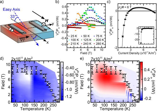
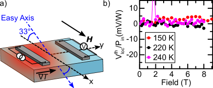
Next, we show in Fig. 3a) a non-local geometry now rotated by , such that and the transport direction are perpendicular to both and the in-plane easy-axis component, which is parallel to .
For this geometry, the perpendicular alignment of the magnetic field and the transport direction means that a magnetization will not appear directed along for any magnitude of applied field, allowing us to completely exclude any significant contributions.
The absence of is confirmed through measurements of the local SSE (see Appendix E), where there is no discernable signal increasing with magnetic field, consistent with previous reports for the AFM-SSE and expected from the parallel alignment of and the voltage detection [10, 13].
We can also confirm this numerically by calculating in Appendix A the different components of the magnetization and Néel vector under an applied magnetic field.
The geometry can also be investigated in the non-local configuration where we expect no significant transport to occur perpendicular to the magnetic anisotropy axis as previously discussed [22, 23, 3, 12, 24].
However, as seen in Fig. 3b), we see for all temperatures a significant signal above and below with a drastically different evolution to the previous geometry.
At temperatures closer to the Morin transition – such as for example – the NL-SSE is initially constant around zero at low magnetic fields. We observe that, as we approach , the NL-SSE shows a sharp negative dip before reaching a smooth maximum at around (close to the measured value of at the temperature for a angle between and the easy-axis [28]). Following this peak, the signal smoothly and gradually decreases with increasing magnetic field. We suggest that the sharp oscillations of the signal at fields below come from fluctuations of the Néel vector as the magnetic anisotropy is compensated by the applied magnetic field. Following the spin-flop, where the Néel vector is now aligned parallel to the transport direction (see Appendix A), the increasing magnetic field will lead to a canting of the magnetic sublattices in the direction of . This canting will serve to reduce the projection of on the transport direction, similarly reducing the observed signal. We can also exclude to projection of a magnetization along for any applied field along (See Fig. 5 in the Appendix). However, as we move to temperatures away from , we no longer observe the fluctuation of the signal before the peak.
Instead, continues to increase from and peaks at some magnetic field value, where the peak values moves to larger magnetic fields with decreasing temperature, indicating that this peak is related to the magnetic structure of the antiferromagnet and thus, intrinsically the antiferromagnetic anisotropy [28, 29].
We note that, whilst the peak closer to coincides with the value of , the peak at lower temperatures occurs at lower magnetic fields than measured for (e.g. at while is closer to ) [28]. This is an effect of the finite angle between and the easy-axis leading to a continuous rotation of across a larger field range [28]. If we reduce the angle between and the easy-axis, we resolve a sharp transition at (Appendix D).
The decrease at high magnetic fields, may also be related to the magnon gap appearing above the spin-flop, similar to the high-field suppression of the SSE seen in ferrimagnetic YIG [19].
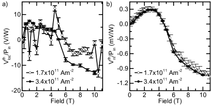
However, this behavior depends on the magnitude of the input power, where we see that our signal changes sign with increasing power, which we show in Fig. 3c) at and an applied field equal to the spin-reorientation field () [28, 3].
A similar effect has been reported for ferrimagnetic YIG, characterizing a transition between a more localized and non-local SSE [1], however this is very different to what we observed for the orientation of Fig. 2 (see Appendix B).
Furthermore, we see that at very large heating power, we again find a negative signal.
Without normalizing to , we observe a predominantly quadratic dependence of the voltage, confirming that the observed signal is indeed thermal in origin.
This behavior is present across all temperatures investigated.
It was stated by Shan et al. [38] that the non-local SSE depends on the boundary conditions of the magnon current, meanwhile recent work has also highlighted the impact of the antiferromagnetic domain structure on magnon transport [22, 4]. The presence of such domain walls could then alter the boundary conditions of the propagating magnon currents. However, we can exclude the possibility of antiferromagnetic domain walls between our Pt wires given that we utilize a bulk -Fe2O3 crystal with domains of hundreds of [3]. Furthermore, the strong temperature dependence of the anisotropy of -Fe2O3 [28, 29] could also lead to temperature induced changes of the antiferromagnetic state. This could possibly lead to these sign changes as a function of the input power through altering the magnon chemical potential and locally changing the anisotropy, especially close to [32].
We summarize the field and temperature dependence in Fig. 3d) and 3e) alongside the spin-reorientation field for two input current densities.
Given that the magnetic field direction and wire separation are maintained, the available and excited magnon modes (Fig. 1) should be identical to the geometry of Fig. 2a). This then raises the question of what leads to the net spin transport perpendicular to the applied magnetic field. We find that we cannot reproduce these experimental findings using our theoretical model (see next section) so it is clear that the origin of thermally excited magnon transport perpendicular to the easy-axis requires further study. It may be that the differences lie in magnon modes further in the Brillouin zone than just the modes. Experimentally, we are detecting a voltage that encompasses all the available magnon modes propagating perpendicular to the easy-axis with a finite component of the polarization perpendicular to the Pt detector. It has been shown for ferrimagnetic YIG that the local SSE has a significant contribution not only from the mode, but also from magnons throughout the Brillouin zone [12, 44]. Furthermore, there are asymmetries in the spin-wave dispersion in -Fe2O3 between spin-waves parallel and perpendicular to the easy-axis [45]. Measurements of the spin-wave dispersion in -Fe2O3 both parallel and perpendicular to the easy-axis direction find velocities of 24 and 31 km/s, respectively, as well as a gap at the edge of the Brillouin zone between the acoustic and optical branches [45, 46]. The spin-waves are at far higher energies than those of the otherwise similar antiferromagnet Cr2O3 [45, 46], which has been the subject of both local [13, 23] and non-local [20, 23] SSE measurements. Evidence of spin transport perpendicular to the easy-axis in this case may also be related to the exchange interaction of -Fe2O3 as compared to for instance Cr2O3. The strongest exchange paths of -Fe2O3 are the weakest in Cr2O3 (in other words, the relative strength of the exchange interaction for the nearest neighbors that significantly contribute giving rise to different exchange constants where is the order of neighbor) due to differences in the cation-cation distance of these two antiferromagnets[45, 46]. The exchange paths are also different to the previously studied fluorides MnF2 [45, 10] and FeF2 [45, 14] so may contribute to the observed differences. Finally, there is the possible contributions arising from the additional DMI present in the system, an interaction absent in all previously investigated antiferromagnets.
IV Atomistic spin model
Having established that significant magnon transport is possible in antiferromagnetic -Fe2O3 mediated by the Néel vector both parallel and perpendicular to the easy-axis, we develop in this section a toy model for the transport in this material. For this, we utilize the following classical, atomistic spin model [47]: it comprises Heisenberg spins, i.e. normalized magnetic moments , which can point in every three-dimensional spatial direction. These spins are positioned on regular lattice sites , where we assume a simple cubic (sc) lattice with lattice constant . The spin Hamiltonian reads
| (1) |
taking into account the exchange interaction, quantified by the exchange Matrix , where the sum over runs over the neighbors of , labelled by ,—counting each pair interaction twice in the double sum.
These matrices split into the isotropic Heisenberg contribution (scalar part), the two-ion anisotropy (traceless, symmetric part) and the Dzyaloshinskii-Moriya interaction (antisymmetric part).
Furthermore, a uniaxial anisotropy with respect to the direction with anisotropy constants and is included, parametrizing second- and fourth order contribution.
A homogeneous magnetic field enters the Zeeman term.
The Landau-Lifshitz-Gilbert (LLG) equation of motion [48, 49, 50] governs the time evolution:
| (2) |
describing the motion of a spin in its effective field , where is the gyromagnetic ratio and the Gilbert damping constant. Finite temperatures enter the model via a Gaussian white noise [51], satisfying
Numerically the LLG equation is solved by the stochastic Heun method [47].
The four atoms—denoted A, B, C, D—of the -Fe2O3 unit cell are placed in the form of layers onto the sc lattice, i.e. if are the lattice indices, atoms of sublattice A are positioned on sites with , those of sublattice B on sites with and so on.
The result is an antiferromagnet layered along the direction.
Note that as in the actual hematite unit cell, sublattices A and D align parallel, and these are antiparallel to B and C [52].
Our system is of a size , when orientated to study the transport along the easy-axis [Fig. 4a)].
The finite cross section in - and direction ensures thermal stability of the magnetic order at the temperatures we investigate in this study.
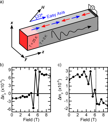
We parameterize this model as discussed in the Appendix A, where we also calculate the components of both and under an applied magnetic field. The thermal excitation is modelled by a temperature step similar to previous works [53, 54]
| (5) |
We also tested a linear temperature gradient, which delivers qualitatively and quantitatively the same results, such that we use a temperature step in the following because of its simplicity.
The thermal fluctuations in the hot area excite magnons, which propagate into the cool area—along the direction—and are damped away due to Gilbert damping.
The geometry is sketched in Fig. 4a).
Each sublattice carries a normalized magnetization , , from which the system’s Néel vector and the magnetization follow. The thermal excitation in steady state leads—on average—to a change of both properties as a function of position . We study this change as a function of magnetic field: and denote the equilibrium values for a given magnetic field, and we define the deviation of the Néel order- and spin accumulation, by
The static magnetic field is tilted by with respect to the easy-axis: [as shown in Fig. 4a))]. This same angle between the easy-axis transport direction and the field allows us to compare the calculations with the experiment: in the model the transport is along the easy-axis and the magnetic field is tilted, whereas in the experiment this is reversed. This difference is due to the requirements of the numerical treatment. However, since the detected signal in the experiment is most likely dominated by the components along the transport direction, i.e. the components along the field, we can thus assume that the projection of the accumulations onto the direction of the magnetic field direction is the property to evaluate for a comparison of model and experimental results:
Fig. 4 depicts the resulting Néel order- [Fig. 4b)] and spin-accumulation [Fig. 4c)] at position as a function of magnetic field.
Around the spin-flop ( in the model), we see a large scattering of both and , however, this is due to numerical uncertainties, which stem from the fact that here it is very hard to calculate the respective equilibrium positions of Néel vector and magnetization.
At the same time this also makes it hard to ascertain proper error bars in this region.
Looking at the general trends away from the spin-flop field, both show a non-monotonic behavior and a sign change, which is, however, always in the vicinity of the spin-flop field.
Furthermore, both start at a non-zero value for zero field, which is expected for the Néel accumulation, but not the spin accumulation.
This offset originates from numerical inaccuracies in the parameters being used – specifically in the exchange matrices.
These have small but finite imbalances among the different sublattices, which cause a very small spurious magnetization at finite temperature as the sublattices do not demagnetize uniformly with increasing temperature.
These numerical errors only occur at finite temperatures and are therefore not evident in the equilibrium magnetization curve (Fig. 5 in the Appendix).
But they are visible when compared to the small non-equilibrium spin accumulation due to the temperature gradient.
More accurate exchange matrices would eliminate this offset, which is however not significant for our findings.
Above the spin-flop, the spin accumulation seems to increase with field, whereas the Néel accumulation tends to decrease, however, in either case the field dependence is rather weak here.
It is worth noting the is several orders of magnitude larger than .
This is due to the large exchange energy present in antiferromagnets and the relation between the Néel vector and the magnetization.
A perturbation of the Néel vector is related to the magnetic anisotropy along the easy-axis alongside the exchange energy, while perturbations of the magnetization are competing with the strong exchange energy.
Therefore it is easier to alter the Néel vector by an external bias (as a temperature gradient for instance) compared to the magnetization.
We next qualitatively compare the experimental results we obtain, with several key features of an increase and maximum of the signal below the spin-flop, an inversion and a linear increase above with the theoretical calculations of the Néel order- and spin- accumulations in Sec. IV [Fig. 4b) – c)].
We find agreement between the atomistic results and experiments for some features, but also differences:
The non-monotonic progression of the experimental data allows for a maximum of the detected signal at a finite field away from the spin-flop field. Meanwhile in our toy model, if we assume that below the spin-flop the spin accumulation dominates the signal, the spin-accumulation increases slightly up to the vicinity of the spin-flop field.
Furthermore, as in the experiments, there is a sign change in both and , but not significantly below the spin-flop field.
A monotonic increase of the signal observed in the experiment at high fields is also consistent at least with the spin accumulation [Fig. 4c)], but not in line with the Néel accumulation [Fig. 4b)], highlighting the importance of the net magnetization above the spin-flop.
Measurements of the thermal magnon transport performed for varying angles between and the easy-axis show a varying behavior which may hint at the origin of the transport but is outside the scope of the current work [see Appendix D].
While key features are reproduced, there are many reasons for the differences between experiments and the model: In the theory we have a clean magnetic order, i.e. domain formation can be ruled out [4, 25], however, considering that we make use of a bulk crystal here, any domains are far larger than the transport scales we are considering [3]. Also we do not account for any disturbances that might be present at the hematite/Pt interface, i.e. roughness or proximity effects. The calculation is furthermore carried out at a base temperature of zero Kelvin, which arguably also makes a difference. Last but not least there is a large uncertainty, how each of the accumulations contributes to the experimentally detected signal. The importance of each contribution may also vary with field as the Néel vector reorients by at the spin-flop. Hence, the complex field and temperature dependence and also differences between experiment and model underline the complex behavior of the spin transport in this system, which requires a deeper understanding of the microscopic details.
V Conclusion
In conclusion, we have observed the transport of thermally excited magnon spin currents in the absence of a significant field induced magnetization parallel to the transport direction. The contribution to the net signal of different magnon modes leads to a complex field dependence below the spin-flop field. Above the spin-flop field, a signal with an amplitude proportional to the field induced magnetization appears. We also observe transport perpendicular to the applied magnetic field, where no magnetization appears, contrary to previous reports on uniaxial antiferromagnets. Our results highlight the importance of the Néel order spin Seebeck conductance for the complex behavior of magnon transport in antiferromagnetic materials under an applied magnetic field offering additional routes for tuning the transport of magnonic spin currents in antiferromagnetic insulators.
Appendix A Parameter Choice for Atomistic Spin Model
Finding suitable parameters for the atomistic calculations is challenging: here we use a combination of ab-initio based parameters and fits to experimentally known properties.
First, and with the absolute value of the free-electron gyromagnetic ratio and the Bohr magneton follow from experiments.
Second, the exchange matrices for the real hematite structure are calculated by density functional theory (DFT) in terms of the screened Korringa–Kohn–Rostoker method [55, 56, 57].
These interactions turn out to be rather long ranged and since an accurate description of hematite is beyond the scope of work, we instead have to map these to our toy-model hematite.
This is carried out by first mapping the DFT values to mean-field parameters (one matrix for each interaction of one sublattice with another), then this is partitioned on the existing interactions in the toy model.
This partitioning is done such that it roughly represents the relative importance of the interactions strength with distance of the original DFT results, e.g. the isotropic part is strongest for next-nearest neighbours.
The on-site anisotropy constants are chosen according to , a ratio known from mean-field modelling in the literature [52], and such that the spin-flop fields are close to the experimental values [29, 28].
For the Gilbert damping we assume , which is likely higher than the actual value of a high-quality single crystal [6], however, we choose a value that does not require excessively large systems for the numerical studies.
Having chosen an appropriate parameter set, we can calculate the equilibrium position of the Néel vector and magnetization under an applied field, devolving both into their respective , and components, Fig. 5.
Appendix B Current Dependence for Transport Parallel to the Easy Axis
In Fig. 3, a significant difference was observed between two current densities passed through the Pt injector wire, with a change of sign at low and high current densities. In Fig. 6 we show the local and non-local spin Seebeck signal normalized to the input heating power for the geometry shown in Fig. 2a) for two current densities at . We observe that the trends of both are identical for the two current densities, unlike for the transport perpendicular to the easy-axis. The absolute magnitude of both, when normalized for the heating power, are also identical within the error bars confirming the thermal origins of the measured signals with no hint of a sign change.
Appendix C Persistence of the Non-local Spin Seebeck Signal for Transport Parallel to the Easy Axis
In addition to the wire separation of discussed in the main text, we also investigate the non-local spin Seebeck signal for wires separated by . By increasing the separation to this, we can reduce the possibility of detecting a more “localized” non-local signal due to thermal gradients under the detector wire. We show the NL-SSE signal in Fig. 7 for , replicating the data shown in Fig. 2d), and for across a large range of temperatures. We observe that the effect of a magnetic field on the NL-SSE is the same for both wire separations emphasizing that the signal that we detect is due to the magnetic and transport properties of the hematite below. The reduction in the signal and increase in the noise between the two wire separations further supports that the signal originates from the diffusive transport of magnons at all temperatures, with no evidence of non-diffusive transport as has been previously suggested for thermal magnons [20].
Appendix D Rotation of a Magnetic Field Out of the Sample Plane
In the main text, we discuss the thermal transport parallel to the in-plane projection of the easy-axis (Fig. 2) and perpendicular to the easy-axis (Fig. 3) under an applied magnetic field.
However, we maintain the magnetic field parallel (perpendicular) to the transport direction and such, our measurements in the main text take place with a finite angle of between the field and the Néel vector .
We can probe the non-local spin Seebeck signal not only for this configuration of and , but instead rotate through an angle out of the sample plane (Fig. 8a)), where occurs for within the sample plane parallel to .
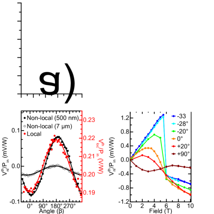
We show in Fig. 8b) and Fig. 8c) the local SSE (red) and NL-SSE for two wire separations (see Appendix C) for a fixed magnetic field of and respectively.
Alongside the experimental data points, we fit with a function, where the angular symmetry comes from the detection mechanism relying on the inverse spin Hall effect [3, 15].
A magnetic field of is below the spin-flop field at this temperature [28, 29].
There is then correspondingly no significant field induced magnetization due to the low magnetic field and we observe no local spin Seebeck signal.
However, we observe a clear non-local signal that follows the expected signal from the spin Seebeck effect, where we find a maximum for .
Looking above the spin-flop field (but below the Dzyaloshinskii-Moriya induced spin reorientation) [29, 28] at , a significant local SSE now appears but with the minimum (maximum) closer to the magnetic field lying in-plane than parallel to the easy-axis itself.
This maximum comes from the field induced magnetization appearing parallel to .
Looking at the non-local signal though, there is a phase shift between the local and non-local signals, with the minimum (maximum) in the non-local signal occurring for (.
Instead of fixing the magnitude of , we can fix the value of and probe the NL-SSE as a function of the magnetic field which we show in Fig. 8d).
The most significant signal appears for a magnetic field parallel to the easy-axis at .
We observe a linear increase of the observed signal with a sharp, sudden change of sign at the spin-flop field.
The transition becomes smoother with increasing angle, with the shape of the signal even changing sign when the magnetic field is applied completely out of the sample plane.
With an out-of-plane component of , we note that there may also be contributions from other thermo-electric effects such as the Righi-Leduc effect [58], but we would anticipate these to appear with a linear dependence on the applied magnetic field.
We can additionally probe the non-local spin Seebeck for the geometry discussed in Sec. III for a magnetic field applied at different angles in the plane perpendicular to . In the main text, we observe a significant transport signal perpendicular to the antiferromagnetic easy-axis. Unlike the geometry above, there is no component of the magnetization parallel to the transport direction for any magnitude of the applied field [see Fig. 5]. We show in Fig. 9b) the NL-SSE for different angles between and the easy-axis. We resolve that when the angle between the two is close to , we observe an increasing signal from until the spin-flop field, where a sharp transition results in a small, finite but field-independent voltage. Given the absence of a magnetization, this signal results purely from the transport of thermally excited magnons by the antiferromagnetic Néel vector.
Appendix E Local spin Seebeck signal for wires parallel to the easy-axis
We record the local spin Seebeck signal for the geometry discussed in Fig. 3, which we show in Fig. 10 for several temperatures. We observe no significant response as a function of the applied field even close to or above the spin-flop field.
Acknowledgements.
A.R. and M.K. acknowledge support from the Graduate School of Excellence Materials Science in Mainz (DFG/GSC 266). A.R. and M.K. also acknowledge support from both MaHoJeRo (DAAD Spintronics network, project numbers 57334897 and 57524834) and SPIN+X (DFG SFB TRR 173, projects A01 and B02) and KAUST (OSR-2019-CRG8-4048.2). This work was supported by the Max Planck Graduate Center with the Johannes Gutenberg-Universität Mainz (MPGC). A. R., R. L., M.E., U. N. and M.K. acknowledge support from the DFG project number 423441604. R.L. acknowledges the European Union’s Horizon 2020 research and innovation programme under the Marie Skłodowska-Curie grant agreement FAST number 752195. This work has received funding from the European Union’s Horizon 2020 research and innovation programme under Grant Agreement No. 863155 (s-Nebula). L.S. acknowledges support by a Mercator fellowship of the DFG. A.D. and L.S. acknowledge the support provided by the Ministry of Innovation and the National Research, Development, and Innovation (NRDI) Office under Projects No. PD124380, PD134579, K131938 and through the NRDI Fund (TKP2020 IES, Grant No. BME-IE-NAT). Computing resources for the ab initio calculations were provided by Governmental Information Technology Development Agency’s (KIFÜ) cluster in Debrecen, Hungary.References
- Cornelissen et al. [2015] L. J. Cornelissen, J. Liu, R. A. Duine, J. B. Youssef, and B. J. Van Wees, Long-distance transport of magnon spin information in a magnetic insulator at room temperature, Nat. Phys. 11, 1022 (2015).
- Goennenwein et al. [2015] S. T. B. Goennenwein, R. Schlitz, M. Pernpeintner, K. Ganzhorn, M. Althammer, R. Gross, and H. Huebl, Non-local magnetoresistance in YIG/Pt nanostructures, Appl. Phys. Lett. 107, 172405 (2015).
- Lebrun et al. [2018] R. Lebrun, A. Ross, S. A. Bender, A. Qaiumzadeh, L. Baldrati, J. Cramer, A. Brataas, R. A. Duine, and M. Kläui, Tunable long-distance spin transport in a crystalline antiferromagnetic iron oxide, Nature 561, 222 (2018).
- Ross et al. [2020a] A. Ross, R. Lebrun, O. Gomonay, D. A. Grave, A. Kay, L. Baldrati, S. Becker, A. Qaiumzadeh, C. Ulloa, G. Jakob, F. Kronast, J. Sinova, R. Duine, A. Brataas, A. Rothschild, and M. Kläui, Propagation length of antiferromagnetic magnons governed by domain configurations, Nano Lett. 20, 306 (2020a).
- Han et al. [2020] J. Han, P. Zhang, Z. Bi, Y. Fan, T. S. Safi, J. Xiang, J. Finley, L. Fu, R. Cheng, and L. Liu, Birefringence-like spin transport via linearly polarized antiferromagnetic magnons, Nature Nanotech. 15, 563 (2020).
- Lebrun et al. [2020] R. Lebrun, A. Ross, O. Gomonay, V. Baltz, U. Ebels, A. L. Barra, A. Qaiumzadeh, A. Brataas, J. Sinova, and M. Kläui, Long-distance spin-transport across the Morin phase transition up to room temperature in the ultra-low damping -Fe2O3 antiferromagnet, Nat. Commun. 11, 6331 (2020).
- Vaidya et al. [2020] P. Vaidya, S. A. Morley, J. Van Tol, Y. Liu, R. Cheng, A. Brataas, D. Lederman, and E. Del Barco, Subterahertz spin pumping from an insulating antiferromagnet, Science 368, 160 (2020).
- Li et al. [2020] J. Li, C. B. Wilson, R. Cheng, M. Lohmann, M. Kavand, W. Yuan, M. Aldosary, N. Agladze, P. Wei, M. S. Sherwin, and J. Shi, Spin current from sub-terahertz-generated antiferromagnetic magnons, Nature 578, 70 (2020).
- Boventer et al. [2021] I. Boventer, H. T. Simensen, A. Anane, M. Kläui, A. Brataas, and R. Lebrun, Room temperature antiferromagnetic resonance and inverse spin-hall voltage in canted antiferromagnets (2021), arXiv:2103.16872 [cond-mat.mes-hall] .
- Wu et al. [2016] S. M. Wu, W. Zhang, A. Kc, P. Borisov, J. E. Pearson, J. S. Jiang, D. Lederman, A. Hoffmann, and A. Bhattacharya, Antiferromagnetic spin Seebeck effect, Phys. Rev. Lett. 116, 097204 (2016).
- Reitz et al. [2020] D. Reitz, J. Li, W. Yuan, J. Shi, and Y. Tserkovnyak, Spin Seebeck effect near the antiferromagnetic spin-flop transition, Phys. Rev. B 102, 020408 (2020).
- Rezende et al. [2018] S. M. Rezende, A. Azevedo, and R. L. Rodríguez-Suárez, Magnon diffusion theory for the spin Seebeck effect in ferromagnetic and antiferromagnetic insulators, J. Phys. D: Appl. Phys. 51, 174004 (2018).
- Seki et al. [2015] S. Seki, T. Ideue, M. Kubota, Y. Kozuka, R. Takagi, M. Nakamura, Y. Kaneko, M. Kawasaki, and Y. Tokura, Thermal generation of spin current in an antiferromagnet, Phys. Rev. Lett. 115, 266601 (2015).
- Li et al. [2019] J. Li, Z. Shi, V. H. Ortiz, M. Aldosary, C. Chen, V. Aji, P. Wei, and J. Shi, Spin Seebeck effect from antiferromagnetic magnons and critical spin fluctuations in epitaxial FeF2 films, Phys. Rev. Lett. 122, 217204 (2019).
- Sinova et al. [2015] J. Sinova, S. O. Valenzuela, J. Wunderlich, C. H. Back, and T. Jungwirth, Spin Hall effects, Rev. Mod. Phys. 87, 1213 (2015).
- Cramer et al. [2019] J. Cramer, L. Baldrati, A. Ross, M. Vafaee, R. Lebrun, and M. Kläui, Impact of electromagnetic fields and heat on spin transport signals in Y3Fe5O12, Phys. Rev. B 100, 094439 (2019).
- Baltz et al. [2018] V. Baltz, A. Manchon, M. Tsoi, T. Moriyama, T. Ono, and Y. Tserkovnyak, Antiferromagnetic spintronics, Rev. Mod. Phys. 90, 015005 (2018).
- Shiomi et al. [2017] Y. Shiomi, R. Takashima, D. Okuyama, G. Gitgeatpong, P. Piyawongwatthana, K. Matan, T. J. Sato, and E. Saitoh, Spin Seebeck effect in the polar antiferromagnet -Cu2V2O7, Phys. Rev. B 96, 180414 (2017).
- Cornelissen and Van Wees [2016] L. J. Cornelissen and B. J. Van Wees, Magnetic field dependence of the magnon spin diffusion length in the magnetic insulator yttrium iron garnet, Phys. Rev. B 93, 20403(R) (2016).
- Yuan et al. [2018] W. Yuan, Q. Zhu, T. Su, Y. Yao, W. Xing, Y. Chen, Y. Ma, X. Lin, J. Shi, R. Shindou, X. C. Xie, and W. Han, Experimental signatures of spin superfluid ground state in canted antiferromagnet Cr2O3 via nonlocal spin transport, Sci. Adv. 4, eaat1098 (2018).
- Xing et al. [2019] W. Xing, L. Qiu, X. Wang, Y. Yao, Y. Ma, R. Cai, S. Jia, X. C. Xie, and W. Han, Magnon transport in quasi-two-dimensional van der Waals antiferromagnets, Phys. Rev. X 9, 011026 (2019).
- Hoogeboom and van Wees [2020] G. R. Hoogeboom and B. J. van Wees, Non-local spin Seebeck effect in the bulk easy-plane antiferromagnet NiO, Phys. Rev. B 102, 214415 (2020).
- Muduli et al. [2021] P. Muduli, R. Schlitz, T. Kosub, R. Hübner, A. Erbe, D. Makarov, and S. T. B. Goennenwein, Local and nonlocal spin Seebeck effect in lateral Pt-Cr2O3-Pt devices at low temperatures, APL Mater. 9, 021122 (2021).
- Bender et al. [2017] S. A. Bender, H. Skarsvåg, A. Brataas, and R. A. Duine, Enhanced Spin Conductance of a Thin-Film Insulating Antiferromagnet, Phys. Rev. Lett. 119, 056804 (2017).
- Hoogeboom et al. [2021] G. R. Hoogeboom, G.-J. N. S. Nicolaas, A. Alexander, O. Kuschel, J. Wollschläger, I. Ennen, B. J. van Wees, and T. Kuschel, Role of nio in the nonlocal spin transport through thin nio films on , Phys. Rev. B 103, 144406 (2021).
- Wimmer et al. [2021] T. Wimmer, J. Gückelhorn, S. Wimmer, S. Mankovsky, H. Ebert, M. Opel, S. Geprägs, R. Gross, H. Huebl, and M. Althammer, Low temperature suppression of the spin nernst angle in pt (2021), arXiv:2103.12697 [cond-mat.mtrl-sci] .
- Fink [1964] H. J. Fink, Resonance line shapes of weak ferromagnets of the -Fe2O3 and NiF2 type, Phys. Rev. 133, A1322 (1964).
- Lebrun et al. [2019] R. Lebrun, A. Ross, O. Gomonay, S. A. Bender, L. Baldrati, F. Kronast, A. Qaiumzadeh, J. Sinova, A. Brataas, R. A. Duine, and M. Kläui, Anisotropies and magnetic phase transitions in insulating antiferromagnets determined by a Spin-Hall magnetoresistance probe, Commun. Phys. 2, 50 (2019).
- Morrison et al. [1973] B. R. Morrison, A. H. Morrish, and G. J. Troup, High-field antiferromagnetic resonance in -Fe2O3, Phys. Status Solidi (B) 56, 183 (1973).
- Ross et al. [2020b] A. Ross, R. Lebrun, C. Ulloa, D. A. Grave, A. Kay, L. Baldrati, F. Kronast, S. Valencia, A. Rothschild, and M. Kläui, Structural sensitivity of the spin Hall magnetoresistance in antiferromagnetic thin films, Phys. Rev. B 102, 094415 (2020b).
- Morin [1950] F. J. Morin, Magnetic susceptibility of -Fe2O3 and -Fe2O3 with added titanium, Phys. Rev. 78, 819 (1950).
- Flebus [2019] B. Flebus, Chemical potential of an antiferromagnetic magnon gas, Phys. Rev. B 100, 064410 (2019).
- Manchon [2017] A. Manchon, Spin Hall magnetoresistance in antiferromagnet/normal metal bilayers, Phys. Status Solidi - Rapid Res. Lett. 11, 1600409 (2017).
- Baldrati et al. [2018] L. Baldrati, A. Ross, T. Niizeki, C. Schneider, R. Ramos, J. Cramer, O. Gomonay, M. Filianina, T. Savchenko, D. Heinze, A. Kleibert, E. Saitoh, J. Sinova, and M. Kläui, Full angular dependence of the spin Hall and ordinary magnetoresistance in epitaxial antiferromagnetic NiO(001)/Pt thin films, Phys. Rev. B 98, 024422 (2018).
- Hoogeboom et al. [2017] G. R. Hoogeboom, A. Aqeel, T. Kuschel, T. T. M. Palstra, and B. J. van Wees, Negative spin Hall magnetoresistance of Pt on the bulk easy-plane antiferromagnet NiO, Appl. Phys. Lett. 111, 052409 (2017).
- Fischer et al. [2018] J. Fischer, O. Gomonay, R. Schlitz, K. Ganzhorn, N. Vlietstra, M. Althammer, H. Huebl, M. Opel, R. Gross, S. T. B. Goennenwein, and S. Geprägs, Spin Hall magnetoresistance in antiferromagnet/heavy-metal heterostructures, Phys. Rev. B 97, 014417 (2018).
- Geprägs et al. [2020] S. Geprägs, M. Opel, J. Fischer, O. Gomonay, P. Schwenke, M. Althammer, H. Huebl, and R. Gross, Spin hall magnetoresistance in antiferromagnetic insulators, Journal of Applied Physics 127, 243902 (2020), https://doi.org/10.1063/5.0009529 .
- Shan et al. [2016] J. Shan, L. J. Cornelissen, N. Vlietstra, J. Ben Youssef, T. Kuschel, R. A. Duine, and B. J. van Wees, Influence of yttrium iron garnet thickness and heater opacity on the nonlocal transport of electrically and thermally excited magnons, Phys. Rev. B 94, 174437 (2016).
- Kohno et al. [2021] R. Kohno, N. Thiery, K. An, P. Noel, L. Vila, V. V. Naletov, N. Beaulieu, J. B. Youssef, G. de Loubens, and O. Klein, Enhancement of yig —pt spin conductance by local joule annealing, Appl. Phys. Lett. 118, 032404 (2021).
- Wimmer et al. [2020] T. Wimmer, A. Kamra, J. Gückelhorn, M. Opel, S. Geprägs, R. Gross, H. Huebl, and M. Althammer, Coherent control of magnonic spin transport in an antiferromagnetic insulator, Phys. Rev. Lett. 125, 247204 (2020).
- Kamra et al. [2020] A. Kamra, T. Wimmer, H. Huebl, and M. Althammer, Antiferromagnetic magnon pseudospin: Dynamics and diffusive transport, Phys. Rev. B 102, 174445 (2020).
- Ross et al. [2020c] A. Ross, R. Lebrun, L. Baldrati, A. Kamra, O. Gomonay, S. Ding, F. Schreiber, D. Backes, F. Maccherozzi, D. A. Grave, A. Rothschild, J. Sinova, and M. Kläui, An insulating doped antiferromagnet with low magnetic symmetry as a room temperature spin conduit, Appl. Phys. Lett. 117, 242405 (2020c).
- Cramer et al. [2018] J. Cramer, U. Ritzmann, B.-W. Dong, S. Jaiswal, Z. Qiu, E. Saitoh, U. Nowak, and M. Kläui, Spin transport across antiferromagnets induced by the spin Seebeck effect, J. Phys. D: Appl. Phys. 51, 144004 (2018).
- Kehlberger et al. [2015] A. Kehlberger, U. Ritzmann, D. Hinzke, E.-J. Guo, J. Cramer, G. Jakob, M. C. Onbasli, D. H. Kim, C. A. Ross, M. B. Jungfleisch, B. Hillebrands, U. Nowak, and M. Kläui, Length Scale of the Spin Seebeck Effect, Phys. Rev. Lett. 115, 096602 (2015).
- Samuelsen and Shirane [1970] E. J. Samuelsen and G. Shirane, Inelastic neutron scattering investigation of spin waves and magnetic interactions in -Fe2O3, Phys. Status Solidi (B) 42, 241 (1970).
- Samuelsen et al. [1970] E. Samuelsen, M. Hutchings, and G. Shirane, Inelastic neutron scattering investigation of spin waves and magnetic interactions in Cr2O3, Physica 48, 13 (1970).
- Nowak [2007] U. Nowak, Classical spin models, in Handbook of Magnetism and Advanced Magnetic Materials, Vol. 2, edited by H. Kronmüller and S. Parkin (John Wiley & Sons, Ltd, Chichester, 2007) available under http://nbn-resolving.de/urn:nbn:de:bsz:352-opus-92390.
- Landau and Lifshitz [1935] L. Landau and E. Lifshitz, On the theory of the dispersion of magnetic permeability in ferromagnetic bodies, Phys. Z. Sowjetunion 8, 153 (1935).
- Gilbert [1955] T. L. Gilbert, A lagrangian formulation of the gyromagnetic equation of the magnetic field, Physical Review 100, 1243 (1955).
- Gilbert [2004] T. L. Gilbert, A phenomenological theory of damping in ferromagnetic materials, IEEE Transactions on Magnetics 40, 3443 (2004).
- Brown Jr. [1963] W. F. Brown Jr., Thermal fluctuations of a single-domain particle, Phys. Rev. 130, 1677 (1963).
- Morrish [1994] A. H. Morrish, Canted Antiferromagnetism: Hematite (World Scientific Publishing, Singapore, New Jersey, London, Hong Kong, 1994).
- Ritzmann et al. [2014] U. Ritzmann, D. Hinzke, and U. Nowak, Propagation of thermally induced magnonic spin currents, Phys. Rev. B 89, 024409 (2014).
- Ritzmann et al. [2017] U. Ritzmann, D. Hinzke, and U. Nowak, Thermally induced magnon accumulation in two-sublattice magnets, Phys. Rev. B 95, 054411 (2017).
- Zabloudil et al. [2005] J. Zabloudil, R. Hammerling, L. Szunyogh, and P. Weinberger, Electron Scattering in Solid Matter, Springer Series in Solid-State Sciences, Vol. 147 (Springer, Heidelberg, 2005).
- Deák et al. [2011] A. Deák, L. Szunyogh, and B. Ujfalussy, Thickness-dependent magnetic structure of ultrathin Fe/Ir(001) films: From spin-spiral states toward ferromagnetic order, Phys. Rev. B 84, 224413 (2011).
- Szunyogh et al. [2011] L. Szunyogh, L. Udvardi, J. Jackson, U. Nowak, and R. Chantrell, Atomistic spin model based on a spin-cluster expansion technique: Application to the IrMn3/Co interface, Phys. Rev. B 83, 024401 (2011).
- Thiery et al. [2018] N. Thiery, V. V. Naletov, L. Vila, A. Marty, A. Brenac, J.-F. Jacquot, G. de Loubens, M. Viret, A. Anane, V. Cros, J. Ben Youssef, N. Beaulieu, V. E. Demidov, B. Divinskiy, S. O. Demokritov, and O. Klein, Electrical properties of epitaxial yttrium iron garnet ultrathin films at high temperatures, Phys. Rev. B 97, 064422 (2018).