Present address:]AWS Center for Quantum Computing, Pasadena, CA, USA
Hardware-Efficient, Fault-Tolerant Quantum Computation with Rydberg Atoms
Abstract
Neutral atom arrays have recently emerged as a promising platform for quantum information processing. One important remaining roadblock for the large-scale application of these systems is the ability to perform error-corrected quantum operations. To entangle the qubits in these systems, atoms are typically excited to Rydberg states, which could decay or give rise to various correlated errors that cannot be addressed directly through traditional methods of fault-tolerant quantum computation. In this work, we provide the first complete characterization of these sources of error in a neutral-atom quantum computer and propose hardware-efficient, fault-tolerant quantum computation schemes that mitigate them. Notably, we develop a novel and distinctly efficient method to address the most important errors associated with the decay of atomic qubits to states outside of the computational subspace. These advances allow us to significantly reduce the resource cost for fault-tolerant quantum computation compared to existing, general-purpose schemes. Our protocols can be implemented in the near-term using state-of-the-art neutral atom platforms with qubits encoded in both alkali and alkaline-earth atoms.
I Introduction
Neutral atom systems have recently emerged as a promising platform for quantum information processing. While the exceptional coherence times of their ground states enable long-lived quantum memories, fast, high-fidelity quantum operations can be achieved by individually addressing atoms with laser pulses and coupling them to highly-excited Rydberg states Jaksch et al. (2000); Lukin et al. (2001); Saffman et al. (2010). Furthermore, large numbers of individual neutral atoms can be deterministically arranged with arbitrary geometry in two- and three-dimensional systems Barredo et al. (2016); Ebadi et al. (2020); Barredo et al. (2018, 2020). Recent experiments have demonstrated quantum manipulation in large arrays of atoms for applications ranging from quantum computing to quantum simulations and quantum metrology Bernien et al. (2017); Levine et al. (2018); Labuhn et al. (2016); Maller et al. (2015); Levine et al. (2019); Graham et al. (2019); Kim et al. (2018); Keesling et al. (2019); Omran et al. (2019); Semeghini et al. (2021); Bluvstein et al. (2021a). Several latest advances allowing for the dynamic reconfiguration of atoms have even led to realization of logical qubits encoded in color, surface, or toric codes, which is a first step to performing quantum error correction (QEC) on neutral atom platforms Bluvstein et al. (2021a).
While current experiments are already demonstrating a remarkable level of quantum control, experimental imperfections such as Rydberg state decay will eventually limit the depth of accessible quantum operations. To scale up the computation size, it is therefore essential to consider QEC protocols Nielsen and Chuang (2000). In particular, such protocols should be fault-tolerant and protect against the key sources of errors occurring within any of the computation, error detection, and encoding and decoding stages. Multiple fault-tolerant protocols have been proposed for generic quantum platforms Shor (1996); Kitaev (2003); Gottesman (2010); Yoder and Kim (2017); Chao and Reichardt (2018a, b); Reichardt (2018); Chamberland and Beverland (2018); Chao and Reichardt (2020), but they do not address certain errors present in Rydberg atom setups. Indeed, Rydberg-atom QEC seems to face a daunting challenge at first glance: Rydberg states could decay into multiple other states, which not only results in leakage errors out of the computational space, but could also give rise to high-weight correlated errors from ensuing undesired blockade effects. Motivated by these considerations, we investigate the effects of these intrinsic errors. Remarkably, by utilizing the unique capabilities of Rydberg systems and the structure of the error model, we can design hardware-efficient, fault-tolerant quantum computation (FTQC) schemes that address these errors despite the aforementioned challenges (Figure 1). This tailored FTQC approach can even be much more resource efficient than generic proposals Michael et al. (2016); Chamberland et al. (2020) (Tables 1 and 2), which often require a larger number of qubits and quantum operations with smaller threshold error than what is achievable in near-term experiments to perform non-Clifford logical operations, either directly Yoder et al. (2016); Chao and Reichardt (2018b) or by using state distillation Shor (1996); Bravyi and Kitaev (2005). The high overhead associated with such protocols is why experimental demonstrations of QEC have thus far been limited to only one or two logical qubits Nigg et al. (2014); Rosenblum et al. (2018); Campagne-Ibarcq et al. (2020); de Neeve et al. (2020); Egan et al. (2021).
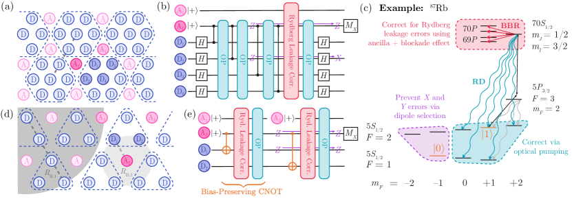
In this work, we first provide a detailed understanding, from the QEC perspective, of the errors arising from the finite lifetime of the Rydberg state or from imperfections in Rydberg laser pulses. We then show that nine atoms—seven data qubits and two ancilla qubits—are sufficient to encode each logical qubit fault-tolerantly based on the seven-qubit Steane code Steane (1996); we demonstrate how a universal set of fault-tolerant quantum operations can be performed. For atomic species with sufficiently large nuclear spin and high-fidelity ground-state operations, we show that quantum computation with leading-order fault-tolerance can be achieved even using a simple three-atom repetition code 111The three-qubit repetition code cannot correct any Pauli- errors, so it cannot be used for FTQC in typical setups. However, because the error model for Rydberg-atom setups does not contain any Pauli- errors at the leading order (as shown in Section III), the repetition code is applicable in these platforms. We thus use the term “leading-order fault-tolerance” when describing our Ryd-3 protocol to emphasize this point explicitly.. We find that both the seven-atom and three-atom codes can be implemented on scalable geometries with atoms placed in a triangular lattice configuration (Figure 1a,d), allowing for their demonstration and study in near-term experiments.
Our work provides an important advance over prior methods by introducing a novel and distinctly efficient approach to address the leakage of qubits out of the computational subspace. For traditional QEC proposals, such leakage is one of the most difficult and costly types of errors to detect and address, making it unfavorable to encode qubits in large multi-level systems such as neutral atoms. Our method to address these leakage errors makes use of techniques based on optical pumping, such that the multi-level structure of each atom can be utilized as part of the redundancy required for QEC. While we focus on neutral atom-based quantum information processors, these techniques are adaptable to many other hardware platforms—for example, they could also greatly facilitate the correction of leakage-type errors in superconducting qubits or trapped ions. For the Rydberg-atom systems we study, we design a method that even converts all leading-order errors to Pauli- type errors (Figure 1c), which then allows us to develop particularly efficient FTQC protocols.
The manuscript is organized as follows: we begin in Section II by outlining the key insights and main results of this work. A detailed analysis of the error channels in the Rydberg system is presented in Section III. Under this realistic error model, we design FTQC schemes based on the seven-qubit Steane code in Section IV. Furthermore, by utilizing atomic species with high nuclear spin, we develop an alternative, leading-order fault-tolerant protocol in Section V based on a simple repetition code. We then show in Section VI how the key ingredients of our proposals can be implemented in near-term experiments. Finally, we present conclusions and outlook in Section VII.
II Overview of Main Results
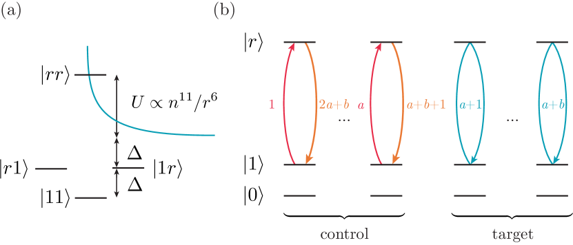
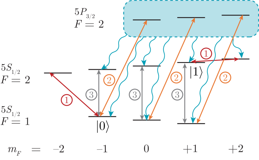
We consider neutral atoms in a static magnetic field . Due to the nonzero nuclear spin , the electronic ground state manifold consists of many sub-levels split by hyperfine coupling and a finite field. These levels exhibit remarkably long lifetimes, making them particularly good candidates for encoding qubits (or more generally, qudits) for quantum information processing. Furthermore, although neutral atoms in ground electronic states are effectively non-interacting, entangling gates between nearby atoms can be performed by coupling one of the qubit states (e.g. ) to a Rydberg state with large , which exhibits strong van der Waals interactions (Figure 2a). Under certain conditions, these interactions can be interpreted effectively as a blockade constraint prohibiting simultaneous Rydberg population within a blockade radius . These can be leveraged to perform, for example, fast multi-control, multi-target phase gates (sometimes also referred to as “collective gates”), which are related to the standard gates upon conjugating all control qubits and the first target qubit by Pauli- gates Jaksch et al. (2000); Isenhower et al. (2011); Levine et al. (2019); this is achieved by applying individually addressed, resonant and pulses between the qubit state and the Rydberg state (Figure 2b). Such an operation is also related to the gate by single-qubit unitaries and has been demonstrated in recent experiments for small Levine et al. (2019).
While this procedure provides an efficient scheme to entangle two or several atoms, for large-scale quantum computations, the finite lifetime of Rydberg states presents an important source of error even if the rest of the experimental setup is perfect. This lifetime is determined by several contributions. First, interactions with blackbody photons can induce transitions from the state to nearby Rydberg states of higher or lower energy; such errors are subsequently referred to as blackbody radiation-induced (BBR) errors. Second, spontaneous emission of an optical frequency photon can result in radiative decay (RD) to a low-lying state, which will quickly relax into the ground state manifold. In addition, if a multi-photon Rydberg excitation scheme is used for the Rydberg pulses, another intrinsic source of error during Rydberg gates is photon scattering from an intermediate state. These error channels are illustrated in Figure 1c.
For the purposes of QEC, these errors can be formally described as follows (see Section III): BBR errors give rise to quantum jumps from the qubit state to Rydberg states (corresponding to a leakage error), as well as Pauli- errors within the qubit manifold, while RD and intermediate state scattering may also result in quantum jumps from to the Rydberg state or other hyperfine ground states. The relative error probabilities are determined by selection rules and branching ratios. In addition to these intrinsic errors, we also study the errors in the experimental setup such as Rydberg pulse imperfections or finite atomic temperature. We find that these experimental errors fall within a subset of the RD error model and can therefore also be addressed using our techniques. We note that, throughout this work, we assume the rotations within the hyperfine manifold have much higher fidelity than the Rydberg pulses, as is typically the case. Such errors can also be suppressed to high orders by using existing experimental methods such as composite pulse sequences or by incorporating traditional QEC techniques such as concatenation.
II.1 Reduction to Pauli- errors
To protect against the errors mentioned above, three critical observations are used (see Figure 1c). First, we note that quantum jumps from to Rydberg states associated with BBR can be detected via the Rydberg blockade effect by using a nearby ancilla qubit, and subsequently converted to a Pauli- type error by ejecting the Rydberg atom and replacing it with a fresh atom prepared in the state Bluvstein et al. (2021a). Second, quantum jumps from to ground state sublevels outside the qubit subspace can be corrected via optical pumping techniques. This is particularly efficient as it does not require any qubit measurement for feed-forward corrections, unlike traditional proposals for correcting leakage errors Auger et al. (2017). Third, for atomic species with large enough nuclear spin, dipole selection rules prevent a stretched Rydberg state from decaying to certain ground state sublevels. By making use of this multi-level structure of neutral atoms along with the high-fidelity manipulations of hyperfine states, we can ensure that RD and intermediate state scattering errors do not result in transitions, thereby eliminating and type errors from the error model. This reduction of error types can significantly alleviate the resource requirement for FTQC.
| 2-qubit gates | 3-qubit gates | Ancillas | |
| 7-qubit flagged Chao and Reichardt (2018a) | 36 (48) | 0 | 2 |
| 15-qubit flagged Chao and Reichardt (2018a) | 80 (112) | 0 | 2 |
| Ryd-7 | 24 (36) | 0 | 2 |
| Ryd-3 | 8 (16) | 4 (8) | 4 |
| 2-qubit gates | 3-qubit gates | Ancillas | |
| Yoder, Takagi, and Chuang Yoder et al. (2016) (CCZ) | 162 | 21 | 72 |
| Chao and Reichardt Chao and Reichardt (2018b) (CCZ) | 1352 (1416) | 84 | 4 |
| Ryd-7 (CCZ) | 0 (78) | 27 (29) | 2 |
| Ryd-3 (CCZ) | 0 (18) | 27 (27) | 4 |
| Ryd-3 (H) | 20 (28) | 53 (57) | 10 |
II.2 Fault-tolerant protocols
We now describe two FTQC protocols to address these intrinsic errors in neutral Rydberg atom platforms. The first is based on the seven-qubit Steane code Steane (1996), while the second uses the three-qubit repetition code; the latter is more compact and efficient, but has additional experimental requirements such as control over multiple Rydberg states and more complex encoding of logical operations. To realize the seven-qubit code (Ryd-7), we notice that logical state preparation, stabilizer measurements, and a universal set of logical gates (Hadamard and Toffoli Shi (2003)) can be implemented using only controlled-phase (CZ) or controlled-controlled-phase (CCZ) gates, up to single-qubit unitaries at the beginning and end of the operation. For example, while the stabilizer measurements are typically presented as a sequence of CNOT gates between the data atoms and an ancilla atom, these CNOT gates can be constructed by conjugating a CZ gate with Hadamard gates on the target qubit. By mapping each Rydberg gate error to a Pauli- error, we therefore ensure that it will commute with all subsequent entangling gates in the logical operation or stabilizer measurement, so it does not spread to other qubits (Figure 1b). The resulting single-qubit or error can be corrected by the seven-qubit code in a subsequent round of QEC. This eliminates the need for “flag qubits,” which are otherwise necessary to prevent spreading of errors as discussed in Ref. Chao and Reichardt (2018a, b). To further reduce resource costs for experimental implementation, we make additional use of the structure of the Rydberg error model, stabilizer measurement circuits, and logical operations of the seven-qubit code. For instance, one of our key findings is that leakage errors into other Rydberg states do not need to be corrected after every Rydberg gate, but can be postponed to the end of a stabilizer measurement (e.g. Figure 1b). This allows us to minimize the number of intermediate measurements necessary for each FTQC component, which is typically a limiting factor in state-of-the-art neutral atom experiments.
The simplified error model introduced by conversion of all Rydberg gate errors to Pauli- errors motivates us to use the three-qubit repetition code instead of the seven-qubit code to design a leading-order fault-tolerant protocol (Ryd-3). In this case, the stabilizer measurement circuits are also comprised of CNOT gates on data atoms controlled by the ancilla. However, the implementation of each CNOT must be modified: when a CZ gate is conjugated by Hadamard gates as in Figure 1b, a Pauli- type error that occurs during the CZ gate will be converted to a Pauli- error after the Hadamard. Such an error can no longer be corrected by the repetition code. Additional errors, such as radiative decay of a control qubit prior to manipulation of the target qubit, can lead to error spreading and correlated errors.
These errors can be addressed via a protocol to directly implement CNOT gates in a bias-preserving way, such that these implementations will not generate any Pauli- and errors to leading order (Figures 7 and 8). Our protocol makes use of the rich multilevel structure of atoms with large nuclear spin (, e.g. 85Rb, 133Cs, 87Sr, …), as well as additional Rydberg states for shelving. Furthermore, we leverage the fact that pulses between certain (i.e. hyperfine) levels can be performed with very high fidelity, so that leading-order errors involve only Rydberg state decay or Rydberg pulse imperfections. This assumption is particularly important, as Ref. Guillaud and Mirrahimi (2019) shows a no-go theorem stating that a bias-preserving CNOT gate cannot be implemented in any qudit system with a finite number of levels without such structure in the error model. To circumvent this, our pulse sequence directly implements a hyperfine Pauli- gate on the target qubit only if a nearby Rydberg atom is present (without the need for subsequent Hadamard gates), and we show that errors during this sequence can all be mapped to Pauli- errors. Additionally, correlated errors due to control-atom decay can be prevented by using multiple control atoms, such that if one atom decays, the remaining atom(s) still ensure proper gate operation on the target atom. This bias-preserving CNOT protocol can be directly generalized to implement a bias-preserving Toffoli operation, enabling a leading-order fault-tolerant implementation of each operation of the three-atom repetition code. Throughout the manuscript, we use the term “leading-order fault-tolerance” in referring to the Ryd-3 protocol as our framework does not inherently address all single-qubit errors, but existing experimental techniques such as composite pulse sequences can be used in conjunction with our protocol to suppress such errors to higher orders (see Section III.4).
Upon comparing our protocols with existing, general-purpose FTQC proposals, we find that the number of required physical qubits and gates for both of our approaches is dramatically reduced (Tables 1, 2). For example, as seen in Table 2, performing the highest-cost operation from our logical gate set, our Ryd-7 protocol requires only 2 ancilla qubits compared with 72 ancillas in Yoder, Takagi, and Chuang Yoder et al. (2016). Likewise, Ryd-7 uses at most 60 2-qubit gates (when errors are detected) to perform this logical operation, instead of 1416 gates as in Chao and Reichardt Chao and Reichardt (2018b). Such a significant reduction is possible for our protocols because we leverage both the special structure of the error model and the unique capabilities of Rydberg setups.
Several aspects of the comparison above should be considered. Specifically, we note that certain single-qubit errors addressed in Refs. Yoder et al. (2016); Chao and Reichardt (2018b) cannot be corrected in our protocols (e.g. Pauli- errors arising from rotations in the hyperfine manifold). However, we emphasize that Refs. Yoder et al. (2016); Chao and Reichardt (2018b) also did not consider additional types of errors such as leakage errors which are corrected by our protocol. Indeed, incorporating leakage correction would further increase the resource cost for the earlier proposals considerably. As such, Tables 1, 2 must be interpreted as a comparison of the cost ensuring fault-tolerance against the leading-order sources of error in a given setup. In the case of Refs. Yoder et al. (2016); Chao and Reichardt (2018b), these errors include all single-qubit Pauli errors but not leakage errors, while in Rydberg systems, one must address leakage errors at leading order but can neglect certain single-qubit errors.
II.3 Towards experimental implementation
For scalable implementation of our FTQC protocols, it is important to consider the geometrical placement of atoms. In addition, because Rydberg entangling gates can only be implemented between atoms within the blockade radius , each protocol defines a minimum value of (in units of , which is the smallest atom-atom separation). We find that both the Ryd-7 and Ryd-3 protocols can be implemented naturally when the atoms are placed on the vertices of a triangular lattice as shown in Figure 1a,d. For both protocols, the required Rydberg gates can be implemented when the blockade radius ( for Ryd-7, or the larger radius for Ryd-3) is greater than , an interaction range which has already been demonstrated in recent experiments Bernien et al. (2017). This requirement can be further reduced in both cases if it is possible to move atoms in between certain operations while preserving the coherence of hyperfine ground states, a capability which has been recently realized Bluvstein et al. (2021a).
Each component of our FTQC schemes can be implemented in near-term experiments. For neutral alkali-atom systems, recent experiments have already achieved high-fidelity control and entanglement leading to remarkable demonstrations of quantum simulations and computations Levine et al. (2018, 2019); Saffman et al. (2010). The near-deterministic loading of atoms into lattice structures as shown in Figure 1 has already been realized in two and three dimensions Barredo et al. (2016); Ebadi et al. (2020); Barredo et al. (2018, 2020).
To perform QEC in our protocol, an important requirement is the ability to measure individual qubits and/or detect Rydberg population while preserving coherence in nearby atoms, such that feed-forward correction can be performed. Several approaches for performing fast measurements of individual qubit states in selected atoms can be realized. For example, these selected atoms can be moved into a “readout zone” where their qubit state can be rapidly detected via fast, resonant photon scattering on a cycling transition. Alternatively, one could use arrays with two species (such as two isotopes of the same atom or two different atomic species), where the data atoms are encoded in one atomic species and ancilla atoms are encoded in another species that can be easily measured Zeng et al. (2017); Singh et al. (2021). Finally, the fast detection of Rydberg states has been recently demonstrated in small atomic ensembles using Rydberg electromagnetically induced transparency (EIT) Xu et al. (2021). These could be integrated with the tweezer array platforms currently used for quantum information processing. In these EIT-based procedures, the Rydberg blockade effect translates to clean signatures in the absorption spectrum, and the collectively enhanced Rabi frequency allows for ultrafast detection on a microsecond time scale Xu et al. (2021).
While we focus primarily on neutral alkali atoms in this work, significant developments have also been made using alkaline-earth atoms for Rydberg-based quantum computations Madjarov et al. (2020); Wilson et al. (2019). The clock transition in these atoms allows for high-fidelity qubit encodings, and the large nuclear spin in fermionic species is particularly advantageous for our protocols, so we conclude by discussing how our FTQC schemes can be generalized and applied to these experiments. More detailed experimental considerations are discussed in Section VI.
III Error Channels in Rydberg Atoms
In this section, we analyze dominant error mechanisms for quantum operations involving Rydberg atoms (Figure 1c). Because the predominant errors in single-qubit operations can be suppressed to high orders via composite pulse sequences Vandersypen and Chuang (2005); Bluvstein et al. (2021a), we may primarily focus on errors occurring during Rydberg-mediated entangling operations. The decay channels of the Rydberg states include blackbody radiation-induced (BBR) transitions and spontaneous radiative decay (RD) transitions to lower-lying states Beterov et al. (2009). Depending on the specific choice of atomic species, another source of error for Rydberg gates can be the scattering from an intermediate state if a two- or multi-photon excitation scheme is used; this is the case for excitation of 87Rb or 85Rb to Rydberg states Bernien et al. (2017). We will assume these effects are the predominant source of errors that occur during the entangling operations, and we consider contributions to the error model to leading order in the total error probability.
III.1 Error modeling for BBR transitions
When a BBR transition occurs on one of the atoms during an entangling gate, it signals that this atom has started in the state, since is not coupled to . Such a procedure corresponds to a ‘quantum jump’ as discussed in, for example, Ref. Carmichael (1993). The resulting state will predominantly be a nearby Rydberg state compatible with dipole selection rules. Due to the relatively long lifetimes of Rydberg states, we may assume that the atom will not decay again within the timescale of several Rydberg gate operations, as these would be higher-order processes. In this case, because the states are not de-excited in the ensuing operations, one serious consequence of BBR quantum jumps is that the remaining Rydberg operations on atoms within the interaction range will be affected by blockade, potentially resulting in multiple, correlated Pauli- type errors. Less intuitively, even if a quantum jump does not occur during the gate operation, the atom’s state is still modified due to evolution under a non-Hermitian Hamiltonian: it will be more likely that the atom started out in the state. More details on the theory of quantum jumps can be found in Ref. Carmichael (1993).
For the purposes of QEC, it is useful to express the decay channels in the Kraus operator form, where time evolution of a density operator is given by and the Kraus operators satisfy the completeness relation Preskill (1998). For the BBR error model, there will be one Kraus operator
| (1) |
for each possible final Rydberg state , where the proportionality constant is determined by the BBR transition rate from to (see Appendix A). In the absence of quantum jumps, the evolution is given by the Kraus map
| (2) |
where is the probability for a BBR transition to occur.
During entangling operations, these BBR errors can give rise to correlated errors. For example, in the Rydberg gates shown in Figure 2, a target qubit can only incur a BBR error if the control qubits were all in the state. Thus, for the gates shown in Figure 2, the possible correlated errors may involve one of the Kraus maps or occurring on one of the qubits, together with -type errors on some or all of the remaining qubits involved in that gate.
The rate of BBR transitions from a given Rydberg state to another specific state can be calculated from the Planck distribution of photons at the given temperature and the Einstein coefficient for the corresponding transition (see Ref. Beterov et al. (2009)). For 87Rb atoms excited to the Rydberg state, there are four dominant final states associated to these BBR errors (see Appendix A); these are illustrated in Figure 1c as red arrows. The total rate of BBR transitions summed over all possible final states is Cooke and Gallagher (1980)
| (3) |
where is Boltzmann’s constant, is the speed of light, and is the effective principal quantum number of the Rydberg state which determines its energy Saffman et al. (2010): . We note that the overall rate of BBR transitions can be suppressed by operating at higher or operating at cryogenic temperatures.
III.2 Error modeling for RD transitions
The spontaneous emission events corresponding to RD transitions can be modeled as quantum jumps involving the emission of an optical-wavelength photon. Unlike BBR, however, the resulting state will be a low-lying state, which will quickly decay back into the ground state manifold. For the stretched Rydberg state of 87Rb, the RD transitions are almost entirely two- or four-photon decay processes to one of the five states in the ground state manifold indicated by light blue arrows in Figure 1c (see Appendix A for the precise branching ratios). For the purpose of QEC, we will separately consider the cases of decay into the qubit state and decay into one of the other ground state sub-levels. Because the spontaneous emission event can occur anytime during the Rydberg laser pulse, the first type of decay can result in a final state which is a superposition of and . Upon averaging over all possible decay times during the entire pulse (see Appendix B), one finds that these errors can be modeled using a combination of -type errors and leakage into the state, with the Kraus operators
| (4) |
where , , and the proportionality constants depend on the probability for the atom to incur an RD transition to the state and the specific Rydberg pulse being performed.
At the same time, decay to one of the other ground state sublevels shown in Figure 1c leads to leakage out of the computational subspace as in the traditional QEC setting (without influencing Rydberg operations on neighboring atoms). That is, for each hyperfine state , we have a Kraus operator
| (5) |
where the proportionality constant depends on the probability for an RD transition and the branching ratio from to the specific state (see Appendix A). Note that due to dipole selection rules, the number of RD channels with non-negligible final state probability is minimized by choosing to couple the state to a so-called “stretched Rydberg state” for entangling gates 222 If, for example, we had instead chosen a Rydberg state with , there would be several additional final states in each case.. In particular, in this analysis, the decay into the qubit state is negligible to leading order. Such an event, corresponding to the Kraus operator (or equivalently, Pauli- and errors), is considered when we discuss methods to suppress residual errors in our protocols.
As in the BBR case, the absence of quantum jumps results in the atom’s population being shifted toward the state, which can be modeled using Pauli- errors. RD errors can also give rise to correlated errors when they occur during the primitive entangling gates illustrated in Figure 2. In this case, possible correlated errors may involve one of the aforementioned Kraus maps occurring on one of the qubits, together with Pauli- and/or errors on some or all of the remaining qubits involved in that gate.
While as noted above, the rate of BBR transitions depends upon the temperature and , the total RD rate is temperature-independent. Due to reduced overlap between the atomic orbitals, it scales as Löw et al. (2012). Comparing this with the scaling for the BBR decay rate, we see that while both error rates decrease for larger , BBR processes dominate for large , and RD processes dominate for smaller or very low .
III.3 Errors from intermediate state scattering
When multi-photon excitation is used to couple the state to the Rydberg state, scattering from an intermediate state can give rise to another important intrinsic source of error. By using -polarized light in the first step of the excitation and choosing the intermediate state to be a state with the lowest possible , the intermediate state scattering channels form a subset of the RD channels—they can only result in decay into the qubit state or two other hyperfine ground states, as shown in grey in Figure 1c 333If an intermediate state with higher is used, such as , this is still true to leading order; however, a (highly improbable) four-photon process could potentially lead to mixing between the qubit states and .. Thus, whenever intermediate state scattering is not explicitly mentioned in the following sections, we will assume it has been incorporated with RD errors. We also note that this error rate can be suppressed by increasing intermediate laser detuning in the multi-photon transition, while also increasing laser power.
III.4 Experimental imperfections
While BBR, RD, and intermediate state scattering processes constitute the dominant errors for Rydberg-mediated collective gates, it is also important to consider other forms of error, such as technical imperfections in the experimental setup. As discussed in Refs. Bernien et al. (2017); Levine et al. (2018); Bluvstein et al. (2021a), the most significant errors of this kind are atom loss and fluctuations in laser phase, intensity, and frequency. The Rydberg laser fluctuations can all be modeled using Pauli- errors and leakage into the state, so these errors can be addressed together with the other errors discussed above. Finite atomic temperature, resulting in velocity spread and Doppler broadening on the Rydberg transition Levine et al. (2018), likewise leads to Pauli- errors and leakage into the state. Temperature-induced positional spread causes similar errors, and due to the robustness of the blockade-based gate, these errors can even be rendered negligible with sufficiently large interaction strengths Levine et al. (2019). On the other hand, atom loss forms a more complicated version of a leakage error (called erasure in the quantum information literature Gottesman (2010)). However, as discussed in Appendix C, we find that such errors can also be addressed efficiently in the present framework. In certain cases, the special properties of these errors can be further leveraged to improve QEC efficiency, as done in the recent proposal of Ref. Wu et al. (2022).
Experimental imperfections can also affect the hyperfine qubits used for storing quantum information and performing single-qubit gates; however, these primarily result in Pauli- errors and leakage to other hyperfine states, which group together with the error types described above. Moreover, these tend to be significantly smaller sources of error than the two-qubit gates Bluvstein et al. (2021a). By choosing a magnetically insensitive transition for our qubit states, we eliminate the leading order errors arising from magnetic field fluctuations. However, -type dephasing errors can still arise from the differential light shift from the optical trap. Finite atomic temperature, fluctuating tweezer power, and atom heating can thus cause dephasing, although these can be alleviated to achieve qubit coherence times s by applying standard dynamical decoupling sequences Bluvstein et al. (2021a). Leakage to other hyperfine states can also occur due to so-called Raman scattering from the tweezer light, but these effects can be greatly suppressed to timescales s by sufficiently detuning the tweezer light Bluvstein et al. (2021a). Since our qubit states are separated by (a nuclear-spin-flip transition), bit-flip and error rates from tweezer-induced scattering are even smaller. Finally, temperature-induced Doppler effects, which could in principle result in -type errors, are negligible since the qubit transition is of microwave-frequency, and microwave phase stability can be exceptional on the Raman laser used for single-qubit manipulations.
At the same time, as noted earlier, certain experimental imperfections associated with the hyperfine rotations are not directly corrected with our protocol, but can be minimized or suppressed via other mechanisms such as composite pulse sequences. For example, the primary source of single-qubit gate errors in recent experiments involves laser amplitude drifts or pulse miscalibrations, which can result in , and -type errors Bluvstein et al. (2021a). However, these coherent errors can be significantly suppressed by using composite pulse sequences, as done in Ref. Bluvstein et al. (2021a): in particular, the BB1 pulse sequence suppresses pulse amplitude errors to sixth order Vandersypen and Chuang (2005). On the other hand, the error rates associated with phase noise in single-qubit gates are typically much smaller: for example, the phase noise in 171Yb+ hyperfine qubits has been shown to limit coherence to order 5000 seconds Wang et al. (2021). Although other sources of frequency flucutations result in a of approximately 4 ms for the Rb qubit of Ref. Bluvstein et al. (2021a), thereby inducing pulse frequency errors, these errors are strongly suppressed to second-order due to the MHz-scale Raman Rabi frequencies, and they can be further suppressed with improved cooling and microwave source stability. Furthermore, they can be made completely negligible by using appropriate composite pulse sequences Vandersypen and Chuang (2005). Finally, incoherent scattering from the Raman beams used for single-qubit rotations can also cause leakage and -type errors, which can be on the level Bluvstein et al. (2021a) for far-detuned Raman beams used for electron-spin-flip transitions but may be higher for nuclear-spin-flip transitions as used for the qubit states here. These remaining hyperfine qubit error rates are significantly smaller than the primary sources of error considered, and they can be further corrected via concatenation of additional error correction codes.
III.5 Summary of error channels
We have shown that the multi-level nature of neutral atoms gives rise to various complexities in the error model, including a large number of decay channels and the possibility for Rydberg leakage errors to influence many future operations, resulting in high-weight correlated errors. Despite these complications, one important feature of our error model makes it substantially simpler than the set of all Pauli errors studied in more generic setups—no Pauli- or -type errors are introduced during our Rydberg gates. Indeed, in the following sections, we will show how all the additional leakage errors and correlated errors in our error model can be converted into -type errors, and we use this to design FTQC protocols with substantially reduced resource costs. This reduction to Pauli- errors can be found in Sections IV.1, IV.2 for the seven-qubit code and Section V.1 for the repetition code.
IV FTQC with the Seven-Qubit Steane Code
Having established the error model for the Rydberg operations, we now proceed to develop fault-tolerant schemes to detect and correct these errors and perform a universal set of logical operations. The key concept for this construction is the ability to convert all errors described in the previous section into Pauli- type errors by introducing ancilla qubits and using the blockade effect, dipole selection rules, and optical pumping (see Figure 1c). We begin by demonstrating the protocol when only BBR errors are significant (i.e. in the limit of higher Rydberg principal quantum number ), as the error model and QEC mechanisms are simpler to understand in this case. The universal gate set we develop comprises a logical Hadamard gate and a logical controlled-controlled-phase (CCZ) or Toffoli gate Shi (2003). We then describe the more general case involving both BBR and RD errors. Subsequently, we compare the resource cost of our protocol against other fault-tolerant computation schemes and discuss considerations for scalable computation. The final scheme we present in this section is referred to as Ryd-7. Throughout this section, we will use qubits encoded in 87Rb as a concrete example to illustrate our protocols.
While various equivalent definitions of FTQC have been given in the literature for traditional error models, to accommodate the possibility of Rydberg leakage errors—that is, any Rydberg population remaining after the gate operation—we must use the following, stricter one:
Definition.
A distance- QEC code is fault-tolerant if after any round of error detection and correction, to order , at most single-qubit Pauli errors are present, where and is the sum of all error probabilities. In addition, no Rydberg population can be present after any round of error detection and correction.
The final requirement is important because any remnant Rydberg population could blockade future Rydberg gates.
In the following, we will examine the case of code distance and Our QEC proposal has the following properties: to leading order in ,
-
1.
Code states can be prepared with at most a single physical qubit error, without leaving any final Rydberg state population.
-
2.
After each round of error detection and correction, there is at most a single physical qubit error per logical qubit, and there is no Rydberg state population.
-
3.
Each logical gate introduces at most a single physical qubit error per involved logical qubit, without leaving any final Rydberg state population.
It is straightforward to show that any distance- code satisfying the above properties is fault-tolerant.
Throughout the rest of the manuscript, we will use the term data qubit to refer to physical qubits used to encode a logical qubit, and ancilla qubit for physical qubits which are used to perform stabilizer measurements or detect errors.
IV.1 FTQC with BBR errors
IV.1.1 Qubit encoding
Our quantum code is based on the seven-qubit Steane code, which uses a logical state encoding derived from classical binary Hamming codes Steane (1996):
| (6) | ||||
| (7) | ||||
The stabilizer operators for this code are
| (8) |
In Eq. (IV.1.1) and the rest of the manuscript when appropriate, we omit tensor product symbols and qubit indices and assume that the operator in each product acts on qubit . Measurements of the stabilizers allow for unique identification and correction of single-qubit and errors. For instance, the absence of any error corresponds to all stabilizers , and a error on the first qubit would be detected by and for all . The error can then be corrected via an appropriate single-qubit gate.
IV.1.2 Error detection and correction
To fault-tolerantly detect and correct for the errors associated with BBR events, we must be able to address both Rydberg leakage and Pauli- errors. For the former case, even though leakage errors in traditional QEC settings can be particularly difficult to detect and correct, the particular form of leakage caused by BBR errors make them much easier to identify—we can use an ancilla and the blockade effect to detect the leaked Rydberg population. Specifically, we prepare a nearby ancilla qubit in the state and apply a Rydberg pulse to detect whether there is another Rydberg atom within the blockade radius. Due to the blockade effect, the ancilla will be in the (respectively, ) state if nearby Rydberg population is (is not) present.
Once detected, such errors can be easily converted to atom loss errors or -type errors. To convert the error to an atom loss error, we notice that the Rydberg atom naturally expels itself due to the anti-trapping potential of the tweezer Bluvstein et al. (2021a), and can also be directly ejected in ns by pulsing a weak, ionizing electric field ( 10 V/cm Cohen (2003); Beguin (2013); Wu et al. (2022)) which removes the ion and electron. The exact location of the ejected atom can be determined by following the atom loss protocol outlined in Appendix C and Figure 13; subsequently, the error can be corrected by replacing the ejected atom with a fresh atom prepared in the state Bluvstein et al. (2021a) (thereby converting it to a -type error) and applying another round of QEC. To reduce the need for applying the atom loss correction protocol, one could add a preventative step after every entangling gate which incoherently re-pumps any remnant population in several most probable Rydberg states into the qubit state. This procedure, along with more details on the conversion of Rydberg population errors, is further discussed in Appendix D.
For fault-tolerant error detection and correction, it is important to note that the ancilla used to probe for Rydberg population may also incur a BBR error. This can be resolved by repeating the detection protocol upon finding a BBR error and also using a multi-step measurement procedure for the ancilla qubit; details are given in Appendix E. Such a protocol will be assumed in all future sections when we use an ancilla to detect for Rydberg population.
To fault-tolerantly detect and correct for Pauli errors, we must measure the stabilizers (IV.1.1) in a manner robust against errors that may occur during the detection procedure. The stabilizers for this seven-qubit code are either products of Pauli- operators or products of Pauli- operators, since the Steane code is a CSS code Gottesman (2010). The traditional (non-fault-tolerant) way to measure a product of four Pauli- operators (i.e. stabilizers , , or ) uses four controlled-phase gates conjugated by Hadamards (Figure 1b, black parts). Since Rydberg gate errors can occur during this protocol, we utilize a second ancilla qubit to detect for BBR errors after each entangling operation and convert them to -type errors when detected.
The errors that occur during a Rydberg gate (or result from conversion of a BBR error) commute with the remaining CZ operations. Thus, the only errors that can occur during a round of stabilizer measurements, to first order in , consist of a Pauli error acting on the ancilla and a Pauli error on one of the data qubits (Figure 1b). By resetting the ancilla and repeating the measurement protocol when a measurement outcome is obtained, we can eliminate the effect of the error on the ancilla qubit. An analogous method can be used for the stabilizers. In this way, after each round of stabilizer measurements, the correct stabilizer eigenvalues can be obtained to leading order in , while introducing at most one physical qubit or error.
While we have presented the fault-tolerant stabilizer measurement protocol in the simplest form where Rydberg state detection is performed after every physical gate, this is in fact not necessary. Indeed, if we postpone all such detection operations to the end of a circuit which measures the stabilizer (where Rydberg gates are applied to data atoms in the order ), the only possible correlated errors that can arise are , , or , corresponding to BBR transitions on data atoms , , or , respectively. For the stabilizers of Eq. (IV.1.1), these errors will all give rise to distinct error syndromes upon measuring stabilizers and can thus be corrected (see Appendix F). This can substantially reduce the number of measurements required to implement our protocol, making it more feasible for near-term experiments. A similar procedure can be applied to measure the stabilizers.
IV.1.3 Logical Operations
Logical Hadamard, Paulis, and gate. One particular advantage of the Steane code is the transversality of the logical Hadamard, Pauli, and gates Steane (1996). Specifically, the logical Hadamard simply consists of a Hadamard on each physical qubit:
| (9) |
These operations can be performed without ever populating the Rydberg state, and hence without introducing Rydberg gate errors. Similar decompositions exist for the gate and the Pauli gates , , and .
Logical controlled-phase gate. The controlled-phase gate in the Steane code is also transversal Steane (1996):
| (10) |
We can thus implement a logical controlled-phase operation by performing only seven physical controlled-phase operations and probing for BBR errors in between each physical controlled-phase gate (to convert them to -type errors). This eliminates the possibility of correlated multi-qubit errors within a single logical qubit.
Logical Toffoli gate. To implement the Toffoli gate fault-tolerantly and complete our universal gate set, we implement the logical CCZ gate where the target qubit has been conjugated by Hadamard gates. While this gate is not transversal in the Steane code, it may still be decomposed into a product of physical CCZ gates in a round-robin fashion Yoder et al. (2016) (see Appendix J for a derivation):
| (11) |
so that a logical CCZ operation can be implemented using 27 physical CCZ operations. In the Rydberg setup, this is implemented with the three-qubit Rydberg gate and conjugating all involved data qubits by Pauli-. To avoid propagation of correlated errors resulting from an input error which does not commute with these Rydberg gates, we begin by fault-tolerantly measuring all the stabilizers, and correcting any detected errors; it is simple to verify that this protocol can only result in single-qubit errors. This can also be achieved in a more resource-efficient manner by requiring that the stabilizer measurements immediately preceding every logical CCZ gate be done in a way which measures all stabilizers last. Furthermore, Rydberg population detection (followed by conversion to -type errors, if necessary) is performed after every Rydberg gate, but stabilizers do not need to be measured until the very end; this is because only errors occur during the gate operations. In this way, the logical CCZ satisfies the fault-tolerance property.
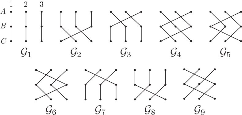
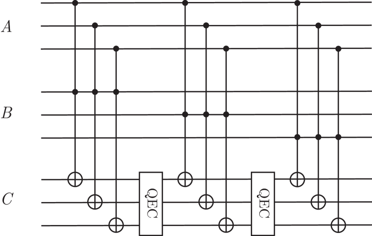
Although the physical implementation of the CCZ gate is not transversal, the physical gates may be reordered as they all commute with each other. In doing so, we can eliminate some but not all of the intermediate Rydberg population detection steps, to reduce the total number of measurement operations as we did for the fault-tolerant stabilizer measurements. Specifically, we group the three-qubit physical Rydberg gates of the protocol into nine groups of three, , so that each physical qubit is used in every group. One example of such a grouping is shown in Figure 3. With this reordering, detection for Rydberg leakage only needs to be performed after each group . This is because a Rydberg leakage error can only result in the blockading of the last two, the last, or no Rydberg gates within a group , and these cases correspond to disjoint possible sets of stabilizer eigenvalues for the three logical qubits (see Appendix F).
The Hadamard and CCZ gates together form a universal gate set for quantum computation Shi (2003), so we have demonstrated a scheme to construct any quantum operation on the code space fault-tolerantly against BBR errors.
IV.1.4 Logical state preparation
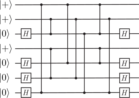
Finally, we show that we can prepare the logical state in a fault-tolerant manner. The most straightforward preparation of this state uses Steane’s Latin rectangle encoding method, whose circuit is shown in Figure 4 Steane (1996). In the Rydberg setup, we replace controlled-NOT gates by Rydberg controlled-phase gates with target qubit conjugated by Hadamard gates. Because the errors associated with Rydberg gates commute with controlled-phase operations, to leading order in , there will be at most one Pauli- error among the three data qubits initially in the state, and at most one Pauli- error among the four data qubits initially in the state. Although this could be a two-qubit error, it is correctable because the Steane code identifies and corrects and errors separately. In this procedure, we have assumed we detect for Rydberg population arising from BBR errors after each physical entangling gate and convert these errors to errors as necessary. In this way, by applying one round of stabilizer measurements and error correction, we will obtain (to leading order in ) a logical state with a Pauli error on at most one physical qubit.
IV.2 FTQC with BBR and RD errors
To address RD errors and intermediate state scattering, we must consider two new classes of leakage errors following the discussion of Section III: (1) leakage into the original Rydberg state and (2) leakage into the other hyperfine ground states, which we will also call “non-Rydberg leakage.” The first class of errors is similar to the quantum jumps in the BBR error model, and can be detected and corrected in the same way using an ancilla qubit. In the following sections, we will group this error together with BBR errors and refer to them as “Rydberg leakage” errors.
On the other hand, we demonstrate that leakage to other states in the hyperfine manifold can be converted into Pauli- type errors using optical pumping. For example, for 87Rb, we design the novel optical pumping protocol shown in Figure 5. One crucial property of this optical pumping procedure is that it does not affect the qubit coherence when there is no error. Furthermore, notice that while leakage in traditional QEC settings may be particularly difficult to address, requiring additional entangling gates or ancilla qubits, the particular multi-level structure of neutral atoms allows for efficient correction of these errors. Notably, this optical pumping can be performed without the need for qubit measurement and feed-forward corrections, allowing for efficient implementation in experiments.
The correction of non-Rydberg leakage errors can be incorporated into the fault-tolerant protocols of the previous section by performing this procedure between the Rydberg entangling gates. Thus, our protocols from the previous section will be fault-tolerant against generic intrinsic Rydberg decay errors. Furthermore, note that when considering this full error model including both BBR and RD events, it is no longer necessary to swap population between the state and the stretched ground state when addressing Rydberg leakage errors (i.e., one can omit Steps 1 and 3 in Appendix D); instead, the Rydberg population can be pumped directly to the state, converting it into a non-Rydberg leakage error which is corrected by optical pumping. The full protocols for fault-tolerant stabilizer measurement, the logical controlled-phase gate, and the logical CCZ gate are given in Algorithms 1-3.
-
1)
For each stabilizer :
-
a.
Initialize ancilla qubit to state.
-
b.
Apply gate to all data qubits .
-
c.
For each , apply the Rydberg gate . If , use ancilla qubit to detect for Rydberg population as described in Section IV.1; if a Rydberg leakage error is detected, convert it to a non-Rydberg leakage error . Finally, use the optical pumping technique of Section IV.2 to convert any possible non-Rydberg leakage error into a possible single-qubit error.
-
d.
Apply Hadamard gates to all data qubits .
-
e.
Measure in the basis.
-
f.
If measurement yields , break.
-
a.
-
2)
If any stabilizers are measured to be :
-
a.
Measure all stabilizers again, this time in the unprotected way and without checking for leakage. There was either already an error in the input, or an error occurred in the initial measurement process. The resulting outcomes will then be the correct stabilizer values to leading order in .
-
a.
-
1)
Apply single-qubit gates to all physical control and target qubits.
-
2)
For each :
-
a.
Apply the two-qubit Rydberg gate .
-
b.
Use ancilla qubit to detect for Rydberg population as described in Section IV.1.
-
c.
If a Rydberg leakage error is detected, convert it to a non-Rydberg leakage error .
-
a.
-
3)
Use the optical pumping technique of Section IV.2 to convert any possible non-Rydberg leakage error into a possible single-qubit error.
-
1)
Apply gate to all physical qubits .
-
2)
For each group of physical three-qubit Rydberg gates to apply (where are ordered as discussed in the main text or Figure 3):
-
a.
Apply gates in .
-
b.
Use ancilla qubit to detect for Rydberg population as discussed in Section IV.1. If Rydberg leakage is detected:
-
i)
Convert this leakage error to a possible single-qubit error.
-
ii)
Measure stabilizer eigenvalues and for each logical qubit in an unprotected way. This is safe because an error already occurred.
-
iii)
Apply the appropriate correction circuit for the correlated error (since the possible correlated errors all result in disjoint sets of possible syndromes; see Appendix F).
-
iv)
Measure stabilizers for all logical qubits in an unprotected way to detect for a possible single-qubit error induced by step i) above; correct this error if found.
-
v)
The remaining three-qubit Rydberg gates needed to implement the logical CCZ operation can all be applied in an unprotected way.
-
i)
-
c.
Use the optical pumping technique of Section IV.2 to convert any possible non-Rydberg leakage error into a possible single-qubit error.
-
a.
-
3)
Apply gate to all physical qubits .
While the above discussion has focused on intrinsic RD errors, the non-intrinsic errors of Section III.4 can also be incorporated into our FTQC protocols. Specifically, the errors resulting from Rydberg laser imperfections such as intensity and phase fluctuations only cause Pauli- errors and single-qubit Rydberg leakage errors, so they are already addressed within our current framework. Similarly, atom loss can be detected by using an ancilla qubit and performing a small leakage detection circuit; this is discussed in Appendix C. In this case, if a reservoir of atoms is available, we can also convert the atom loss error into a single-qubit Pauli- or error, for instance by replacing the lost atom with a new atom initialized to the state.
IV.3 Comparison to existing fault-tolerant quantum computing protocols
To demonstrate the significance of our Ryd-7 FTQC protocol and emphasize the importance of considering specific error models when designing QEC approaches, we now compare our model with existing general-purpose FTQC schemes proposed in Refs. Chao and Reichardt (2018a, b); Yoder et al. (2016). Specifically, we compare the costs of measuring stabilizers and implementing fault-tolerant logical operations, using as metrics the number of two- and three-qubit entangling operations required for the physical qubits, and the minimum number of ancilla qubits needed. Details on how these numbers can be obtained for the Ryd-7 protocol are provided in Appendix H.
Table 1 compares the minimum number of two-qubit gates and ancilla qubits required for fault-tolerant stabilizer measurement (and associated error correction) in various QEC proposals. The results for general-purpose FTQC protocols for the 7- and 15-qubit CSS/Hamming codes are based on the “flagged syndrome extraction” procedures presented in Refs. Chao and Reichardt (2018a); Yoder and Kim (2017); Chao and Reichardt (2018b). For each protocol, we separately present the resource cost for cases without any errors and the worst-case cost when an error is present (numbers in parentheses), as the former case is typically much more probable. While the number of ancilla qubits required is the same for all cases, we find that our protocol requires the smallest number of entangling operations in either case even though we must detect for leakage, an additional kind of error not considered in Refs. Chao and Reichardt (2018a); Yoder and Kim (2017); Chao and Reichardt (2018b).
Similarly, Table 2 demonstrates this comparison for the fault-tolerant logical CCZ gate, where our improvements are striking. The general-purpose implementation of this non-Clifford gate for three logical qubits in the -qubit Steane code is given by Yoder, Takagi, and Chuang Yoder et al. (2016); while this implementation requires only a modest number of physical two- and three-qubit gates, it requires a considerable overhead of additional ancilla qubits, making an experimental demonstration very challenging. On the other hand, while Chao and Reichardt’s proposal Chao and Reichardt (2018b) for a fault-tolerant Toffoli gate using the code significantly reduces the ancilla qubit count, the number of physical entangling operations is substantial. Our protocol uses only 2 ancilla qubits compared with 72 required in Yoder, Takagi, and Chuang Yoder et al. (2016), while using significantly fewer entangling operations (e.g. 60 two-qubit gates) than Chao and Reichardt Chao and Reichardt (2018b) (1416 two-qubit gates) even in the unlikely scenario where we must correct for an error. We note that while our protocol does use more three-qubit entangling gates than Ref. Yoder et al. (2016), such gates are nearly as straightforward to implement as two-qubit CZ gates in the Rydberg atom setup (see Section II).
These results clearly demonstrate the advantage of considering a hardware-specific error model and leveraging the unique capabilities of the Rydberg setup when designing FTQC schemes. In particular, even though we must correct for additional errors not considered in traditional settings, we can still dramatically reduce the required number of entangling gates or ancilla qubits.
IV.4 Scalable implementation
We now discuss some more details regarding the scalable implementation of our protocols, including potential geometrical layouts of physical qubits, resource trade-offs, and residual error rates.
Geometrical considerations. One particular advantage of the Rydberg atom platform is the flexibility in allowing arbitrary geometrical arrangements of atoms. Motivated by recent experimental demonstrations of near-deterministic loading and rearrangement of neutral atoms into regular lattice structures, we propose scalable FTQC architectures in which logical qubits form a coarser lattice on top of the lattice of physical atoms. For the Ryd-7 scheme, one natural layout in a two-dimensional atomic array setup could comprise placing physical atoms on the vertices of a triangular lattice (Figure 1a). In this geometry, the hexagonally shaped logical qubits (dark blue dotted hexagons) form a coarser triangular lattice, with ancilla qubits (A, pink) placed on the edges of this coarser lattice to mediate error correction and logical gates. Fault-tolerant universal quantum computation can be performed if nearest-neighbor logical qubits can be entangled; because physical entangling gates can only be implemented between atoms within a blockade radius , this defines a minimum required value of in terms of the closest atom-atom separation . Upon examining the physical gates required to implement the logical operations for the seven-qubit code, we find that the requirement in this case is (dotted grey line), an interaction range which has already been demonstrated in recent experiments Bernien et al. (2017). Details on the derivation of this minimal blockade radius can be found in Appendices I and J. This requirement on can be further reduced if atoms can be moved in between certain logical operations while preserving coherence between the hyperfine ground states Bluvstein et al. (2021a).
Resource tradeoffs. For any experiment, resource trade-offs may be made to minimize the total logical error probability. For instance, if the timescale of one round of measurements is much larger than typical gate times (as is the case in certain atomic setups), one may wish to reduce the number of measurement shots required at the expense of performing additional operations. This can be incorporated into our protocol by incoherently driving Rydberg states to the low-lying state after each entangling gate to convert any possible Rydberg leakage error into the non-Rydberg leakage . In this case, ancilla measurements are no longer necessary to detect and correct for Rydberg leakage errors, but this incoherent pumping would be done after every gate, regardless of whether an error had actually occurred. Alternatively, the number of entangling gates can be further reduced at the cost of additional measurements.
Improvements. The FTQC protocol presented in this section relies upon selection rules which impose restrictions on the possible RD error channels. Specifically, as mentioned in Section III, to leading order in the error probability, we ignored the decay channel arising from RD. Given the low branching ratio (determined numerically to be in 87Rb, see Appendix A) from the stretched Rydberg state to , this is already a reasonable assumption; however, several approaches can be taken to suppress the probability of such errors even further. First, this probability can be reduced by a factor of roughly 3 or 4 by employing a “shelving” procedure in which population in the state is swapped with the stretched ground state before and after each entangling gate, due to the lower branching ratio from to this stretched state. To avoid errors arising from near-degenerate Rydberg transitions in this case, one would also transfer population in the state to to perform Rydberg excitation in this case, instead of exciting out of the manifold. Moreover, by utilizing higher magnetic fields to reduce the branching ratio for RD processes involving large , or by using a species with higher nuclear spin (e.g. 85Rb) where the shelving state can be further separated from the stretched Rydberg state, one can suppress the probability of such errors to even higher orders.
V Leading-Order Fault-Tolerance with a Repetition Code
Given that all Rydberg errors can be converted to the -type, one may naturally ask whether the full seven-qubit Steane code is even necessary to detect and correct these errors; in particular, one may be tempted to simply use a three-qubit repetition code in the basis to detect and correct -type errors. In such a code, the logical states are
| (12) |
and stabilizer operators are
| (13) |
However, direct application of such a repetition code for FTQC is challenging even with this biased noise model, as one must be able to implement every physical gate in the encoding, decoding, stabilizer measurement, and logical gate procedures without introducing Pauli- or -type errors at any stage—that is, each gate must be implemented in a bias-preserving way. This requirement can easily be satisfied for certain physical gates such as the Rydberg controlled-phase or collective gates (after all leakage errors are mapped to Pauli- type), but is much more difficult to fulfill for other gates. Specifically, measurement of the stabilizers of Eq. (13) requires performing controlled-NOT (CNOT) gates as shown in orange in Figure 1e.
While a standard implementation of the CNOT gate in a Rydberg setup would comprise the Rydberg controlled-phase gate conjugated by single-qubit Hadamard gates on the target qubit, this would not be bias-preserving: for example, a error on a target qubit during a controlled-phase gate would become an error once the final Hadamard gate is applied (Figure 6). In other setups, where a -rotation of the target qubit about the axis on the Bloch sphere can be performed conditioned on the state of the control qubit (e.g. by engineering a interaction), an over-rotation or under-rotation error would also translate to an error and violate the bias-preserving constraint.
Indeed, the implementation of a bias-preserving CNOT may seem unfeasible at first, in light of a no-go theorem proven in Ref. Guillaud and Mirrahimi (2019): a bias-preserving CNOT gate is not possible between two qubits encoded in systems where the underlying Hilbert space is finite-dimensional, because the identity gate cannot be smoothly connected to CNOT while staying within the manifold of bias-preserving operations. One way to circumvent this no-go theorem was recently developed for circuit QED systems in Refs. Guillaud and Mirrahimi (2019); Puri et al. (2019), where the qubits can be encoded in the continuous phase space of the photon field, and the dominant source of error—photon loss—can be manipulated via parametric driving schemes to cause only -type errors. In our setup, we circumvent the no-go theorem using the special fact that certain pulses in our finite-dimensional atomic system—the pulses between hyperfine states—can be implemented at very high fidelities, so that our leading-order errors arise only from Rydberg pulse imperfections and Rydberg state decay. This allows us to develop a novel laser pulse sequence for entangling Rydberg atoms that directly implements a CNOT or Toffoli gate while preserving the noise bias. Our protocol can be applied on any atomic species with sufficiently high nuclear spin (). For concreteness, we will illustrate the protocol using the example case of 85Rb throughout the section.
V.1 Bias-preserving CNOT in a Rydberg atom setup
As shown in Figure 6, the standard implementation of a CNOT gate in a Rydberg system is not bias-preserving. In particular, given the error model for Rydberg gates, errors on the target qubit can be induced in two ways. First, the target qubit could directly undergo a Rydberg error (e.g. radiative decay) during the controlled-phase gate, resulting in a Pauli- error that is transformed into an error after the Hadamard gate (purple in Figure 6). Alternatively, the control atom could decay from the Rydberg state to the ground state at some point during the controlled-phase gate, so that the target qubit Rydberg pulses, which should have been blockaded, are now resonant during the controlled-phase gate. This results in a two-qubit correlated error between the control and target atoms, where the target atom undergoes an -type error.
Here, we begin by introducing a novel entangling gate pulse sequence for Rydberg atoms to address the target atom errors. In this discussion, we first assume that the Rydberg pulses on the target atom are either all resonant or all blockaded; that is, we ignore the possibility of a neighboring Rydberg atom decaying during the target atom sequence. We then include this effect and also eliminate the correlated errors by introducing an ancilla qubit and making use of two Rydberg states with different blockade radii.
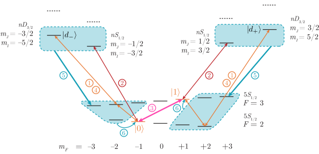
To remove the target atom errors, we wish to design an entangling gate protocol which uses Rydberg states to conditionally swap and population directly, without the change-of-basis from Hadamard gates. This can be accomplished for atomic species with high enough nuclear spin (). We consider qubits encoded in the 85Rb clock states , (orange levels in Figure 7), which have a magnetic field-insensitive transition frequency at low fields. The protocol then proceeds as illustrated in Figure 7.
The first step of the procedure aims to transfer population in the qubit state (respectively, to the Rydberg state (respectively, ) conditionally, dependent on the state of a control atom. This is achieved because the Rydberg pulses from the qubit states to are resonant if and only if there are no neighboring atoms in or nearby Rydberg states. Since each stretched Rydberg state predominantly decays only into ground states with during RD processes, the and populations will not be mixed by Rydberg state decay; however, due to the possible decay channels and , it is possible that the first step fails to excite the atom into a Rydberg state even in the absence of nearby Rydberg population. Consequently, in the second step, we again attempt to transfer the qubit states to Rydberg states, this time using resonant pulses and . Then, in the third step, the population in the qubit states is swapped via the pulse . We note that this only swaps population if nearby Rydberg atoms prevented transfer out of the qubit manifold in Steps 1 and 2. Step 4 then acts to invert the first step.
After Step 4, we find that if no Rydberg errors have occurred, the atomic state is restored to the original qubit state (identity map) when no nearby Rydberg population is present, or to the opposite qubit state otherwise. Rydberg errors can occur only if the pulses of Step 1 are resonant (i.e. if no nearby Rydberg atoms are present); moreover, because transitions from (respectively, ) only result in states with (), any Pauli errors must be of -type (for example, projectors , ), and any leakage error must be of the form or . One can then verify that after the pumping steps (5 and 6), the resulting state is the same as in the error-free case, up to a local error of type (e.g. , ). As before, the error channels for intermediate state scattering and other Rydberg pulse imperfections can be captured by our error model which contains BBR and RD errors.
| Rydberg Transitions Addressed | |||||
| Step | Atom | Atom | Atom | ||
| (a), (c) | none |
|
|||
| (b) |
|
||||
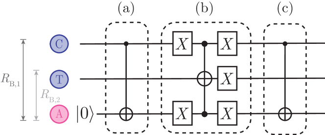
Having eliminated errors arising from target qubit Rydberg errors, we now proceed to address the second type of potential error arising from control qubit decay. The crux here is to utilize multiple Rydberg atoms (e.g. a control atom and an ancilla atom) to blockade the target atom if the control is in the state; in this way, if one of the atoms decays, the remaining Rydberg atom(s) can still ensure (to leading order in the total error probability) that the Rydberg pulses on the target atom do not become resonant. For the simplest case, the bias-preserving CNOT gate can be implemented with one ancilla qubit. Let us assume that the control (), target (), and ancilla () atoms are placed evenly along a line, with the target atom in between the control and ancilla atoms; the ancilla atom is initialized in the state . We can make use of two sets of Rydberg states, and , with blockade radii and , respectively, such that and , where is the distance between neighboring atoms (i.e. between and or and ); as such, atoms and are within the blockade radius , but beyond , whereas neighboring atoms are within the blockade radius . The full bias-preserving CNOT gate between the control and target atoms then consists of the three-step procedure illustrated in Figure 8, followed by correction of Rydberg leakage errors (as discussed in Appendix D) and optical pumping to eliminate non-Rydberg leakage errors (Figure 5). The Rydberg transitions addressed in each step of Figure 8 are listed in Table 3.
This protocol is robust against control atom decay errors, as the Rydberg pulses on atom are resonant only if neither nor is excited to the Rydberg state, and one can see that, to leading order in the total error probability, this can only occur if starts in the state: first, if begins in the state, must also remain in , so the state of will not be flipped. On the other hand, if begins in the state and no decay events occur during Step (a), after this step. The Rydberg pulses for are blockaded in Step (b), so its state will be flipped. Finally, if begins in the state but decays during the first step, or after this step. The Rydberg pulses for are still blockaded in Step (b), so its state will be flipped. Finally, Rydberg decay errors in Step (c) will result in projections of the form or , which can be expressed in terms of errors. In this way, we have eliminated any possible source of errors arising from the CNOT gate, to leading order in the total error probability. The protocol can also be generalized to implement a bias-preserving Toffoli gate (see Appendix G and Figure 14). Potential improvements leading to suppression at higher orders are discussed in Section V.3.
The ability to couple atoms to two sets of Rydberg states and in our bias-preserving CNOT implementation allows atom to interact with atom during Steps (a) and (c) of Figure 8, but not during Step (b). Alternatively, this tunability of interaction could be achieved with only a single set of addressable Rydberg states if the atoms can be rearranged while preserving coherence between hyperfine ground states Bluvstein et al. (2021a). In this case, one could move atoms in between Steps (a) and (b) to further separate , , and from each other such that the distance between and becomes greater than , while the distance between either of them and atom remains less than . The atoms can then be returned to their original configuration after Step (b) to allow for interaction between and during Step (c).
V.2 Leading-order fault-tolerance with the repetition code
The bias-preserving operations discussed above allow for a direct implementation of each component of the three-atom repetition code to perform quantum computation with leading-order fault-tolerance on a Rydberg setup. In particular, logical states (12) can be prepared or measured fault-tolerantly in the basis by transversally preparing or measuring each atom. The measurement of stabilizers (13) can be achieved using the circuit of Figure 1e, where each controlled-NOT gate is done in the bias-preserving way described above; for robustness against errors occurring during this circuit, one must repeat the stabilizer measurement if either or is measured to be .
A universal set of logical operations can be achieved by implementing a logical Toffoli gate and a logical Hadamard gate as in the seven-qubit case, using the bias-preserving pulse sequences presented above. While not strictly necessary, we will also discuss the implementation of logical controlled-phase and CCZ gates. These may be of use for simplifying the implementation of certain quantum algorithms, as they do not require the new bias-preserving pulse sequences and can be implemented using the standard method for performing Rydberg-mediated entangling gates as described in Figure 2.
Logical Toffoli gate. One important feature of the encoding (12) is that the logical (respectively, ) state consists of an equal superposition of states with an even (odd) number of physical qubits in the state:
| (14) |
From this observation, one can see that the Toffoli gate with logical control qubits , and logical target qubit can be implemented as a product of nine physical Toffoli gates:
| (15) |
Each physical Toffoli gate can be implemented in a bias-preserving fashion as described previously, resulting in at most one physical error in each logical qubit, assuming that Rydberg and non-Rydberg leakage errors are converted to possible errors after each physical gate. In this case, however, while errors on the control qubits or would commute with remaining Toffoli gates, a error on one of the physical qubits of could spread to multiple errors within or after subsequent Toffoli gates if uncorrected. To address this, we order the physical gates as shown in Figure 9 and perform error correction after every three physical Toffoli operations by measuring the stabilizers (13); this follows the pieceable fault-tolerant implementations of non-transversal gates discussed in Refs. Yoder et al. (2016); Guillaud and Mirrahimi (2019). In this way, after the entire logical gate, there will be at most one physical qubit error per involved logical qubit.
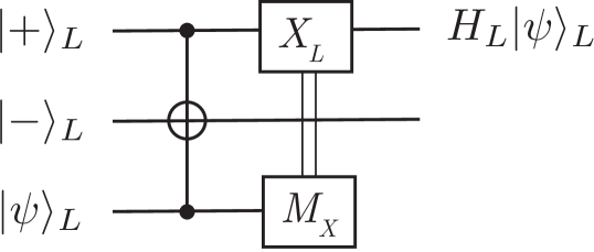
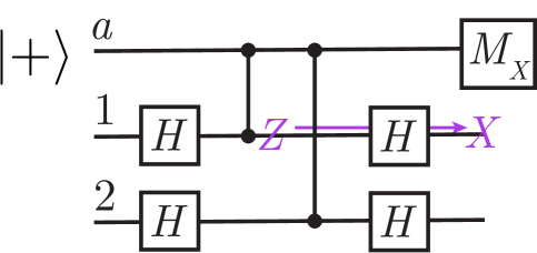
Logical Hadamard gate. Unlike the Steane code, the repetition code is not a CSS code, and its logical Hadamard gate is not transversal. However, as discussed in Ref. Guillaud and Mirrahimi (2019), the logical Hadamard gate can be implemented using a logical Toffoli gate combined with fault-tolerant measurements in the basis, as shown in Figure 10. The logical Hadamard gate combined with the logical Toffoli or CCZ gate form a universal set of logical operations.
Logical controlled-phase gate. A logical controlled-phase operation in the three-qubit code can be implemented using the standard Rydberg pulse sequences for controlled-phase gates between each pair of physical qubits, where and belong to the encoding of logical qubits and , respectively:
| (16) |
To correct for the errors that occur during gates, one should remove any Rydberg population and apply the optical pumping scheme to convert non-Rydberg leakage errors into possible errors after each physical controlled-phase operation. The stabilizers only need to be measured after the entire logical operation, since Rydberg gates can only produce errors which commute with all the physical CZ gates being performed (and hence do not spread to higher-weight errors).
Logical CCZ gate. Similarly, a logical controlled-controlled- operation between logical qubits , , ,
| (17) |
can be implemented as a sequence of physical CCZ operations:
| (18) |
As with the case of logical CZ, Rydberg and non-Rydberg leakage errors should be converted to possible errors after each physical gate. Notice that even though the logical CCZ is not transversal, this implementation is leading-order fault-tolerant because any given physical gate can result in at most one physical qubit error per logical qubit; since errors commute with the remaining gates applied, they do not propagate to become multi-qubit errors. While the CCZ gate is not strictly needed for the universal gate set given a leading-order fault-tolerant implementation of the logical Toffoli gate, it requires fewer resources to implement than the logical Toffoli as it uses the standard, simpler Rydberg gates instead of the more complicated bias-preserving CNOT pulse sequences (see Table 2). Thus, this operation may be useful for reducing the resource cost of certain quantum algorithms.
V.3 Scalable implementation
We now discuss some important considerations for the scalable implementation of our Ryd-3 protocol, including the geometrical layout, resource requirements, and potential improvements.
Geometrical layout. Based on the implementations of logical gates, stabilizer measurement, and the underlying bias-preserving CNOT given in the previous sections, we find that a convenient geometry is to place data and ancilla atoms on the vertices of a triangular lattice as shown in Figure 1d, with three data atoms comprising a logical qubit. In this configuration, the logical qubits form a coarser triangular lattice, as in the case of Ryd-7. As discussed in Section V.1, two Rydberg states with different blockade radii are required to implement the bias-preserving CNOT gate. Based on the interaction ranges required for performing fault-tolerant stabilizer measurements and logical operations as described previously, we find that the larger blockade radius must be greater than (dark grey in Figure 1d), where is the nearest-neighbor spacing on the square lattice; this is required for some of the physical gates in the logical CCZ and Toffoli gates. On the other hand, the smaller blockade radius should be strictly between and for efficient implementation of the bias-preserving CNOT and fault-tolerant stabilizer measurements (light grey in Figure 1d). Details on how to obtain the requirement can be found in Appendix I.
Alternatively, the data and ancilla atoms can be placed on the vertices of a square lattice in an alternating fashion (see Appendix K). In this case, the blockade radius requirements are and . For both the triangular lattice and square lattice geometries, experimental developments allowing for rearrangement of atoms while preserving the coherence of hyperfine ground states could be used to further reduce the requirement on and eliminate the need for a second set of Rydberg states with blockade radius .
Resource comparison. We now compare the resource cost of our Ryd-3 protocol with our Ryd-7 approach and the traditional general-purpose proposals of Refs. Yoder et al. (2016); Chao and Reichardt (2018b). Compared to the seven-qubit approaches, we find that the number of entangling gates required for extraction of all stabilizers for error correction is significantly reduced due to the smaller number of data atoms and stabilizers per logical qubit, without a substantial increase in the number of required ancillas (Table 1). On the other hand, while the cost of performing a logical CCZ gate is essentially the same as in Ryd-7, the number of gates required for a logical Hadamard is larger (Table 2) because the Hadamard gate is not transversal using the repetition code. Notice that each CNOT gate in a stabilizer measurement translates to two two-atom entangling gates and one three-atom entangling gate in the bias-preserving implementation; this is reflected in Tables 1 and 2 (more details on obtaining the Ryd-3 resource costs can be found in Appendix H). Nevertheless, the number of required gates is still very modest compared to logical operations in other universal FTQC gate sets. As a result, we believe that the substantial resource cost reduction for stabilizer measurements and the improved efficiency in using fewer atoms make the three-atom approach very promising for near-term implementation.
Improvements. While our bias-preserving CNOT suppresses -type errors to leading order, the amount of bias preservation is ultimately limited by the decay rate of the stretched Rydberg state into the qubit states. To further suppress these errors, one can shelve to stretched Rydberg states with higher angular momentum, which would have lower decay rate to the qubit states. Alternatively, one can also use an atomic species with higher nuclear spin, where the qubit states can be separated from the stretched Rydberg state by a larger amount . Likewise, one could also increase the magnetic field in the experimental setup to suppress the rate of transitions with high . To achieve suppression beyond the leading order, one can then use more Rydberg “shelving” states in the target atom pulse sequence of Figure 7 and more ancillas to suppress the effects of control atom decay.
The Ryd-3 hardware-tailored FTQC approach inherently addresses errors due to Rydberg pulse imperfections in addition to those arising from the finite Rydberg state lifetime, as these errors fall within a subset of the radiative decay errors. As in the Ryd-7 case, the Ryd-3 approach can also be enhanced to further protect against atom loss errors at the expense of additional physical operations by incorporating the atom loss detection scheme described in Appendix C in between Rydberg operations.
VI Further Considerations Towards Experimental Implementation
In this section, we discuss further considerations on how our FTQC protocols can be implemented in near-term experiments. Recent experiments using neutral alkali atom systems have already achieved near-deterministic trapping, loading, and rearrangement of tens to hundreds of atoms into two-dimensional lattice structures such as the triangular lattice needed for our protocol Bluvstein et al. (2021b); Ebadi et al. (2020); Barredo et al. (2016); Kim et al. (2018). Furthermore, high-fidelity manipulations within the ground state manifold and two- and three-atom Rydberg blockade-mediated entangling gates have been demonstrated Levine et al. (2018, 2019); Graham et al. (2019). Blockade interactions between Rydberg atoms separated by three times the lattice spacing, which is the interaction range required for both of our protocols, have also been realized Bernien et al. (2017).
VI.1 Measurements and feed-forward corrections
To perform QEC, an important ingredient is the ability to measure the states of ancilla qubits and/or detect Rydberg population and perform feed-forward corrections. Several approaches can be considered. One promising way to rapidly measure individual qubit states is to resonantly drive a cycling transition and detect the scattered photons Bergschneider et al. (2018). At lattice spacings of a few microns, this detection scheme could be limited by atom heating and cross-talk from the reabsorption of scattered photons by neighboring atoms Steck (2019). To this end, recent developments in coherent transport of entangled atom arrays Bluvstein et al. (2021a) can be used to mitigate these effects by moving the selected ancillary atom(s) into a detection zone far away from the rest of the array before it is measured.
To estimate the maximum speeds of coherent transport before atom loss and heating become significant, one can consider the harmonic oscillator potential (i.e. the optical tweezer) that the atom is trapped in. Following the analysis in Refs. Carruthers and Nieto (1965); Bluvstein et al. (2021a), the average energy increase to the atom will be , where is the particle mass and is the Fourier transform of the acceleration profile evaluated at the trap frequency . When is linear in time, this energy depends on the total displacement and the time of movement as approximately Based on this estimate, it is reasonable to achieve substantial atom displacements m within s for performing feed-forward applications: for typical trap frequencies , the atom’s vibrational quantum number would increase by only . Indeed, such transport has been demonstrated by Ref. Bluvstein et al. (2021a) without significant decoherence or atom loss due to heating. Moving the atoms by a distance would then suppress reabsorption rates during ancilla readout to , where is the absorption cross-section Steck (2019). Moreover, detuning the optical transitions for ancilla atoms by further suppresses reabsorption by a factor , where is the resonance linewidth, and can be readily achieved with moderate powers of a light-shifting beam Steck (2019). Between moving and light-shifting the ancillary atoms, cross-talk errors on the data qubits can be suppressed by five or more orders of magnitude, to negligible levels.
Alternatively, the measurement of ancilla qubit states can be achieved by using two different atomic species for the data and ancilla atoms (such as two different isotopes of the same atom or two different atomic species). In this approach Zeng et al. (2017); Singh et al. (2021), the ancilla atoms can still interact with the data atoms when both are coupled to Rydberg states, while they can be measured independently without disturbing the data atom states.
Finally, fast detection schemes were recently demonstrated in experiments with small atomic ensembles using Rydberg electromagnetically induced transparency (EIT) Xu et al. (2021). These could be potentially utilized to identify Rydberg population after entangling gates. These schemes could be incorporated into the tweezer array platforms by creating larger, elongated traps at selected locations containing optically dense atomic ensembles. In this approach, the Rydberg blockade effect leads to a sharp signature in the absorption spectrum of a weak EIT probe beam depending on whether a nearby Rydberg atom is present. Due to the collectively enhanced Rabi frequency, the detection time can be reduced to Xu et al. (2021), comparable to the duration of an entangling gate. This ultrafast, non-destructive Rydberg atom detector thus provides a promising implementation for the measurement and feed-forward corrections needed for our protocols.
VI.2 Implementation with alkaline earth(-like) atoms
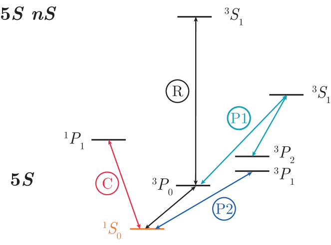
In this work, we have focused primarily on developing FTQC protocols for neutral alkali atoms coupled to Rydberg states. Recently, significant progress has also been made towards using alkaline earth(-like) atoms such as Sr and Yb for Rydberg-based quantum computations Madjarov et al. (2020); Wilson et al. (2019). In this section, we show how our methods can also be applied for such setups. While we focus on an example of 87Sr for concreteness, our discussion is generic for fermionic species of alkaline earth(-like) atoms.
For alkaline earth(-like) atoms, the ground states have no electronic orbital or spin angular momentum, so the only source of degeneracy is the nonzero nuclear spin (which can be quite large, e.g. for 87Sr). For our protocols, a most convenient qubit encoding uses the stretched ground states: , . In this encoding, strong cooling and state readout can be implemented via the transition, while narrow-line cooling can be performed on the transition. Entangling gates can be implemented by selectively exciting the state to a stretched Rydberg state. This state selectivity can be achieved by coherently mapping one of the qubit states to the clock state, performing Rydberg pulses between the clock state and the Rydberg state, and mapping back to the ground state, where we have utilized the linear Zeeman shift in the clock transition arising from hyperfine coupling between the and states Boyd et al. (2007). The relevant level diagram is shown in Figure 11 for the case of 87Sr (see also Ref. Ludlow et al. (2015)).
During these entangling operations, an atom in the Rydberg state may undergo various errors such as BBR transitions, RD, or intermediate state scattering as described in Section III. For alkaline earth(-like) atoms, the resulting Kraus operators can be described by Pauli- errors and quantum jumps to Rydberg states, ground states, or metastable states as allowed by dipole selection.
Following our approach for alkali atoms, we must convert all such errors to Pauli- errors to apply our FTQC protocols. By using ancilla atoms and the blockade effect, the quantum jumps to Rydberg states can be corrected in the same fashion as for alkali atoms. However, due to the presence of metastable levels, the correction of non-Rydberg leakage errors is more complicated, and the optical pumping must be done in two stages (see Figure 11): (1) Use -polarized light from the states to the triplet excited state to re-pump all states to the manifold; these states will decay back into the ground states. (2) Use -polarized on the narrow-line cooling transition to pump ground states with to the stretched ground state . After these two steps, all non-Rydberg leakage errors will be mapped to the error , which is expressible in terms of Pauli- errors. We note that while Pauli- errors could in principle arise from polarization impurities in the beam in the second stage, this would require several consecutive polarization imperfections, each of which has a very low probability of roughly ; thus, the overall probability of Pauli- errors arising from imperfect polarization is negligible. Therefore, by using this optical pumping scheme to convert all non-Rydberg leakage errors to errors, the FTQC schemes of Sections IV and V can be implemented in alkaline earth(-like) atoms.
VII Conclusions and Outlook
In this work, we have presented a detailed analysis of the dominant error channels arising in quantum computation using neutral Rydberg atoms. We show that although the multilevel nature of atoms and the complex decay channels for Rydberg states lead to many additional types of errors not considered in traditional QEC settings, the specific structure of the error model allows us to design hardware-efficient FTQC protocols based on the seven-qubit and hardware-tailored three-qubit codes with significantly reduced overhead compared to general-purpose schemes. The crux of these results is the ability to convert the complicated error model to Pauli- errors by introducing ancilla atoms and making use of the Rydberg blockade effect, dipole selection rules, and new schemes for optical pumping. To use the three-atom repetition code, we designed a new laser pulse sequence to implement bias-preserving CNOT and Toffoli gates. For both protocols, we propose simple, scalable geometrical layouts and demonstrate feasibility of all components of FTQC for near-term implementation.
Our results provide an important step towards building large-scale quantum computers based on neutral atom setups and highlight the importance of designing FTQC schemes based on the specific structure of the error model and the unique capabilities of the hardware platform. Compared to some general-purpose FTQC protocols, our hardware-efficient approaches for Rydberg systems enable an order-of-magnitude improvement in resource overhead in terms of the number of physical gates or required ancillas. We believe many of the ideas developed in this work, such as the exploitation of the multi-level structure of the physical system, are transferable to other quantum computing platforms such as trapped ions and superconducting qubits. In the former case, an optical pumping-based protocol to mitigate leakage in ions with low nuclear spin such as 171Yb+ was recently developed and realized experimentally Hayes et al. (2020); we believe that insights from our work would be helpful for developing more general leakage correction methods in such setups and incorporating them into FTQC protocols.
Several interesting extensions can be considered. For example, while we have primarily quantified the resource cost for FTQC proposals by studying the number of qubits and gates required, another related and commonly used metric is the error threshold, which amounts to the physical qubit and gate fidelities required to produce logical error rates that are lower than the physical error rate. One may estimate the error thresholds for two- and three-qubit gates directly by using the numbers presented in Tables 1 and 2 and requiring each logical operation or stabilizer measurement step to have at most a single error, but it can be more useful to obtain the precise numbers for these thresholds via numerical simulation.
A more detailed study of the error threshold would be especially helpful if one intends to extend our work to codes with distance greater than and compare the relative performance and scalability of these approaches with our current proposal. One particularly intriguing direction could be to evaluate the performance and resource cost of existing FTQC protocols based on topological codes such as surface codes or color codes Bravyi and Kitaev (1998); Fowler et al. (2012); Bombin and Martin-Delgado (2006, 2007); Terhal (2015); Auger et al. (2017) upon applying our techniques to address Rydberg and non-Rydberg leakage errors. Indeed, one recent work has already demonstrated ultrahigh error threshold in the surface code when the underlying noise model is biased Tuckett et al. (2018); this motivates the use of surface codes in a Rydberg system where dominant errors have all been converted to Pauli- type. For near-term implementations, more detailed studies considering a combination of current experimental capabilities and specific technical imperfections together with the intrinsic Rydberg state decay errors may also allow for improved error rates in encoded qubits and operations. Finally, after eliminating all of the Rydberg-specific leakage errors using our FTQC protocols, one could concatenate our codes with more traditional QEC approaches to address any higher-order Pauli- or -type errors that were neglected in our studies, or to further suppress the logical error rate to even higher orders.
Note added: In the process of revising and preparing this second version of our manuscript, we became aware of the related work of Ref. Wu et al. (2022), which proposes an efficient approach to FTQC in alkaline earth atoms based on converting Rydberg leakage into erasure errors by detecting the exact location of the leakage and replacing atoms lost during the detection process.
Acknowledgments: We thank Maya Miklos, Soonwon Choi, Florentin Reiter, Hannes Pichler, and Hyeongrak Choi for helpful discussions. Special thanks go to Ofer Firstenberg and Leo Zhou for providing code which we used to calculate dipole matrix elements for the blackbody radiation and radiative decay transitions in 87Rb. This work was supported by the Center for Ultracold Atoms, the National Science Foundation, the U.S. Department of Energy (DE-SC0021013 & LBNL QSA Center), ARO MURI, the DARPA ONISQ program, QuEra Computing, and Amazon Web Services . I.C. acknowledges support from the Alfred Spector and Rhonda Kost Fellowship of the Hertz Foundation and the Paul and Daisy Soros Fellowship. I.C. and H.L. acknowledge support from the Department of Defense through the National Defense Science and Engineering Graduate Fellowship Program. D.B. acknowledges support from the NSF Graduate Research Fellowship Program (grant DGE1745303) and the Susan and Richard Miles Fellowship of the Hertz Foundation.
Appendix A Numerical Computation of Branching Ratios and Transition Rates
In this section, we present the results of numerical computation of branching ratios for BBR and RD transitions out of the stretched Rydberg state , , for 87Rb.
A.1 Blackbody radiation-induced transitions
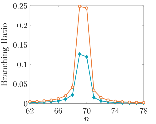
To quantify the relative probability of transitioning into different nearby Rydberg states, we compute the rate of BBR transitions from a given Rydberg state to other Rydberg states using the Planck distribution of photons at the given temperature and the Einstein coefficient for the corresponding transition:
| (19) |
where is the transition frequency ( and are energies of the initial and final states) and
| (20) |
In the above equations, , , and is the radial matrix element for the electric dipole transition .
For this work, we used analytic formulas from Refs. Kaulakys (1995) and Kamta et al. (1998) to numerically compute the radial dipole matrix elements for single-photon BBR transitions from the stretched Rydberg state , , of 87Rb. We then computed the corresponding transition rates using Eq. (19), and normalized these by the total BBR rate (see Eq. (3)) to obtain the branching ratios. The branching ratios for states with and are plotted in Figure 12 as empty orange circles and filled blue diamonds, respectively. Indeed, we find that the atom decays primarily to the and states as illustrated in Figure 1c.
A.2 Radiative decay
As shown in Figure 1c of the main text, the radiative decay transitions from the stretched , , Rydberg state of 87Rb are almost entirely two- or four-photon decay processes to one of the five states in the ground state manifold; this fact was important for converting all Rydberg errors to type for fault-tolerant quantum computation. To justify this, we numerically computed the branching ratios for multi-photon spontaneous emission processes by evaluating the ratios of individual transition rates for each decay channel, which are given by the Einstein coefficients of Eq. (20). Due to the cubic dependence of these coefficients on transition frequency, the primary contributions arise from dipole-allowed transitions to states near the ground state manifold. The dipole matrix elements for such transitions scale with the effective principal quantum number of the Rydberg state as . The total RD rate is then given by a sum over Einstein coefficients for all possible target states:
| (21) |
By computing the radial dipole matrix elements using analytic formulas from Refs. Kaulakys (1995) and Kamta et al. (1998), we evaluated the branching ratios for RD processes out of the , , stretched Rydberg state for 87Rb.
| Branching ratio | ||
| 2 | 2 | 0.534 |
| 2 | 1 | 0.177 |
| 2 | 0 | 0.055 |
| 2 | 0.003 | |
| 2 | 0.001 | |
| 1 | 1 | 0.168 |
| 1 | 0 | 0.059 |
| 1 | 0.003 |
The results of this computation are shown in Table 4. Indeed, we find that the branching ratios for the remaining three states are each on the order of , significantly smaller than those for the dominant five transitions. If the total error probability is already very small, these three processes (in particular, the decay to the stretched state with minimal ) are highly unlikely.
Appendix B An Example of Master Equation Solution for Radiative Decay
In Section III.2, we argued that the Kraus operators corresponding to spontaneous emission events from the Rydberg state to the qubit are
| (22) |
where , , and the proportionality constants depend on the specific Rydberg pulse being performed and the probability for an atom in the Rydberg state to decay to the state. We now proceed to derive these constants for the special case of a pulse on the Rydberg transition by analytically solving the quantum master equation. For this example calculation, we will ignore BBR transitions and RD transitions to other hyperfine states; these can be included as a straightforward extension.
The master equation for this driven three-level system is (setting )
| (23) |
where denotes the density matrix of the system, is the driving Hamiltonian, is the quantum jump operator corresponding to spontaneous emission , and is the probability for an atom in the Rydberg state to decay to . We assume the qubit is initially encoded in the hyperfine manifold , so that the initial density matrix can be written as
| (24) |
(we order the matrix columns and rows as ). Upon solving the resulting coupled first-order differential equations, we find that the final state after the pulse with decay is, to leading order in ,
| (25) |
Here, is the duration of a pulse. Indeed, Eq. (25) confirms our intuition from Section III.2 that the coherences , vanish upon “averaging” over all possible transition times during the pulse.
One can then verify that, to leading order in , the Kraus operators
| (26) | ||||
| (27) |
| (28) |
| (29) |
give rise to the desired evolution from to provided we take and .
Appendix C Atom Loss Errors
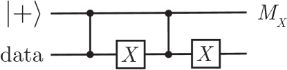
As mentioned in Section III.4 of the main text, neutral atom setups can also suffer from atom loss errors if the trapping is imperfect, or if the trapping lasers need to be turned off during Rydberg excitation (e.g. as done for 87Rb in Ref. Bernien et al. (2017)). Fortunately, such errors can also be detected and corrected within our FTQC framework at the cost of one ancilla qubit and some extra gates for each operation. In particular, an atom loss event can be detected by applying the circuit of Figure 13 for each data qubit after using the optical pumping technique to correct for leakage out of the computational subspace. The ancilla measurement will then produce in the presence of atom loss, and if such an error did not occur. Once detected, an atom loss error can be converted to a single-qubit Pauli- or type error if a reservoir of atoms is available, for instance by replacing the lost atom with a new atom initialized to the state.
We now discuss the steps needed for establishing robustness against errors occurring during this circuit. As in the case of fault-tolerant Rydberg leakage detection discussed in Appendix D, to protect against ancilla errors in Figure 13, we again adopt a multi-step ancilla measurement protocol and require two positive ancilla measurements to confirm an atom loss error. On the other hand, any phase-flip error on the data qubit cannot propagate to more than a single physical qubit error per logical qubit in the universal gate set implementations for Ryd-7 or Ryd-3. Leakage errors (Rydberg or non-Rydberg) can be addressed by repeating the respective re-pumping procedures after applying the atom loss detection circuit. Thus, by incorporating this circuit into the implementation of fault-tolerant stabilizer measurements and logical operations in Sections IV and V, we can also address atom loss errors in our FTQC protocols.
Notice that this circuit can be used for atom loss after correcting for leakage into atomic states outside the computational subspace by using the blockade effect and optical pumping techniques. In addition, this approach does not distinguish between atom loss and leakage into other hyperfine states, so it can also be used to suppress any residual hyperfine leakage errors.
Appendix D Converting Rydberg Leakage to Pauli Errors
Once a Rydberg leakage error is detected, it can be converted to an atom loss error by ejecting the Rydberg atom, which is naturally done by the anti-trapping potential from the tweezer Bluvstein et al. (2021a) and can be expedited by pulsing a weak, ionizing electric field Beguin (2013); Cohen (2003); Wu et al. (2022). The exact location of the ejected atom can be determined by following the atom loss protocol outlined in Appendix C and Figure 13 444In this case, the atom loss protocol does not need to be applied in a robust fashion, since an error has already occurred.; subsequently, the ejected atom can be replaced with a fresh atom prepared in the state. Although this process simply replaces the Rydberg atom by an atom in the state, by using the operator identity , it is straightforward to see that the resulting state is now a superposition of the original state without error, and the same state with a error on this physical qubit. Such -type errors can be detected and corrected for using stabilizer measurements in both the seven-qubit and three-qubit codes. This procedure can also be modified to convert the Rydberg leakage error to a Pauli -type error by applying Hadamard gates at the beginning and end; this is used to in the logical CCZ gate for Ryd-7 (see Algorithm 3).
To reduce the need for applying the atom loss correction circuit, one could add a preventative step after every entangling gate which incoherently re-pumps any remnant population in several most probable Rydberg states into the qubit state. This re-pumping can be implemented via the following three-step procedure:
-
1.
Swap the population in and the stretched ground state .
-
2.
For the most probable final states of a BBR transition (or the Rydberg state in the case of RD), perform a Rydberg laser pulse that sends (or ) to a short-lived state. In particular, we choose the state with the smallest possible , largest possible , and largest possible . This state will quickly decay to the stretched state , and cannot decay to any other ground state.
-
3.
Repeat Step (1).
By applying this procedure preventatively, one can convert a large fraction of Rydberg leakage errors to -type errors without the need for the atom loss correction circuit of Figure 13.
Appendix E Fault-Tolerant Detection of Rydberg Leakage Errors
As mentioned in the main text, for fault-tolerant error detection and correction, it is important to address any errors that may occur on an ancilla used to probe for Rydberg population. This can be done by using a multi-step measurement procedure to detect leakage for the ancilla qubit:
-
1.
Perform a Hadamard gate on the ancilla.
-
2.
Check whether the ancilla is in the state (e.g. by coupling to a cycling transition and detecting fluorescence).
-
3.
Perform an gate on the ancilla.
-
4.
Check for population again.
If neither the second nor the last step yields , the ancilla atom must have undergone a leakage error. In that case, we convert any possible ancilla atom Rydberg error to a possible -type error as described in Appendix D. Similarly, because the Rydberg pulses can potentially cause a phase-flip error on the ancilla qubit, if a Rydberg leakage error is detected by the ancilla, the detection protocol must be repeated once more to ensure that the outcome did not result from such an error.
Appendix F Error Syndromes with Postponed Measurements
In Section IV.1, we discussed how Rydberg leakage detection can be postponed in the Ryd-7 stabilizer measurement and controlled-phase gate protocols to facilitate experimental implementation. This relied on the ability to use stabilizer measurements to distinguish between the possible correlated errors that can result from postponed detection of a Rydberg leakage error. Here, we present details on how to use error syndromes to identify the corresponding correlated error in each case. As in the main text, we assume the stabilizers for the Steane code are ordered as
| (30) |
| Error | |||
For the stabilizer measurement, we will consider (without loss of generality) the measurement of on qubits using a circuit of the form shown in Figure 1b. If a Rydberg leakage error occurs on the ancilla atom at any point, the data atoms do not suffer any correlated errors. On the other hand, if a data atom suffers a Rydberg leakage error during the circuit, the possible correlated errors that can result are , , or . These errors can be distinguished by measuring the stabilizers of the seven-qubit code; the corresponding error syndromes are shown in Table 5.
For the case of the logical CCZ gate, we grouped the 27 physical Rydberg gates into groups of three, and performed Rydberg leakage detection after each group. Without loss of generality, we will consider the group in Figure 3. There are two possible correlated errors that could result from the delayed detection of Rydberg leakage in this case (up to a single-qubit error within each logical qubit): and . By writing the Rydberg gate as
| (31) |
we find that the two cases can be distinguished by measuring the stabilizers and for each of the logical qubits. In the former case, at least one of the the logical qubits would have either a or error, giving rise to stabilizer eigenvalues or , while in the latter scenario, all three sets of stabilizer measurements would yield or .
Appendix G Implementation of a Bias-Preserving Toffoli Gate
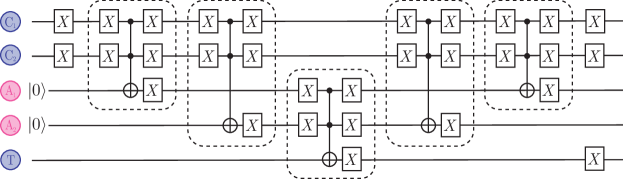
In Figure 8, we showed how an ancilla atom can be used to eliminate -type errors resulting from control atom decay in the implementation of a bias-preserving CNOT gate. Analogously, a bias-preserving Toffoli gate can be implemented by making use of two ancilla atoms which lie on either side of the target atom. This protocol is illustrated in Figure 14.
As with the case of the bias-preserving CNOT, the choice of Rydberg states differs throughout the procedure. By coupling the atoms to during the third gate of Figure 14 and using ancilla atoms on opposite sides of the target atom, we ensure that the ancilla atoms do not interact with each other via Rydberg blockade during this gate; this is important in case one of the ancilla atoms undergoes a radiative decay transition during this gate. On the other hand, the other entangling gates in Figure 14 all use the Rydberg states , due to larger distances between the atoms during these gates. We note that the two control atoms may interact with each other during these four gates if the distance between them is less than one blockade radius, which is different from the case of the third gate. This is acceptable because Rydberg errors can occur during at most one of these four gates, so at least one ancilla atom will generate the correct interaction with the target atom during the third gate.
Appendix H Computing Resource Costs for Rydberg FTQC Protocols
We now provide details on how to obtain the resource costs for Ryd-7 and Ryd-3 presented in Tables 1 and 2.
For the Ryd-7 protocol, each stabilizer measurement requires four two-qubit Rydberg gates in the absence of errors (see Algorithm 1); thus, 24 two-qubit gates are required to measure all stabilizers. If an error occurs, the worst case scenario for the stabilizer measurement is when the first five stabilizers all have eigenvalues, while the very last stabilizer is measured to be . In this case, , , and need to be re-measured, which requires 12 additional two-qubit gates. The logical CCZ gate for Ryd-7 is implemented using 27 physical three-qubit gates in the absence of error, as described in Algorithm 3. The worst case error in this case is a Rydberg leakage error that occurred during the first entangling gate in the final group of Figure 3. In this scenario, identifying the location of the Rydberg leakage error requires up to 18 additional two-qubit gates, while measuring the stabilizers for all three logical qubits would amount to 60 additional two-qubit gates; the correction circuit could require up to two additional three-qubit gates.
In the Ryd-3 protocol, each of the two stabilizer measurements requires two bias-preserving CNOT gates (Figure 1e), and each bias-preserving CNOT gate is broken down to two two-atom gates and one three-atom entangling gate (see Section V.1). Thus, in the absence of error, the stabilizer measurements would require eight two-qubit gates and four three-qubit gates. If an error occurs, the worst case scenario is if the second stabilizer is measured to be ; in this case, both stabilizers need to be re-measured, and the gate cost is doubled. The Ryd-3 CCZ gate can be implemented in a round-robin fashion in the same way as the Ryd-7 CCZ, which is bias-preserving and uses 27 physical three-qubit gates.
Finally, the Ryd-3 Hadamard gate consists of a fault-tolerant, bias-preserving Toffoli gate followed by single-qubit measurements and rotations (Figure 10). The pieceable fault-tolerant Toffoli gate in the Ryd-3 code consists of nine physical bias-preserving Toffoli gates and two rounds of error correction. As discussed above, each round of error correction involves eight two-atom Rydberg gates and four three-atom Rydberg gates. When the data atoms within each logical qubit are indexed as in Figure 15b and we are implementing a logical Toffoli gate between the three qubits , , highlighted in bold, the number of Rydberg gates required to implement each physical Toffoli gate depends on the blockade radius . If the blockade radius is larger than , each physical Toffoli gate can be implemented using two ancilla atoms (one on either side of the target atom) and five three-atom Rydberg gates, as described in Appendix G; this is because the distance between any physical control atom and any ancilla in Figure 14 will always be less than the blockade radius , so the entangling gates can be implemented directly. In this case, each physical Toffoli gate involves five three-atom Rydberg gates, so the total gate count (upon including the QEC steps) is 16 two-atom gates and 53 three-atom gates in the absence of errors. On the other hand, if we wish to reduce the blockade radius requirement to , there are two physical Toffoli gates (corresponding to the choices , and , ), where the distance between one of the physical control atoms and one of the ancilla atoms ( and in Figure 15b) would be too large to directly implement a Rydberg entangling gate required for the physical Toffoli gate. Instead, in place of the first (respectively, second) three-atom Rydberg gate involving , we would implement a Rydberg gate with the same two control atoms and one of the ancilla atoms or , whichever is not involved in the rest of the Figure 14 circuit, followed (respectively, preceded) by a bias-preserving CNOT gate between that ancilla and . These gates can be implemented directly because both and are within the blockade radius of , , , , and . In this way, four extra two-atom gates are required for the logical Toffoli (two for the physical Toffoli with , and two for the physical Toffoli with , ), which increases the total gate count to 20 two-atom gates and 53 three-atom gates in the absence of error, as shown in Table 2. With errors, the worst case scenario is if the final stabilizer measurement in the second round of QEC yields , in which case the stabilizers need to be measured again; this adds another eight two-atom gates and four three-atom gates to the total resource cost.
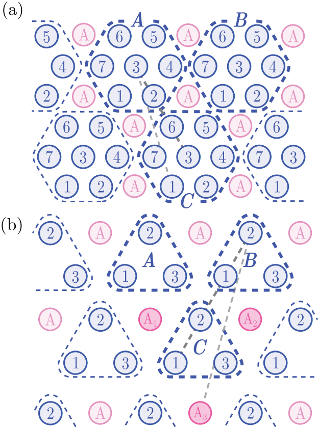
Appendix I Computing Rydberg Blockade Radius Requirements for Rydberg FTQC Protocols
To obtain the blockade radius requirement for the Rydberg FTQC protocols, we must identify each physical qubit with an atom on the lattice, and then determine the maximum distance between two atoms which must interact with each other during a Rydberg gate. When the underlying atoms are placed in a triangular lattice, Figure 15 depicts convenient identifications for both the Ryd-7 and Ryd-3 codes. In this figure, numbers are used indicate the indices of data atoms within each logical qubit. (The index of a physical qubit within each logical qubit is the position, counting from the left, of that qubit in the definition of the logical states; see Equations (6) and (7) for the seven-qubit code, or Equation (12) for the three-qubit code.)
In the Ryd-7 protocol, the blockade radius is defined by the interaction range needed to perform a logical CCZ gate between three neighboring logical qubits such as , , and . Using the specific protocol given in Algorithm 3, which involves 27 physical CCZ gates between atoms , we find the largest interaction range is required to perform the physical CCZ gate between farthest-separated triples such as . For this specific case, the distances between atom pairs are , , and . To apply the three-qubit Rydberg gate as defined in Section II, this would require a blockade radius of . However, this is not entirely necessary for our purposes: instead, it is sufficient that two out of the three distances , , and be less than the blockade radius. To see this, let us suppose, for example, that the distance between the two control atoms and is greater than . In this case, applying the same pulse sequence as illustrated in Figure 2b would result in a three-qubit gate , which can also be obtained from the CCZ gate by single-qubit unitaries ().
The argument above allows the blockade radius requirement for Ryd-7 to be reduced to (thinner, light grey dotted line in Figure 15). In fact, by modifying the implementation of the logical CCZ gate, it is possible to further reduce this requirement to (thicker, dark grey dotted line in Figure 15); this is shown in Appendix J.
In the Ryd-3 protocol, the blockade radius is determined by the interaction range required to implement the logical Toffoli gate between neighboring logical qubits (e.g., , , and in Figure 15). As discussed in Appendix H, there are two possibilities in this case. To directly implement every physical bias-preserving Toffoli gate using the circuit of Figure 14, the distance between and must be less than ; this requires (thinner, light grey dotted line in Figure 15). However, this requirement can be reduced to (thicker, dark grey dotted line in Figure 15) at the expense of four additional two-atom entangling gates per logical Toffoli or Hadamard operation.
Appendix J Blockade Radius Reduction for Ryd-7
To reduce the blockade radius requirement from to in the Ryd-7 protocol, we must modify the implementation of the logical CCZ operation. Recall that Algorithm 3 implements a logical CCZ gate using 27 physical CCZ gates between the first three physical qubits of every logical qubit. This round-robin decomposition makes use of Eq. (11), which we now derive:
| (32) |
To begin the derivation, we first recall that the logical states (6) and (7) of the seven-qubit code have well-defined parity: the number of physical qubits in the state is always even for and odd for . It then follows that the logical CCZ gate can be implemented in a fully round-robin fashion involving all physical qubits
| (33) |
This is because the round-robin implementation results in a phase accumulation for each triple of physical qubits in the state, and the number of such triples is odd if all logical qubits are in the logical state, while it is even if at least one logical qubit is in the state. To reduce this to Eq. (32), we notice that for each choice of and , the product
| (34) |
acts as an identity operation on the logical qubits, because is a stabilizer of the seven-qubit code. We then multiply both sides of Eq. (33) by this operator, and use the fact that all the CCZ gates commute with each other and square to the identity operator. In this way, the product over in the logical CCZ gate can be reduced from to . Because the CCZ gate is symmetric in the three involved qubits, this same argument can be applied to reduce the products over and to obtain Eq. (32).
To reduce the blockade radius requirement from to , we can replace the product (34) by
| (35) |
in our derivation for one of the logical qubits, say qubit . This is because the single-qubit operator is the product of two stabilizers, so the operator (35) also acts trivially on the logical subspace. It follows that
| (36) |
Thus, the 27 physical CCZ gates in Algorithm 3 may be replaced by the 27 CCZ gates used in the right hand side of Eq. (36).
Given the geometrical layout of individual atoms within each logical qubit shown in Figure 15a, we see that the required interaction range for implementing the logical CCZ operation using these 27 gates is smaller than the interaction range required to perform the 27 gates of Algorithm 3. Furthermore, following the observation made in Appendix I, we notice that these physical qubits need not all be within the blockade radius of each other, so long as every physical qubit is within distance of every , and every is within distance of every . This requirement is satisfied for any , as shown in Figure 15a.
Appendix K Square Lattice Geometry for Ryd-3
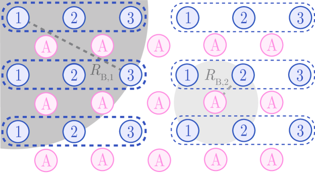
As mentioned in Section V.3 of the main text, the Ryd-3 protocol can also be implemented when the underlying physical atoms are placed on a square lattice. In this case, the data and ancilla atoms are placed on the vertices of the lattice in an alternating fashion as shown in Figure 16. The stabilizer measurements can be implemented as discussed in Section V.2 if the smaller blockade radius satisfies . The logical operation requiring the largest interaction range is the logical CCZ gate
| (37) |
which is implemented from 27 physical CCZ gates. To implement each physical gate, the distance between every pair and must be less than the larger blockade radius , as discussed in Appendix I. The longest such distance is as shown in the dark grey dotted line of Figure 16, so the corresponding blockade radius requirement for this geometry is .
With these blockade radii, the protocols of Section V.2 can be directly applied to perform all logical operations. We note that the higher density of ancilla atoms in this arrangement allows us to implement every physical Toffoli gate in the logical Toffoli operation directly using the circuit of Figure 14, without the need for additional ancilla atoms or CNOT gates (as was the case for two physical Toffoli operations under the triangular lattice geometry). In this way, for the square lattice geometry, the number of two-qubit entangling operations required for the logical Hadamard or Toffoli operations may be reduced by 4 compared to the numbers shown in Table 2.
Appendix L Optical Pumping Procedure for the Bias-Preserving CNOT
To implement the bias-preserving CNOT pulse sequence shown in Figure 7 of the main text, it is important that the optical pumping procedure in the final step pumps only the states to the state, and only the states to the state. This requirement is essential to ensuring that the CNOT does not generate any - or -type errors. For magnetic field regimes typically used in alkali atom Rydberg experiments, this state selectivity may not be straightforward to implement, as the level separation between different states within a single hyperfine manifold may be much smaller than the linewidth of the lasers used for optical pumping. To address this challenge, we can utilize a Rydberg state as a shelving state (due to its long lifetime) to avoid unwanted pumping of (respectively, ) states to (). Thus, in Step 6 of Figure 7, the optical pumping of states into the state can be implemented for 85Rb as follows:
-
1.
Swap the population between the state and the stretched ground state .
-
2.
Swap the population between the state and the ground state .
-
3.
Apply a resonant pulse to shelve any population in the state into the Rydberg state .
-
4.
Use light to excite states in the ground state manifold to the manifold; these excited states decay quickly back to the ground state.
-
5.
Apply resonant pulses and .
-
6.
Repeat Steps 4 and 5 as necessary; after several iterations, all population that started with will be in the state.
-
7.
Repeat Steps 1, 2, and 3.
Because the state can only be populated if a Rydberg error occurred in one of the earlier steps of the bias-preserving CNOT, to leading order in the total error probability, we may assume that the Rydberg state will not decay if it is populated in the above procedure. In this way, the only states that can be populated at the beginning of Step 4 above will be the states, so the optical pumping will work in the same way as the protocol described in Section IV.2 (Figure 5). An analogous procedure can then be applied to pump the states into . In this latter case, it will not be necessary to shelve population in the Rydberg state, as all population will already have been transferred to the state.
References
- Jaksch et al. (2000) D. Jaksch, J. I. Cirac, P. Zoller, S. L. Rolston, R. Cote, and M. D. Lukin, “Fast quantum gates for neutral atoms,” Phys. Rev. Lett. 85, 2208 (2000).
- Lukin et al. (2001) M. D. Lukin, M. Fleischhauer, R. Cote, L. M. Duan, D. Jaksch, J. I. Cirac, and P. Zoller, “Dipole blockade and quantum information processing in mesoscopic atomic ensembles,” Phys. Rev. Lett. 87, 037901 (2001).
- Saffman et al. (2010) M. Saffman, T. G. Walker, and K. Mølmer, “Quantum information with Rydberg atoms,” Rev. Mod. Phys. 82, 2313 (2010).
- Barredo et al. (2016) D. Barredo, S. de Léséleuc, V. Lienhard, T. Lahaye, and A. Browaeys, “An atom-by-atom assembler of defect-free two-dimensional atomic arrays,” Science 354, 1021–1023 (2016).
- Ebadi et al. (2020) S. Ebadi, T. T. Wang, H. Levine, A. Keesling, G. Semeghini, A. Omran, D. Bluvstein, R. Samajdar, H. Pichler, W. W. Ho, S. Choi, S. Sachdev, M. Grener, V. Vuletic, and M. D. Lukin, Quantum Phases of Matter on a 256-Atom Programmable Quantum Simulator, preprint (arXiv, 2020) arXiv:2012.12281 .
- Barredo et al. (2018) D. Barredo, V. Lienhard, S. de Léséleuc, T. Lahaye, and A. Browaeys, “Synthetic three-dimensional atomic structures assembled atom by atom,” Nature 561, 79–82 (2018).
- Barredo et al. (2020) D. Barredo, V. Lienhard, P. Scholl, S. de Léséleuc, T. Boulier, A. Browaeys, and T. Lahaye, “Three-dimensional trapping of individual Rydberg atoms in ponderomotive bottle beam traps,” Phys. Rev. Lett. 124, 023201 (2020).
- Bernien et al. (2017) H. Bernien, S. Schwartz, A. Keesling, H. Levine, A. Omran, H. Pichler, S. Choi, A. S. Zibrov, M. Endres, M. Greiner, and V. Vuletic, “Probing many-body dynamics on a 51-atom quantum simulator,” Nature 551, 579–584 (2017).
- Levine et al. (2018) H. Levine, A. Keesling, A. Omran, H. Bernien, S. Schwartz, A. S. Zibrov, M. Endres, M. Greiner, V. Vuletic, and M. D. Lukin, “High-fidelity control and entanglement of Rydberg atom qubits,” Phys. Rev. Lett. 121, 123603 (2018).
- Labuhn et al. (2016) H. Labuhn, D. Barredo, S. Ravets, S. de Léséleuc, M. Macri, T. Lahaye, and A. Browaeys, “Tunable two-dimensional arrays of single Rydberg atoms for realizing quantum ising models,” Nature 534, 667–70 (2016).
- Maller et al. (2015) K. M. Maller, M. T. Lichtman, T. Xia, Y. Sun, M. J. Piotrowicz, A. W. Carr, L. Isenhower, and M. Saffman, “Rydberg-blockade controlled-not gate and entanglement in a two-dimensional array of neutral-atom qubits,” Phys. Rev. A 92, 022336 (2015).
- Levine et al. (2019) H. Levine, A. Keesling, G. Semeghini, A. Omran, T. T. Wang, S. Ebadi, H. Bernien, M. Greiner, V. Vuletic, H. Pichler, and M. D. Lukin, “Parallel implementation of high-fidelity multiqubit gates with neutral atoms,” Phys. Rev. Lett. 123, 170503 (2019).
- Graham et al. (2019) T. M. Graham, M. Kwon, B. Grinkemeyer, Z. Marra, X. Jiang, M. T. Lichtman, Y. Sun, M. Ebert, and M. Saffman, “Rydberg-mediated entanglement in a two-dimensional neutral atom qubit array,” Phys. Rev. Lett. 123, 230501 (2019).
- Kim et al. (2018) H. Kim, Y. J. Park, K. Kim, H.-S. Sim, and J. Ahn, “Detailed balance of thermalization dynamics in Rydberg-atom quantum simulators,” Phys. Rev. Lett. 120, 180502 (2018).
- Keesling et al. (2019) A. Keesling, A. Omran, H. Levine, H. Bernien, H. Pichler, S. Choi, R. Samajdar, S. Schwartz, P. Silvi, S. Sachdev, P. Zoller, M. Endres, M. Greiner, V. Vuletic, and M. D. Lukin, “Quantum Kibble-Zurek mechanism and critical dynamics on a programmable Rydberg simulator,” Nature 568, 207–211 (2019).
- Omran et al. (2019) A. Omran, H. Levine, A. Keesling, G. Semeghini, T. T. Wang, S. Ebadi, H. Bernien, A. S. Zibrov, H. Pichler, S. Choi, J. Cui, M. Rossignolo, P. Rembold, S. Montangero, T. Calarco, M. Endres, M. Greiner, V. Vuletic, and M. D. Lukin, “Generation and manipulation of Schrödinger cat states in Rydberg atom arrays,” Science 365, 570–574 (2019).
- Semeghini et al. (2021) G. Semeghini, H. Levine, A. Keesling, S. Ebadi, T. T. Wang, D. Bluvstein, R. Verresen, H. Pichler, M. Kalinowski, R. Samajdar, A. Omran, S. Sachdev, A. Vishwanath, M. Greiner, V. Vuletić, and M. D. Lukin, “Probing topological spin liquids on a programmable quantum simulator,” Science 374, 1242–1247 (2021).
- Bluvstein et al. (2021a) D. Bluvstein, H. Levine, G. Semeghini, T. T. Wang, S. Ebadi, M. Kalinowski, A. Keesling, N. Maskara, H. Pichler, M. Greiner, V. Vuletic, and M. D. Lukin, A quantum processor based on coherent transport of entangled atom arrays, preprint (arXiv, 2021) arXiv:2112.03923 .
- Nielsen and Chuang (2000) M. A. Nielsen and I. Chuang, Quantum Computation and Quantum Information (Cambridge University Press, 2000).
- Shor (1996) P. W Shor, “Fault-tolerant quantum computation,” in Proceedings of 37th Conference on Foundations of Computer Science (IEEE, 1996) pp. 56–65.
- Kitaev (2003) A. Y. Kitaev, “Fault-tolerant quantum computation by anyons,” Ann. Phys. 303, 2–30 (2003).
- Gottesman (2010) D. Gottesman, “An introduction to quantum error correction and fault-tolerant quantum computation,” in Quantum Information Science and its Contributions to Mathematics, Proc. Symposium in Applied Math. (American Mathematical Society, Providence, RI, 2010) pp. 13–56.
- Yoder and Kim (2017) T. J. Yoder and I. H. Kim, “The surface code with a twist,” Quantum 1, 2 (2017).
- Chao and Reichardt (2018a) R. Chao and B. W. Reichardt, “Quantum error correction with only two extra qubits,” Phys. Rev. Lett. 121, 050502 (2018a).
- Chao and Reichardt (2018b) R. Chao and B. W. Reichardt, “Fault-tolerant quantum computation with few qubits,” npj Quantum Information 4, 42 (2018b).
- Reichardt (2018) B. W. Reichardt, Fault-tolerant quantum error correction for Steane’s seven-qubit color code with few or no extra qubits, preprint (arXiv, 2018) arXiv:1804.06995 .
- Chamberland and Beverland (2018) C. Chamberland and M. E. Beverland, “Flag fault-tolerant error correction with arbitrary distance codes,” Quantum 2, 53 (2018).
- Chao and Reichardt (2020) R. Chao and B. W. Reichardt, “Flag fault-tolerant error correction for any stabilizer code,” PRX Quantum 1, 010302 (2020).
- Michael et al. (2016) M. H. Michael, M. Silveri, R. T. Brierley, V. V. Albert, J. Salmilehto, L. Jiang, and S. M. Girvin, “New class of quantum error-correcting codes for a bosonic mode,” Phys. Rev. X 6, 031006 (2016).
- Chamberland et al. (2020) C. Chamberland, K. Noh, P. Arrangoiz-Arriola, E. T. Campbell, C. T. Hann, J. Iverson, H. Putterman, T. C. Bohdanowicz, S. T. Flammia, A. Keller, G. Refael, J. Preskill, L. Jiang, A. H. Safavi-Naeini, O. Painter, and F. G. S. L. Brandão, Building a fault-tolerant quantum computer using concatenated cat codes, preprint (2020) arXiv:2012.04108 .
- Yoder et al. (2016) T. J. Yoder, R. Takagi, and I. L. Chuang, “Universal fault-tolerant gates on concatenated stabilizer codes,” Phys. Rev. X 6, 031039 (2016).
- Bravyi and Kitaev (2005) S. Bravyi and A. Kitaev, “Universal quantum computation with ideal clifford gates and noisy ancillas,” Phys. Rev. A 71, 022316 (2005).
- Nigg et al. (2014) D. Nigg, M. Müller, E. A. Martinez, P. Schindler, M. Hennrich, T. Monz, M. A. Martin-Delgado, and R. Blatt, “Quantum computations on a topologically encoded qubit,” Science 345, 302–305 (2014).
- Rosenblum et al. (2018) S. Rosenblum, P. Reinhold, M. Mirrahimi, L. Jiang, L. Frunzio, and R. J. Schoelkopf, “Fault-tolerant detection of a quantum error,” Science 361, 266–270 (2018).
- Campagne-Ibarcq et al. (2020) P. Campagne-Ibarcq, A. Eickbusch, S. Touzard, E. Zalys-Geller, N. E. Frattini, V. V. Sivak, P. Reinhold, S. Puri, S. Shankar, R. J. Schoelkopf, et al., “Quantum error correction of a qubit encoded in grid states of an oscillator,” Nature 584, 368–372 (2020).
- de Neeve et al. (2020) B. de Neeve, T. L. Nguyen, T. Behrle, and J. Home, Error correction of a logical grid state qubit by dissipative pumping, preprint (arXiv, 2020) arXiv:2010.09681 .
- Egan et al. (2021) L. Egan, D. M. Debroy, C. Noel, A. Risinger, D. Zhu, D. Biswas, M. Newman, M. Li, K. R. Brown, M. Cetina, and C. Monroe, Fault-Tolerant Operation of a Quantum Error-Correction Code, preprint (arXiv, 2021) arXiv:2009.11482 .
- Steane (1996) A. Steane, “Multiple-particle interference and quantum error correction,” Proc. R. Soc. Lond. A. 452, 2551–2577 (1996).
- Isenhower et al. (2011) L. Isenhower, M. Saffman, and K. Mølmer, “Multibit CkNOT quantum gates via Rydberg blockade,” Quantum Inf. Process. 10, 755–770 (2011).
- Auger et al. (2017) J. M. Auger, S. Bergamini, and D. E. Browne, “Blueprint for fault-tolerant quantum computation with rydberg atoms,” Phys. Rev. A 96, 052320 (2017).
- Shi (2003) Y. Shi, “Both Toffoli and Controlled-NOT need little help to do universal quantum computation,” Quantum Information and Computation 3, 84–92 (2003).
- Guillaud and Mirrahimi (2019) J. Guillaud and M. Mirrahimi, “Repetition cat qubits for fault-tolerant quantum computation,” Phys. Rev. X 9, 041053 (2019).
- Zeng et al. (2017) Y. Zeng, P. Xu, X. He, Y. Liu, M. Liu, J. Wang, D. J. Papoular, G. V. Shlyapnikov, and M. Zhan, “Entangling two individual atoms of different isotopes via Rydberg blockade,” Phys. Rev. Lett. 119, 160502 (2017).
- Singh et al. (2021) K. Singh, S. Anand, A. Pocklington, J. T. Kemp, and H. Bernien, A dual-element, two-dimensional atom array with continuous-mode operation, preprint (arXiv, 2021) arXiv:2110.05515 .
- Xu et al. (2021) W. Xu, A. V. Venkatramani, S. H. Cantu, T. Šumarac, V. Klüsener, M. D. Lukin, and V. Vuletić, Fast Preparation and Detection of a Rydberg Qubit using Atomic Ensembles, preprint (arXiv, 2021) arXiv:2105.11050 .
- Madjarov et al. (2020) I. S. Madjarov, J. P. Covey, A. L. Shaw, J. Choi, A. Kale, A. Cooper, H. Picher, V. Schkolnik, J. R. Williams, and M. Endres, “High-fidelity entanglement and detection of alkaline-earth Rydberg atoms,” Nat. Phys. (2020), 10.1038/s41567-020-0903-z.
- Wilson et al. (2019) J. Wilson, S. Saskin, Y. Meng, S. Ma, R. Dilip, A. Burgers, and J. Thompson, Trapped arrays of alkaline earth Rydberg atoms in optical tweezers, preprint (arXiv, 2019) arXiv:1912.08754 .
- Vandersypen and Chuang (2005) L. M. K. Vandersypen and I. L. Chuang, “Nmr techniques for quantum control and computation,” Rev. Mod. Phys. 76, 1037–1069 (2005).
- Beterov et al. (2009) I. I. Beterov, I. I. Ryabtsev, D. B. Tretyakov, and V. M. Entin, “Quasiclassical calculations of blackbody-radiation-induced depopulation rates and effective lifetimes of Rydberg , , and alkali-metal atoms with ,” Phys. Rev. A 79, 052504 (2009).
- Carmichael (1993) H. J. Carmichael, An Open Systems Approach to Quantum Optics (Springer, 1993).
- Preskill (1998) J. Preskill, “Quantum information and computation,” (1998), Lecture Notes for Physics 229, California Institute of Technology.
- Cooke and Gallagher (1980) W. E. Cooke and T. F. Gallagher, “Effects of blackbody radiation on highly excited atoms,” Phys. Rev. A 21, 588 (1980).
- Löw et al. (2012) R. Löw, H. Weimer, J. Nipper, J. B. Balewski, B. Butscher, H. P. Büchler, and T. Pfau, “An experimental and theoretical guide to strongly interacting Rydberg gases,” J. Phys. B.: At. Mol. Opt. Phys. 45, 113001 (2012).
- Wu et al. (2022) Y. Wu, S. Kolkowitz, S. Puri, and J. D. Thompson, Erasure conversion for fault-tolerant quantum computing in alkaline earth Rydberg atom arrays, preprint (arXiv, 2022) arXiv:2201.03540 .
- Wang et al. (2021) P. Wang, C.-Y. Luan, M. Qiao, M. Um, J. Zhang, Y. Wang, X. Yuan, M. Gu, J. Zhang, and K. Kim, “Single ion qubit with estimated coherence time exceeding one hour,” Nature Communications 12, 1–8 (2021).
- Cohen (2003) J. S. Cohen, “Effect of tunneling on ionization of rydberg states in intense fields: Hydrogenic atoms,” Phys. Rev. A 68, 033409 (2003).
- Beguin (2013) L. Beguin, “Measurement of the van der waals interaction between two Rydberg atoms,” (2013).
- Puri et al. (2019) S. Puri, L. St-Jean, J. A. Gross, A. Grimm, N. E. Frattini, P. S. Iyer, A. Krishna, S. Touzard, L. Jiang, A. Blais, S. T. Flammia, and S. M. Girvin, Bias-preserving gates with stabilized cat qubits, preprint (arXiv, 2019) arXiv:1905.00450 .
- Bluvstein et al. (2021b) D. Bluvstein, A. Omran, H. Levine, A. Keesling, G. Semeghini, S. Ebadi, T. T. Wang, A. A. Michailidis, N. Maskara, W. W. Ho, S. Choi, M. Serbyn, M. Greiner, V. Vuletic, and M. D. Lukin, “Controlling quantum many-body dynamics in driven Rydberg atom arrays,” Science (2021b), 10.1126/science.abg2530.
- Bergschneider et al. (2018) A. Bergschneider, V. M. Klinkhamer, J. H. Becher, R. Klemt, G. Zürn, P. M. Preiss, and S. Jochim, “Spin-resolved single-atom imaging of in free space,” Phys. Rev. A 97, 063613 (2018).
- Steck (2019) D. A. Steck, “Rubidium 87 D line data,” (2019), available online at http://steck.us/alkalidata (revision 2.2.1, 21 November 2019).
- Carruthers and Nieto (1965) P. Carruthers and M. M. Nieto, “Coherent states and the forced quantum oscillator,” American Journal of Physics 33, 537–544 (1965).
- Boyd et al. (2007) M. M. Boyd, T. Zelevinsky, A. D. Ludlow, S. Blatt, T. Zanon-Willette, S. M. Foreman, and J. Ye, “Nuclear spin effects in optical lattice clocks,” Phys. Rev. A 76, 022510 (2007).
- Ludlow et al. (2015) A. D. Ludlow, M. M. Boyd, J. Ye, E. Peik, and P. O. Schmidt, “Optical atomic clocks,” Rev. Mod. Phys. 87, 637–701 (2015).
- Hayes et al. (2020) D. Hayes, D. Stack, B. Bjork, A. C. Potter, C. H. Baldwin, and R. P. Stutz, “Eliminating leakage errors in hyperfine qubits,” Phys. Rev. Lett. 124, 170501 (2020).
- Bravyi and Kitaev (1998) S. B. Bravyi and A. Y. Kitaev, Quantum codes on a lattice with boundary, preprint (arXiv, 1998) arXiv:quant-ph/9811052 .
- Fowler et al. (2012) A. G. Fowler, M. Mariantoni, J. M. Martinis, and A. N. Cleland, “Surface codes: Towards practical large-scale quantum computation,” Phys. Rev. A 86, 032324 (2012).
- Bombin and Martin-Delgado (2006) H. Bombin and M. A. Martin-Delgado, “Topological quantum distillation,” Phys. Rev. Lett. 97, 180501 (2006).
- Bombin and Martin-Delgado (2007) H. Bombin and M. A. Martin-Delgado, “Topological computation without braiding,” Phys. Rev. Lett. 98, 160502 (2007).
- Terhal (2015) B. M. Terhal, “Quantum error correction for quantum memories,” Rev. Mod. Phys. 87, 307–346 (2015).
- Tuckett et al. (2018) D. K. Tuckett, S. D. Bartlett, and S. T. Flammia, “Ultrahigh error threshold for surface codes with biased noise,” Phys. Rev. Lett. 120, 050505 (2018).
- Kaulakys (1995) B. Kaulakys, “Consistent analytical approach for the quasi-classical radial dipole matrix elements,” J. Phys. B: At. Mol. Opt. Phys. 28, 4963 (1995).
- Kamta et al. (1998) G. Lagmago Kamta, S. G. Nana Engo, M. G. Kwato Njock, and B. Oumarou, “Consistent description of Klein-Gordon dipole matrix elements,” J. Phys. B.: AT. Mol. Opt. Phys. 31, 963 (1998).