Sensitivity of third-generation interferometers to extra polarizations
in the Stochastic Gravitational Wave Background
Abstract
When modified theories of gravity are considered, at most six gravitational wave polarization modes are allowed and classified in tensor modes, the only ones predicted by General Relativity (GR), along with additional vector and scalar modes. Therefore, gravitational waves represent a powerful tool to test alternative theories of gravitation. In this paper, we forecast the sensitivity of third-generation ground-based interferometers, Einstein Telescope and Cosmic Explorer, to non-GR polarization modes focusing on the stochastic gravitational wave background. We consider the latest technical specifications of the two independent detectors and the full network in order to estimate both the optimal signal-to-noise ratio and the detectable energy density limits relative to all polarization modes in the stochastic background for several locations on Earth and orientations of the two observatories. By considering optimal detector configurations, we find that in 5 years of observation the detection limit for tensor and extra polarization modes could reach , depending on the network configuration and the stochastic background (i.e. if only one among vector and scalar modes exists or both are present). This means that the network sensitivity to different polarization modes can be approximately improved by a factor with respect to second-generation interferometers. We finally discuss the possibility of breaking the scalar modes degeneracy by considering both detectors angular responses to sufficiently high gravitational wave frequencies.
I Introduction
In 2016 it was announced by the LIGO-Virgo collaboration that gravitational waves (GWs) from the merging of a binary black hole system were directly observed for the first time Abbott et al. (2016a, b) and since then, other GWs related to astrophysical processes have been detected (see e.g. Abbott et al. (2016c); Scientific et al. (2017); Abbott et al. (2017a, b, c, 2020a)). All these events provided a successful method to test possible deviations from General Relativity (GR) and confirmed that Einstein’s theory is the most accurate and well-tested theory of gravitation we have. Nevertheless the last century saw the rise of a wide number of alternative theories (see e.g. Brans and Dicke (1961a); Sotiriou and Faraoni (2010); De Felice and Tsujikawa (2010a); Hellings and Nordtvedt Jr (1973); Will and Nordtvedt Jr (1972)), also, e.g., in connection with a possible explanation of the late time acceleration of the universe De Felice and Tsujikawa (2010b); Capozziello and De Laurentis (2011); Clifton et al. (2012) or to model the early universe expansion Heisenberg (2018); Heisenberg et al. (2018). When such generic metric theories of gravity are considered, at most six gravitational wave polarization modes are allowed: two tensor modes (usually called tensor-plus and tensor-cross), the only ones permitted by GR, two scalar modes (scalar-breathing and scalar-longitudinal) and two vector modes (vector-x and vector-y). Not all alternative theories of gravity are excluded by today direct GW observations (see e.g. Will (2014); de Rham et al. (2017); Will (2018); Ezquiaga and Zumalacárregui (2018) for a detailed overview), therefore the presence or absence of such extra polarization modes provides a useful tool to test and eventually extend the theory of GR, opening the way to other theoretical models.
A search for non-GR polarization modes may be pursued through the detection of a stochastic gravitational wave background (SGWB) Maggiore (2008, 2018); Allen and Romano (1999) which is among the expected targets of future generation laser interferometers 111See also recent constraints on the polarization of GWs from single events Abbott et al. (2019, 2017b, 2020b). In order to separate tensor, vector and scalar polarization modes in terms of the corresponding energy density contributions to the SGWB, the correlation analysis Romano and Cornish (2017) represents a useful tool: indeed, the polarization modes separation issue was presented in detail by Nishizawa et al. Nishizawa et al. (2009) for second-generation ground-based interferometers (e.g. the two LIGO observatories, Virgo and KAGRA), where it was shown that energy density contributions from tensor, vector and scalar polarization modes to the SGWB energy density can be isolated from each other considering a network involving at least three GW detectors. Despite the fact that the limited sensitivity of current detectors has not allowed to directly measure any SGWB yet, the LIGO-Virgo collaboration recently provided upper limits for tensor, vector and scalar modes energy densities , and Abbott et al. (2021). Additionally, the next upgrade LIGO A for the two observatories in North America Barsotti et al. (2018) and the addition of the planned IndIGO interferometer in India Unnikrishnan (2013) might further improve the current constraints (see also recent work on SGWBs with NANOGrav Arzoumanian et al. (2016); Chen et al. (2021); Arzoumanian et al. (2020)).
The better sensitivity of future third-generation laser interferometers will most probably allow to detect the SGWB and so to possibly probe GW extra polarizations. Both the European project Einstein Telescope 222http://www.et-gw.eu/ and the american project Cosmic Explorer 333https://cosmicexplorer.org/ are two additional ground-based observatories which are going to be built in the upcoming future. Besides interferometers on Earth, several space-based GW detectors such as LISA Amaro-Seoane et al. (2017), the Japanese project DECIGO Ando et al. (2010); Kawamura et al. (2011) and Chinese projects TianQin Luo et al. (2016) and Taiji Hu and Wu (2017) are planned to be launched in the near future. Optimistically starting among late 2020s and 2030s, interplays among these detectors are expected to resolve GW sources with incredible precision while exploring different frequency ranges 444See e.g. Barish et al. (2020) for recent work on “midband” detectors which are expected to close the frequency gap between space-based and ground-based interferometers., making the following decades a promising period for the study of GWs (see e.g. Bartolo et al. (2016); Caprini et al. (2019); Baker et al. (2019); Maggiore et al. (2020); Barausse et al. (2020); Contaldi et al. (2020); Orlando et al. (2021); Sathyaprakash et al. (2019); Flauger et al. (2021); Dall’Armi et al. (2021)).
In a recent work by Omiya and Seto Omiya and Seto (2020), the possibility of detecting vector and scalar polarization modes in a SGWB exploiting the LISA-Taiji network has been explored, leading to the theoretical expectation that ten years of observation could provide much smaller upper limits for the detectable energy density and than the ones provided by Abbott et al. (2021). However, due to LISA and Taiji triangular topology and sensitivity, extra polarization modes can be isolated only for a SGWB made of tensor and only one among vector or scalar modes. On the other hand, to date a detailed study for third-generation ground-based interferometers (i.e. Einstein Telescope and Cosmic Explorer) in order to estimate the sensitivity to non-GR polarizations in the SGWB and to distinguish different polarization modes considering the detector latest technical specifications was still missing 555Outside the SGWB context, see Takeda et al. (2019) for recent work on ET and CE to test extra polarization modes from compact binary mergers..
In this work we first investigate the connection between the Einstein Telescope topology (which will most likely consist of three V-shaped interferometers displaced in a triangular way) and extra polarization modes. Indeed, in terms of tensor modes, a well-known result is that the full Einstein Telescope detector would be sensitive to GWs coming from each direction in the sky Regimbau et al. (2012), in contrast to single and traditional L-shaped interferometers Romano and Cornish (2017). We further extend this result to vector and scalar modes, showing that more isotropic detector angular responses can be also obtained, with the only “blind” direction being the one orthogonal to the detector plane. Next, through correlation analysis Allen and Romano (1999); Romano and Cornish (2017), we address the polarization modes separation problem Nishizawa et al. (2009); Omiya and Seto (2020) with GW interferometers and we investigate different possible SGWBs when scalar, vector or both non-GR polarization classes are present along with usual tensor modes. In particular, we focus on third-generation ground-based detectors and we first carry out an analysis of how different angular separations on Earth between the Einstein Telescope and Cosmic Explorer impact on the SNR and we look for optimal orientations of both observatories for each case. Second, we investigate the possibility of having two Cosmic Explorer-like detectors replacing the two LIGO observatories in North America both in location and orientation and we further assume the Einstein Telescope to be placed either in Sardinia (Italy), or the border region between the Netherlands, Belgium and Germany, which are two possible sites currently under investigation Note (1). In general, we find that considering the Einstein Telescope-Cosmic Explorer network, detection limits for the detectable energy density , with , and (assuming a frequency independent energy density spectrum for the SGWB), would approximately range from to for 5 years of observation depending on the network configuration and the stochastic background considered (i.e. if one or both non-GR polarization classes are present). Finally, we focus on the Einstein Telescope and Cosmic Explorer in order to break the so-called scalar modes degeneracy. The latter implies that for sufficiently low GW frequencies, detector angular responses to breathing and longitudinal polarization modes differ only for a constant factor, making the two scalar modes indistinguishable for a given interferometer (see e.g. Romano and Cornish (2017)). This is no longer true when we consider GWs whose frequencies are higher than a characteristic value inversely proportional to the interferometer arm length: therefore, in analogy e.g. to Liu et al. (2020a); Liang et al. (2019) for space-based detectors, we discuss this scenario focusing on the Einstein Telescope and Cosmic Explorer, while obtaining frequency-dependent angular responses and breaking the degeneracy.
The paper is structured as follows. In section II, we define all possible GW polarization modes to further introduce the corresponding detector angular responses. In section III, we consider both Einstein Telescope and Cosmic Explorer angular responses in relation to their different topologies: we recall some differences and similarities between the two and we finally compute and investigate the Einstein Telescope network angular response to extra polarization modes. In section IV, we first retrace the fundamental steps of correlation analysis in order to detect a SGWB made of only tensor modes, then we present our forecasts for the detection limit of the SGWB detectable energy density working with the new generation of ground-based interferometers. We further extend these results in sections V, VI and VII to a SGWB made of tensor and -polarization modes (with being vector or scalar) and to a SGWB made of tensor, vector and scalar polarization modes at the same time: in particular, we explore several network layouts involving the Einstein Telescope and Cosmic Explorer and, for each case considered, we appropriately provide our results for the detection limit of the SGWB detectable energy density contributions for non-GR polarization modes. In section VIII, we consider detector angular responses to GWs with sufficiently high frequencies in order to discuss the possible breaking of the degeneracy between scalar polarization modes using both the Einstein Telescope and Cosmic Explorer. Finally, in section IX, we summarize our results and we draw out conclusions.
We fully focus on the sensitivity of third-generation ground-based interferometers to the SGWB. Extending the result obtained for tensor modes Regimbau et al. (2012), we compute and discuss a new expression for the Einstein Telescope network response to vector and scalar polarization modes. Moreover, in comparison to results already available in literature for second-generation ground-based interferometers Allen and Romano (1999); Nishizawa et al. (2009); Abbott et al. (2021) and space-based ones Omiya and Seto (2020), for the first time (to our knowledge) we investigate in depth possible setups and proposed locations for the Einstein Telescope and Cosmic Explorer, along with the corresponding detector sensitivities to GWs available to date, in order to carry on a detailed analysis for the detection of the SGWB (in the presence or absence of one or both extra polarization modes) and to provide forecasted limits on the detectable energy density contributions to the SGWB for tensor, vector and scalar modes. We also briefly discuss the possibility of breaking the scalar modes degeneracy given the GW frequency ranges to which the Einstein Telescope and Cosmic Explorer are sensitive, that up to now was only explored for space-based detectors Liu et al. (2020a); Liang et al. (2019).
II GW polarization modes
In this section we briefly discuss the detector response to each possible GW polarization Nishizawa et al. (2009); Romano and Cornish (2017). We assume the existence of both tensor and extra (i.e. vector and scalar) GW polarization modes and we further decompose the spatial metric perturbation as follows Maggiore (2008, 2018)
| (1) | |||||
where and are the GW amplitude and corresponding polarization tensor respectively for = (tensor-plus), (tensor-cross), (vector-x), (vector-y), (scalar-breathing) and (scalar-longitudinal). The unit vector is defined on the 2-sphere and denotes the general GW direction, which we further assume to be traveling at the speed of light Liu et al. (2020b). Let us consider the following orthonormal coordinate system
where unit vectors and identify the plane where the GW detector lies, while denotes the orthogonal direction to such plane. Let us further consider a second orthonormal coordinate system rotated by angles given by
Since we wish to consider the most general choice of coordinates, we perform a plane-rotation by an angle , the so-called polarization angle, around the axis identified by the unit vector , thus we get
This allows us to choose the orthonormal basis to give a proper expression to polarization tensors
-
•
Tensor modes:
(2) -
•
Vector modes:
(3) -
•
Scalar modes:
(4)
The detector response to incoming GWs is represented by its angular pattern functions (APFs), which are given by
| (5) |
where is the so-called detector tensor containing information on the detector geometry. For a given interferometer
| (6) |
where and are the unit vectors directed along each interferometer arm. Note that the expression given in Eq.(6) becomes valid only while considering GW frequencies lower than a characteristic value, which is inversely proportional to the interferometer arm length (). Although this assumption is fairly good in the cross-correlation scenario, third-generation ground-based interferometers are expected to be sensitive to GW frequencies higher than their respective characteristic frequency : whenever the low-frequency limit is no longer valid, the detector tensor expression is modified and a detector transfer functions need to be taken into account (see e.g. Schilling (1997)). In section VIII we discuss the detector response to GW frequencies , while in the rest of this paper we always take the low-frequency limit to be valid: we shall briefly mention why this assumption is possible along the way.
III Third-Generation ground-based Interferometers
In this section, we quickly retrace the well-known results available in literature for detector angular responses (see e.g. Romano and Cornish (2017); Cutler (1998)) to each polarization mode ( = , , , , and ), then we discuss the detector angular response to joined tensor, vector and scalar polarization modes Schutz (2011) with the third-generation of ground-based interferometers, which consists of two upcoming detectors: the European project Einstein Telescope Maggiore et al. (2020); Punturo et al. (2010); Note (1) and the American project Cosmic Explorer Reitze et al. (2019a); Note (2). Some well-known results for tensor modes are finally extended to extra polarization modes for the first time.
III.1 The Einstein Telescope

The Einstein Telescope (ET) observatory will most likely consist of three V-shaped interferometers (throughout the paper, we refer to ET three interferometers as ETA, ETB and ETC) with arm length km (meaning Hz) and opening angle of displaced in a triangular way Note (1) as shown in Fig.1. In contrast to L-shaped interferometers, a triangular layout is preferred since it would be equally sensitive to plus and cross polarization modes and, as we shall see, would provide a more isotropic angular response in terms of tensor polarization modes. Moreover, in order to compute the detector angular response to each GW polarization mode, in this case we need to set unit vectors directed along each detector arm for every possible interferometer
We further consider Eq.(5) to compute APFs Romano and Cornish (2017) relative to the single detector ETA, finding the following expressions
-
•
Tensor modes:
(7) (8) -
•
Vector modes:
(9) (10) -
•
Scalar modes:
(11) (12)
Note that breathing and longitudinal APFs differ only for a multiplicative constant factor, thus making the two scalar polarization modes degenerate and indistinguishable for a single ET detecor. In order to compute the APFs relative to ETB and ETC for each polarization mode we can simply exploit the following identities (given ET triangular topology)
| (13) |
with = , , , , and . Since we have three interferometers, we can consider ET as a network to compute its joint angular response Schutz (2011) to tensor and, for the first time, to extra polarization modes
| (14) | |||||
| (15) | |||||
| (16) | |||||
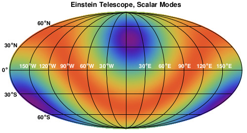
Plots of square roots of ET joint responses for tensor, vector and scalar polarization modes are shown in Fig.2.


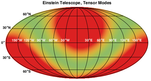
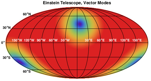
In terms of tensor modes, ET sensitivity has already been investigated in literature Regimbau et al. (2012): the network optimal response is given by , while the minimum value is given by . This also means that ET presents no blind directions, therefore the network has full sky-coverage. Additionally, ET averaged response over the solid angle is given by = . Here, we extend these results to vector and scalar modes: optimal responses are given by and , where the only blind direction is the one orthogonal to the detector plane identified by
Finally, ET averaged responses to extra polarization modes are given by = and = . Note that ET angular joint response to tensor modes is -independent, but it presents cylindrical symmetry with respect to the orthogonal direction to the detector plane. These properties are a consequence of ET triangular topology and, considering Eqs.(15) and (16), it is straightforward to extend them to extra polarization modes.
III.2 The Cosmic Explorer

The Cosmic Explorer (CE) observatory will consist of one single L-shaped interferometer with arm length km ( times the length of LIGO and times the length of one Einstein Telescope interferometer) and opening angle of as shown in Fig.3 and a characteristic frequency Hz. In order to compute the detector angular response to each GW polarization mode we need to set the unit vectors directed to each detector arm
Then, from Eq.(5), we get the following APFs Romano and Cornish (2017)
-
•
Tensor modes:
(17) (18) -
•
Vector modes:
(19) (20) -
•
Scalar modes:
(21) (22)
Despite the fact we are considering a GW interferometer with a bigger opening angle with respect to ET, once again the two scalar modes differ only for a constant factor and they are still degenerate. We shall see in section VIII that the choice of the interferometer opening angle does not break the degeneracy in the low-frequency limit. We further compute the CE angular response to joined tensor, vector and scalar polarization modes in the following way
| (25) | |||||
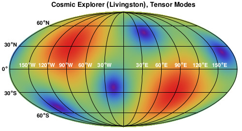
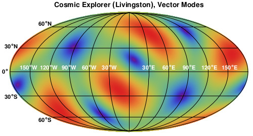
These responses are also called detector antenna power pattern functions (APPFs) for tensor, vector and scalar modes Schutz (2011) and plots of their corresponding square root are shown in Fig.4.


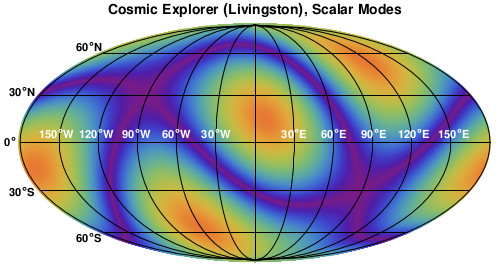
Note that also CE angular responses to tensor, vector and scalar polarization modes are independent from the polarization angle . Optimal values for APPFs are given by , and . However, there are clearly some directions to which the detector results utterly insensitive Romano and Cornish (2017): these blind spots are given by
| (26) |
| (27) |
| (28) |
Similarly to what was done for ET, we compute the values of the averaged angular responses over the solid angle , which are given by = , = and = . In terms of tensor modes, if we compare the average response of CE to the one we obtained for ET, we see the latter is smaller by a factor = , but its three detectors enhance its response by a factor Regimbau et al. (2012). Moreover, this enhancement is due to the detector geometry, rather than the polarization modes considered: indeed, our results show this is also true for vector and scalar polarization modes, therefore we have
| (29) |
for and . At the time of writing, both Einstein Telescope and CE projects are still being discussed and we have very little or no information on their definitive location and orientation, although we know that two preferred sites for ET are the Sardinia island in Italy and the border region between the Netherlands, Belgium and Germany Note (1). Therefore, we further consider an Earth-based coordinate system and we show the plot relative to CE (which we assume to replace the LIGO Livingston observatory both in location and orientation) APPFs and to ET (located in the Sardinia island in Italy) joint angular responses to tensor, vector and scalar polarization modes in Fig.5: note how ET triangular topology visibly provides a more isotropic angular response to tensor modes, in contrast to a single L-shaped interferometer. As we discussed, indeed this also applies to extra polarization modes, where the number of insensitive directions to incoming GWs is reduced to one (i.e. the orthogonal direction to the detector plane).






IV Correlation Analysis
GWs have tensorial nature, though we expect the detector output to be given by a scalar quantity expressed as the sum of two terms Maggiore (2008); Romano and Cornish (2017): the first one given by , representing the true GW signal, and the second one given by , representing the detector noise
| (30) |
In particular, for a detector located in , the GW signal is expressed as
| (31) | |||||
where in the second equality we used Eq.(5). It is usually more convenient to switch to the frequency domain, thus expressing the signal as
| (32) |
where is the Fourier transform of Eq.(31) given by
| (33) |
and is the Fourier transform of the noise term. In the rest of this section we want to understand how GWs can be detected through the correlation analysis technique while focusing on a SGWB Romano and Cornish (2017) which we assume to be stationary, unpolarized and in first approximation both gaussian and isotropic 666for some recent works about non-Gaussianities and anisotropies of the SGWB, see e.g. Bartolo et al. (2018, 2019, 2020a, 2020b); Dall’Armi et al. (2021).. Whenever these four assumptions can be taken to be valid, all SGWB statistical properties are characterized by the so-called two-point correlator Romano and Cornish (2017)
| (34) | |||||
where denotes the ensemble average, while is a real function called power spectral density, it is defined for each polarization mode and it has dimensions Hz-1. In order to characterize the SGWB energy density, the energy density per logarithmic frequency bin normalized by the critical energy density of the Universe is introduced for each polarization mode Maggiore (2008)
| (35) |
where and is the Hubble constant. Moreover, there exists a precise relation between the two functions and given by
| (36) |
Since we are considering an unpolarized SGWB, this also means that the energy density related to tensor, vector and scalar modes is given by
| (37) |
where plus and cross polarization modes equally contribute to the tensor modes energy density (), x and y equally contribute to the vector modes energy density () and we set the longitudinal polarization mode energy density as a fraction of the breathing one as a consequence of the two scalar modes being indistinguishable for a ground-based GW-interferometer in the low-frequency limit. Throughout this paper we assume the detector noise to be stationary, which means that given two detectors and we have Romano and Cornish (2017)
| (38) |
where is called noise power spectral density (PSD), it has dimensions Hz-1 and it describes the detector noise statistical properties. It is worth noting that the factor in Eq.(38) indicates that we are taking different detector noises to be uncorrelated. This might be no longer the case while considering ET, since interferometers are expected to be approximately colocated and the noise contributions might be correlated. Therefore, one extra correlation term could appear in Eq.(38) and it would need a proper treatment to be canceled 777Techniques to identify noise correlation terms relative to a pair of co-located detectors have been developed e.g. for the two LIGO Hanford interferometers Fotopoulos et al. (2008) and could be generalized to ET. Moreover, we further assume
Sensitivity curves for ground-based interferometers are usually represented by the so-called amplitude spectral density and they are provided for both ET and CE.


ET sensitivity curves denoted with ET-B, ET-C and ET-D are shown in the left panel of Fig.6. In particular, ET-B Hild et al. (2008) refers to a single ET interferometer which is sensitive to the whole Einstein Telescope frequency range (- Hz), while ET-C Hild et al. (2009) refers to the so-called xylophone configuration where each of the three ET interferometers is in turn composed of two more interferometers, the first one being more sensitive to low GW frequencies (- Hz) and the second one specialized for higher GW frequencies (- Hz) instead. Finally, ET-D represents an upgraded version of the xylophone configuration with respect to ET-C accounting for more noise sources Hild et al. (2011). On the other hand, sensitivity curves for CE Stage 1 (CE1) and Stage 2 (CE2) Reitze et al. (2019b) are shown in the right panel of Fig.6 along with the LIGO A+ design sensitivity Barsotti et al. (2018) for a direct comparison. The first configuration denoted by CE1 is assumed to be operative in the late s, while the configuration CE2, which will upgrade the detector performance, is expected to begin its operations in the mid s; both CE1 and CE2 are currently defined between - Hz. Throughout this paper, we mostly focus on the possibility of working with three ET interferometers in their proposed xylophone configuration along with the Stage 1 CE: in our analysis, whenever we consider a detector pair or network involving both ET and CE characterized by ET-D and CE1 sensitivity curves, we refer to the corresponding combined configuration as “D1”. Similarly, when we consider each ET interferometer characterized by ET-B along with the Stage 1 CE, we refer to the relative combined configuration as “B1”. While investigating SGWBs, a direct comparison between B1 and D1 will allow us to understand how different ET sensitivities may produce different forecasts, thus where the xylophone configuration would be the optimal one. We shall not consider the Stage 2 CE: clearly, this would further improve the detector sensitivity to incoming GWs, though this upgrade will only be available much later in time with respect to Stage 1.
IV.1 Overlap reduction functions
We now define the cross-correlation of two detector outputs by taking the following ensemble average Maggiore (2008); Romano and Cornish (2017)
| (39) |
where we used Eq.(38) to get the second equality as long as . We assume the existence of all extra polarization modes so we can write the previous result in a more compact way as
| (40) | |||||
where we have defined
for = , and . We also introduced the so-called normalized overlap reduction functions (ORFs), which are defined separately for tensor, vector and scalar modes
| (43) | |||||
where we defined the spatial separation between the detector pair
| (44) |
and the parameter
| (45) |
which ranges from (no longitudinal polarization mode present) to (no breathing polarization mode present). ORFs start to oscillate when causing a loss of sensitivity of the detector pair correlated responses to the SGWB signal. In literature, the ORF analytic expressions for tensor, vector and scalar polarization modes are provided in Nishizawa et al. (2009) along with some related interesting properties, we have
-
•
Tensor modes:
(46) (47) (48) -
•
Vector modes:
(49) (50) (51) -
•
Scalar modes:
(52) (53) (54)
Here, is the separation angle between the two detectors (with internal opening angles and ) with respect to the center of the Earth, while and are the two bisector orientation angles measured in a counterclockwise manner with respect to the great circle connecting the pair and wrapping the planet. Moreover, are spherical Bessel functions, where


IV.2 SGWB made of tensor modes
The cross-correlation analysis for a detector pair in the presence of only tensor modes has already been well developed in the literature for second-generation ground-based interferometers (i.e. LIGO observatories, Virgo and KAGRA) Allen and Romano (1999); Nishizawa et al. (2009). Here, after recalling some general and useful results, our aim is to carry out a cross-correlation analysis focusing on the third-generation of ground-based interferometers (i.e. ET and CE) instead. If only tensor modes are present, the appropriate SNR expression (see e.g. Romano and Cornish (2017); Nishizawa et al. (2009)) is derived in Appendix A and we have
| (55) |
More generally, if we replace with the term , = , and , Eq.(55) provides the SNR formula for a SGWB made of only one polarization class. Then, from Eqs.(46), (49) and (52), it is possible to extract an ideal layout for the detector pair, in terms of their orientations, which maximizes the SNR in Eq.(55). Indeed, depending on the sign of functions and , with and , there exists only one among two optimal configurations classified as Allen and Romano (1999); Nishizawa et al. (2009)
| (56) |
and shown in Fig.7 for a general detector pair. In particular, we further consider one ET interferometer (e.g. ETA) and CE in Type II optimal configurations: the corresponding ORFs for different values of are shown in Fig.8 for tensor, vector and scalar polarization modes. Moreover, note how ORFs relative to the ETA-CE pair mediate to zero way before reaching characteristic values of both ET and CE: this means we are safe to work in the low-frequency limit. In the rest of this section, we apply all previous tools to investigate a SGWB made of tensor modes using third-generation ground-based detectors in order to list our results. Since we aim to estimate the SGWB detectable energy, we assume a frequency-independent energy density spectrum for tensor modes. Then, the expected SNR can be found using Eq.(55) once we fix the observation time to yrs and we set a reference value for the detectable energy density. Let us consider again the ETA-CE pair: in Fig.9 we show the expected SNR using the D1 configuration for several fixed values of while leaving the orientation of both detectors ( and respectively) free to vary.
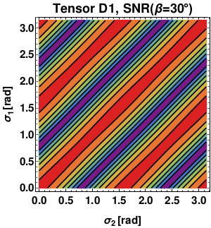

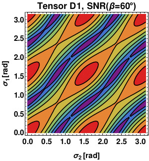

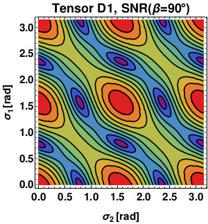

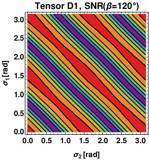

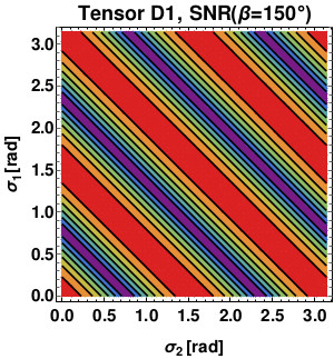

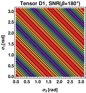

All these cases present the common Type II optimal configuration, although the more the separation angle approaches , the more we get some narrow bands of ideal orientations which maximize the SNR. This can be understood considering the limit , thus the ORF in Eq.(46) is only affected by the sum of the two detector orientations (and not anymore by their difference) and both Type I and Type II configurations are optimal, along with all configurations lying on the straight lines. We should mention that analogous results can be found for B1. Since the optimal Type II configuration is shared among all possible distances between the two detectors, in the left panel of Fig.10 we show the expected SNR as a function of using B1 and D1 configurations for a direct comparison.


If only tensor modes are present, we find that D1 is the best configuration for every angular separation considered between the pair, with the latter approximately doubling its sensitivity to the SGWB with respect to B1. Note how in both scenarios the SNR rapidly decreases for relatively small distances between the two detectors until it reaches a minimum value, then slowly starts to increase again for higher relative distances between members of the pair. This behavior is analogous to the one discussed in Nishizawa et al. (2009) for the second-generation of ground-based interferometers. It is also possible to understand how the detectable SGWB energy density varies as a function of the spatial distance between the two interferometers, as shown in the right panel of Fig.10. Here we assumed again a frequency independent energy density spectrum for tensor modes in Eq.(55), though this time we fix the value of the SNR (which we use to claim detection) and set yrs. Both expected SNR and detectable energy density values are listed in Tab.1 for both B1 and D1 configurations using different fixed angular separations: in terms of detectable energy density, we generally find that the ETA-CE pair sensitivity to a SGWB made of tensor modes only is approximately improved by a factor with respect to current limits (see recent limits provided by Abbott et al. (2021)).
| SNRT | ||||
|---|---|---|---|---|
| B1 | D1 | B1 | D1 | |

We now focus on two ET detectors (e.g. ETA and ETB) at our disposal and we consider the corresponding ORF shown in Fig.11. Note how due to the two detectors relative small distance ( km), the ORF starts to oscillate at higher GW frequencies. Moreover, given the frequency range to which ET is expected to be sensitive (- Hz), we can assume = = with and being one among ETA, ETB and ETC. In real situations, whenever Hz we no longer are in the low frequency limit and we should consider how ORFs are affected by detector transfer functions: however, as a first approximation, neglecting the latter does not have a significant impact on the final results. This time we have two possible configurations: either both interferometer sensitivity curves are represented by ET-B, or both interferometers are in the xylophone configuration with sensitivity curves given by ET-D. We refer to the first ad second configuration as “BB” and “DD” respectively. Similarly to what we previously did, we assume a frequency-independent energy density spectrum for the tensor modes and we show the results for both expected SNR ( and yrs) and detectable energy density (SNR and yrs) in Tab.2.
| SNRT | ||
|---|---|---|
| BB | ||
| DD |
If both interferometers are in a xylophone configuration, we find that the pair sensitivity to the SGWB is approximately doubled with respect to the BB one and results for the detectable energy density can be further compared to the ones obtained for the ETA-CE pair. Moreover, considering Tab.1 and Tab.2, configurations DD and D1 with provide very similar results, while taking higher angular separations between ET and CE, the DD layout is always more sensitive to the SGWB with respect to D1. Therefore, if only tensor modes are present, in first approximation we find that an ET pair is generally slightly more sensitive to the SGWB with respect to a ET-CE pair 888For a more detailed treatment one needs to consider some ET technical specifications in order to account for the presence of transfer functions Schilling (1997)..
V SGWB made of Tensor and Vector or Scalar polarization modes
In this section we want to extend the previous results obtained for a SGWB involving only tensor modes to a SGWB made of both tensor and one other class of extra polarization modes , with = or . Once again, our results refer to the third-generation of ground-based interferometers. In realistic situations, we need to consider the possibility where we dispose of two ET interferometers along with CE: we mentioned that ET comes with three detectors, though we shall see in this section a first example showing how only two of them can be taken to work independently for our considerations (see Philippoz et al. (2018) for a detailed discussion on this matter). Moreover, after we understand how to remove tensor modes contributions to the SNR for the SGWB Omiya and Seto (2020), we will separately focus on a SGWB made of tensor along with vector or scalar polarization modes to show some differences and similarities between the two cases. Considering ET and CE, we finally present our forecasts for vector and scalar polarization modes detectable energy density contributions to the SGWB.
V.1 Tensor modes deletion
Let us consider a SGWB made of both tensor and extra -polarization modes (i.e. tensor and vector or scalar polarization modes): drawing from Omiya and Seto (2020) and considering a generic triad of detectors , and , the SNR expression for the extra polarization modes is derived in Appendix A and it is given by
| SNRX | (57) |
As a consistency check, note that if only tensor modes exist, then and the integrand numerator collapses to zero, making the SNR null for every GW-frequency range considered. Indeed this cancellation technique allow us to reduce to zero the tensor modes contribution to the SNR defined for the SGWB, thus singling out the additional -polarization modes. In order to study the latter, we also require the integrand numerator to be different from zero, meaning that the condition
needs to be satisfied. While working with ET and CE, we shall see that this happens only for finite frequency ranges whose values are much smaller than both the ET and CE characteristic frequency , meaning we can safely work in the low-frequency limit. Note how the interferometer plays the role of a “dominant” detector, since it affects all ORFs in Eq.(57). We will show how its choice (whether it is identified with one ET interferometer or CE) finally influences the optimal configurations and SNR formula. Additionally, once we specify the nature of the “dominant” detector, we find that Eq.(57) can be written in a more compact way, therefore we now show our results for different possible scenarios while having at our disposal three ET interferometers and CE.
V.1.1 “Dominant” detector represented by the Cosmic Explorer
We first consider the case where the “dominant” detector is given by CE, while detectors and are ET interferometers (e.g. ETA and ETB). The SNR for X-extra polarization modes can be written as
| (58) |
where we have introduced the effective overlap reduction function (EORF) for X-polarization modes
| (59) |
When EORFs are null, reflecting the fact that and share approximately the same value in this limit Allen and Romano (1999). Recalling Eqs.(46), (49), (52), let be the orientation of the CE bisector and the orientation of the ETB one: due to ET topology the orientation of the ETA interferometer bisector will always be . Finally, let be the angular separation between ET and CE. Under these assumptions, for general X-polarization modes we get
Clearly, the CE orientation filters the sensitivity to GWs: indeed whenever , meaning , the signal is null for every frequency range. If , then and it is straightforward to show that the EORF numerator is zero, while if , then and the EORF is zero again: these two angular separation values correspond to a null signal, meaning that in order to detect X-polarization modes the detector plane normal vector cannot be the same or the opposite for both ET and CE.
V.1.2 “Dominant” detector represented by the Einstein Telescope
Let us now consider the case where ETB is the “dominant” detector, with the second and third interferometers being ETA and CE respectively, therefore we further assume (as we shall see, we are safe to work in the low-frequency limit). The SNR is given by
where we have introduced the noise-affected EORF for X-polarization modes
| (61) |
with a frequency-dependent function defined as
Noise-affected EORFs tell us we only need to worry about ORFs relative to the single ETB-CE detector pair, therefore we shall see how the SNR is then maximized by one among Type I or Type II layouts introduced in Eq.(56), depending on the angular separation between ET and CE.
V.1.3 Three Einstein Telescope interferometers
Let us now consider the case where we have three ET detectors at our disposal. Due to ET triangular topology, once we select tensor, vector or scalar polarization modes, the respective ORFs (shown in Fig.11) for each possible pair involving detectors ETA, ETB and ETC are the same. More explicitly, this means that = = for = , and , thus the SNR numerator in Eq.(57) is always equal to zero. Unfortunately, this means that only two ET interferometers may be taken to work independently while working with a network of detectors Philippoz et al. (2018), thus it is mandatory to consider CE (or another ground-based detector) in order to distinguish between different polarization modes.
V.2 SGWB made of Tensor and X-polarization modes
We now consider a SGWB made of tensor and X-polarization modes, with = or (see e.g. Beltran Jimenez and Maroto (2009); Kimura et al. (2017); Heisenberg et al. (2017) and Fujii and Maeda (2003); Alonso et al. (2017); Heisenberg et al. (2018) for vector-tensor and scalar-tensor theories of gravity respectively). Given two possible scenarios, we begin by considering CE as the “dominant” detector and we assume a frequency-independent energy density spectrum for both tensor and vector polarization modes. The expected value for the SNR can be found using Eq.(58) once we set both the observation time yrs and a reference value = for the detectable energy density. Let now be the orientation of the CE bisector and the orientation of the ETB one: similarly to what we did for a SGWB made of tensor modes, in Figs.12 (vector modes) and 13 (scalar modes) we show the results for the expected SNR using the configuration D1 for several fixed values of while leaving the orientation of both detectors free to vary.
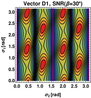

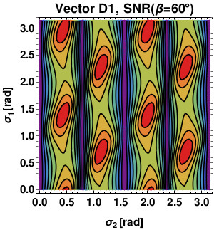

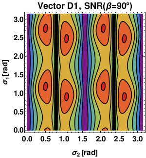

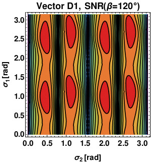

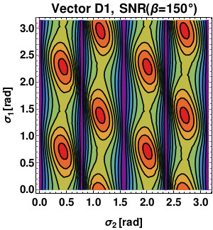

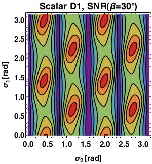

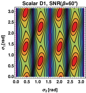

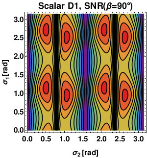

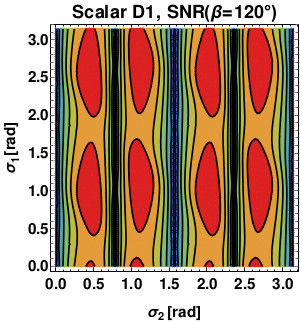

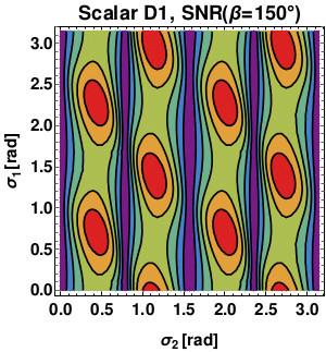

As previously anticipated while discussing EORFs, there are four “bands” separated by vertical straight lines of SNR null values corresponding to the case where . We find that the CE optimal orientation is approximately the same for every value of for both vector and scalar polarization modes, though this is no longer true for ET and we do not have same optimal orientations shared among all angular separations between ET and CE. Considering Figs.12 and 13, a set (given ORFs and EORFs periodicity) of ideal values for and which maximize the SNR for each value of can be extrapolated: we further show the corresponding optimal EORFs for vector and scalar polarization modes in Fig.14. Note how these functions filter the frequency range where the isolation of extra polarization modes becomes possible. The peaks appearing come from the almost simultaneous zeros of the ORFs in the denominator of . Finally, in Tabs.3 and 4 we show results for both expected SNR ( and = yrs) and detectable energy density (SNR and yrs) using configurations B1 and D1 with optimal orientations for ET and CE. We find that the D1 configuration is generally the best one, which in particular for = and = approximately doubles and triples its sensitivity to vector and scalar polarization modes in terms of detectable energy density with respect to the B1 configuration, while for larger angles, the process reverses, leading to completely worse expected forecasts (i.e. for ). An exception is made by small spatial distances between the pair () where B1 results the best layout (note this will not be the case if final locations for ET and CE are Europe and North America respectively).


| SNRV | ||||
|---|---|---|---|---|
| B1 | D1 | B1 | D1 | |
| SNRS | ||||
|---|---|---|---|---|
| B1 | D1 | B1 | D1 | |
We now retrace these steps considering the interferometer ETB as the “dominant” detector: once again, we begin with the expected SNR ( and = yrs). Keeping and as the ETB and CE bisector orientations respectively, our results are shown in Figs.15 (vector modes) and 16 (scalar modes).
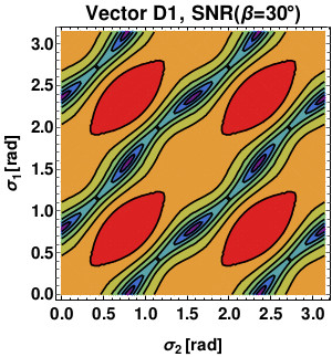

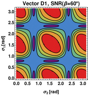

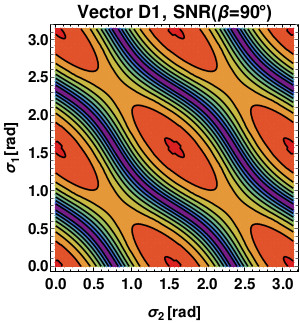

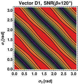

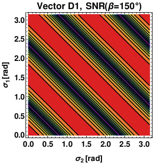

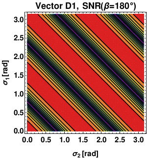

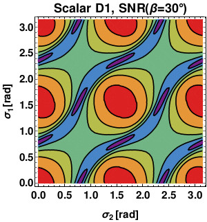

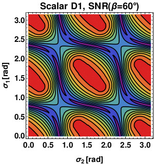

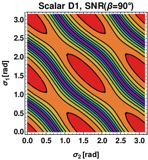

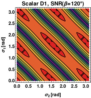

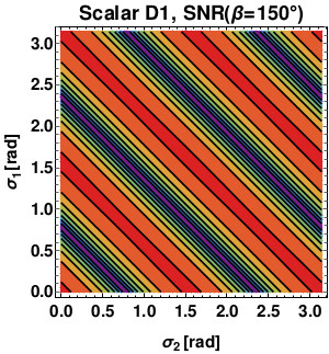

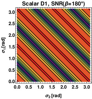

Interestingly, recalling we only need to focus on ORFs related to the ETB-CE detector pair (see Eq.(61)), we find we can describe all possible scenarios in terms of optimal Type I and Type II layouts introduced in Eq.(56): results for different values of the angular separation between ET and CE are shown in Tabs.5 (vector modes) and 6 (scalar modes) using the D1 configuration.
| Angular separation | Optimal config. |
|---|---|
| Vector D1 | |
| Type I | |
| Type II | |
| Type II | |
| Type II | |
| mod | |
| mod |
| Angular separation | Optimal configuration |
|---|---|
| Scalar D1 | |
| Type II | |
| Type II | |
| Type II | |
| Type II | |
| mod | |
| mod |
Additionally, the corresponding optimal noise-affected EORFs are shown in Fig.17, with the peaks appearing shortly after Hz coming from the spikes in the ET-D sensitivity curve, as shown in the left panel of Fig.6. In Tabs.7 and 8 we list the results for both expected SNR ( and yrs) and detectable energy density (SNR and yrs) using configurations B1 and D1 with optimal orientations for ET and CE. With the exception of small spatial distances between the pair ( = ) where B1 gives better forecasts, once again, we find that the D1 configuration is the best one, where the network greatly improves its sensitivity to both vector and scalar polarization modes in the SGWB. Moreover, better forecasts for the expected SNR and detectable energy density are related to larger angular separations between the two detectors.


| SNRV | ||||
|---|---|---|---|---|
| B1 | D1 | B1 | D1 | |
| SNRS | ||||
|---|---|---|---|---|
| B1 | D1 | B1 | D1 | |
Finally, comparing results in Tabs.3 and 4, and in Tabs.7 and 8 we find how the network is slightly more sensitive to scalar modes instead of vector modes, independently from the value of the angular variable . Despite the arbitrary choice of the “dominant” detector, we showed that forecasts relative to both the expected SNR and detectable energy density for a SGWB made of tensor and -polarization modes (with or ) can be directly compared to results obtained for the space-based LISA-Taiji network in Omiya and Seto (2020).
VI SGWB made of Tensor, Vector and Scalar modes
In the most general scenario a SGWB might be made of tensor, vector and scalar polarization modes at the same time. In literature, it is a well-known result that in order to separate these polarization modes we need to consider detector networks involving at least three interferometers Nishizawa et al. (2009). Then, the SNR expression for tensor, vector and scalar polarization modes separately can be derived (see Appendix A) and we have
| (62) |
where , with =, , , and are given by Eqs.(80), (81), (82) and (91) respectively. Clearly, tensor, vector and scalar polarization modes are allowed to be algebraically isolated as long as the condition is satisfied: we anticipate that for an ET-CE network this is true only for finite frequency ranges with relative values much smaller than both ET and CE characteristic frequency . Therefore, we are safe to work in the low-frequency limit once again and we proceed to discuss our results for ET and CE. In particular, in order to better understand when the isolation of tensor, vector and scalar polarization modes is allowed, in the following we investigate two different cases: first, we consider the network involving CE along with two ET interferometers (e.g. ETA and ETB), then we move on to the network involving three ET interferometers (i.e. ETA, ETB and ETC). We finally present our forecasts for tensor, vector and scalar polarization modes detectable energy density contributions to the SGWB and we compare them to the ones recently provided by Abbott et al. (2021) for second-generation ground-based interferometers.
VI.1 ETA-ETB-CE network
Let us first consider the case where interferometers , and are given by ETA, ETB and CE respectively: this might be the first third-generation collaboration among ground-based detectors to be fully exploited in the following two decades, therefore we now start our analysis of the network. Let be the orientation of the CE bisector, the orientation of the ETB one and the one relative to ETA. Additionally, since we are working in the low-frequency limit, we further assume (see Fig.11). For a fixed value of , it is straightforward to show that
Note that this result does not depend on ET orientation due to its triangular topology, while the CE orientation filters the sensitivity to GWs: indeed we find that whenever , then and the signal is null for tensor, vector and scalar modes, no matter what the separation angle is. When , then and the signal is null, while if , then and the signal is again null: this means that the detector plane orthogonal direction cannot be the same or opposite for both detectors, similarly to a SGWB made of tensor and -polarization modes (with or ), with CE being the “dominant” detector. We now consider Eq.(62) in order to compute the expected SNR for an energy density reference value , while assuming a frequency independent energy density spectrum for tensor, vector and scalar polarization modes. In Fig.18, Fig.19 and Fig.20 we show the results for the expected SNR using the D1 configuration for several fixed values of while leaving the orientation of both detectors free to vary.
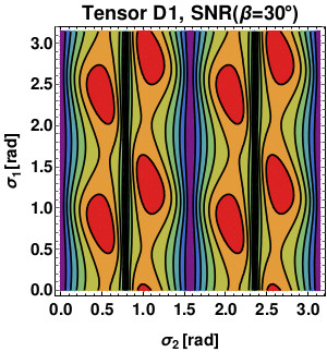

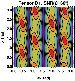

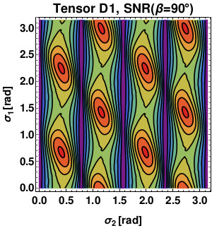

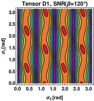

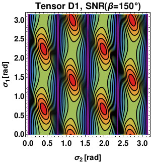

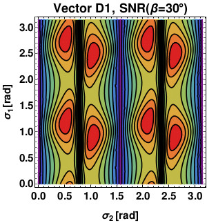

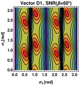

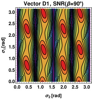

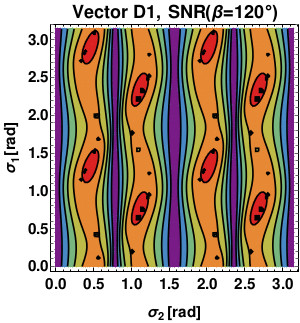

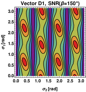

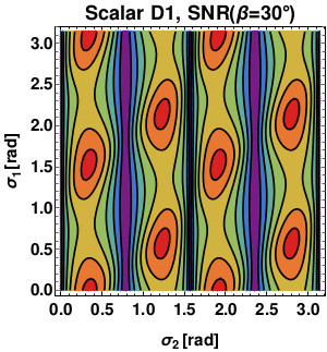

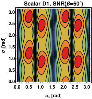

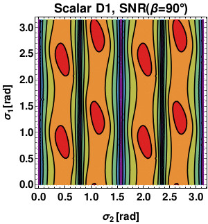

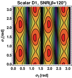

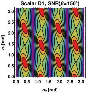

We immediately recognize four “bands” separated by vertical straight lines of null SNR values, corresponding to the case where . With the exception of small angular separations (), from Figs.18, 19 and 20 we clearly see that for tensor, vector and scalar polarization modes the CE optimal orientation is once again approximately the same for each value of . On the other hand, ET optimal orientations are not greatly shared among different polarization mode (i.e. they are not approximately the same for tensor, vector and scalar polarization modes), meaning that if we choose bisector orientations in order to maximize SNRT, we lose some sensitivity in terms of scalar and vector modes or the other way around. Indeed, this behavior affects the corresponding optimal functions, which are shown in Fig.21: given the angular separation, these look similar to each other being only proportional to the CE orientation and ignoring the ET one as we discussed. This means that the isolation of tensor, vector and scalar polarization modes is allowed in almost identical frequency ranges.


We show in Tabs.9, 10 and 11 results for both expected SNR ( and yrs) and detectable energy density (SNR and yrs) for tensor, vector and scalar modes respectively using configurations B1 and D1 with optimal orientations for ET and CE.
| SNRT | ||||
|---|---|---|---|---|
| B1 | D1 | B1 | D1 | |
| SNRV | ||||
|---|---|---|---|---|
| B1 | D1 | B1 | D1 | |
| SNRS | ||||
|---|---|---|---|---|
| B1 | D1 | B1 | D1 | |
In terms of tensor modes, we find that the D1 configuration is the best one, with the usual exception of small spatial distances between the pair ( = ) where B1 gives better forecasts. On the other hand, we find that B1 can be equally or more sensitive to vector modes in the SGWB with respect to D1. Finally, in terms of scalar modes, the best configuration depends on the angular separation between ET and CE: we have B1 more sensitive to scalar modes for and , while the D1 arrangement gives better forecasts for all other suggested values. For each polarization class and configuration, as the angular separation increases, the expected SNR and detectable energy density first reach a maximum and minimum value respectively, then, the processes reverses, leading to worse expected forecasts (indeed in Fig.21 we see that , and the expected SNR gets smaller). We now compare results in Tabs.9, 10 and 11 to energy density upper limits for tensor and non-GR provided by Abbott et al. (2021). If we are allowed to choose the proper angular separation between ET and CE, we find that a network built with third-generation ground-based interferometers approximately improves its sensitivity to tensor and extra polarization modes in the SGWB by a factor in terms of corresponding detectable energy density contributions to the background energy density.
VI.2 ETA-ETB-ETC network
Let us consider Fig.1 once again: ET triangular configuration provides three ground-based interferometers. We mentioned that in order to separate tensor, vector and scalar polarization modes we first need to consider Eq.(91), in particular it must be at least for a finite frequency range where the polarization modes are allowed to be separated. Moreover, we also stated that we can assume for =, and in the low-frequency limit. This configuration clearly presents a problem, since no matter what angular separation or frequency range we are considering, we always get , meaning the SNR is null. This issue only arises because of ET triangular topology 999As shown in detail in Philippoz et al. (2018), small perturbations of the simmetry of ET are not sufficient to allow the isolation of tensor, vector and scalar polarization modes using the three interferometers provided by the observatory. and it is not related to incoming GW properties: even when we exit the low-frequency limit, as long as ORFs are the same for each pair, ET alone is not able to distinguish different polarization modes in terms of their energy density contributions to the SGWB.
VII Cosmic Explorer replacing LIGO observatories
In sections V and VI we discussed that only two ET interferometers can be taken to work independently (see also e.g. Philippoz et al. (2018)) along with CE in order to successfully isolate tensor, vector and scalar polarization modes energy density contributions to the SGWB. In this section, we extend our previous results to the particular case where we dispose of a network made of one ET interferometer and two CE-like interferometers replacing the two LIGO observatories in North America both in location and orientation: we refer to these detectors as “CEL” for the Livingston site and “CEH” for the Hanford site. Moreover, we assume ET to be located either in Italy (Sardinia site) or at the border region between the Netherlands, Belgium and Germany (Euregio Meuse-Rhine site), while we leave its orientation (which we measure in a counterclokcwise manner with respect to the great circumference connecting CEL and ET) free to vary. Let us begin by considering a SGWB made of tensor and -polarization modes, with = or . In order to remove tensor modes contributions to the SNR for the SGWB, we can safely recover Eq.(57) (since there are no colocated interferometers we assume detector noises to be uncorrelated): we know all detector locations along with CEH and CEL angular orientations, which means that the SNR can be seen as a function of the only ET orientation. In Fig.22 we show the expected SNRX ( and yrs) we computed assuming a frequency-independent energy density spectrum for both tensor and -polarization modes and considering the two possible ET sites and layouts (described by ET-B and ET-D sensitivity curves as shown in the left panel of Fig.6) along with the Stage 1 CE.


We remind the reader that Fig.22 (and Fig.23 below) was obtained while performing some numerical integrations: due to some limits on the precision and accuracy of numerical calculations, some of the related subfigures show small distortions. However, the latter do not change the physics of the problem and the considerations we made in this paper. Moreover, each SNR curve refers to a different “dominant” detector: we find that better forecasts for the expected SNR are mostly given by “dominants” CEH and CEL depending on the value of for all possible scenarios. Additionally, the D1 configuration generally improves the network sensitivity to the SGWB with respect to B1. This is true in particular for the Sardinia site, where the sensitivity to non-GR polarization modes is approximately doubled. Note also that peaks appearing in both SNRV and SNRS while considering the D1 configuration are higher for the Sardinia site, meaning that the latter could provide better detectable energy density values for vector or scalar polarization modes with respect to the Euregio Meuse-Rhine site: indeed SNRX is of order unity, therefore if we e.g. set SNR to claim detection, yrs and we compute , the latter can be directly compared to results listed in Tabs.3, 7, 4, 8 where two ET interferometers and one CE were considered, reconfirming the network gain in sensitivity to extra polarization modes with respect to second-generation ground-based interferometers. Let us now move on to the most general case where tensor, vector and scalar polarization modes are present at the same time: we further consider Eq.(62) and we investigate what is the network sensitivity to GWs of different polarizations. In Fig.23 we show the expected SNRM, with , , and , ( and yrs) which we again computed assuming a frequency-independent energy density spectrum for tensor, vector and scalar polarization modes and considering the two possible B1 and D1 layouts.


Once we choose the site for ET, we find that there are no significant changes for tensor and scalar modes while switching between configurations B1 and D1. An exception is made for SNRV curves, where corresponding peaks are slightly higher while considering ET in its xylophone configuration. Additionally, we also find that the network is approximately twice more sensitive to tensor and scalar polarization modes with respect to vector modes. Moreover, SNRM peaks approximately correspond to the same value of for , and , meaning that if we optimally choose the ET orientation, we get close-to-ideal SNRM values for tensor, vector and scalar polarization modes at the same time. Although this applies to both ET sites, the best choice would be the Euregio Meuse-Rhine location, which would slightly improve the network sensitivity (SNR peaks) to all polarization modes. This can be better understood with a concrete example, therefore we choose for the Sardinia site and for the Euregio Meuse-Rhine site. We further set SNR and we compute the detectable energy density for both cases: results are shown in Tab.12 and, once again, can be directly compared to some of the optimal ones listed in Tabs.9, 10 and 11: indeed, with respect to second-generation detectors Abbott et al. (2021), we find once again that a third-generation network of ground-based interferometers approximately improves its sensitivity to tensor and extra polarization modes in the SGWB by a factor .
| Sardinia site | Eur. Meuse-Rhine site | |
|---|---|---|
VIII Detector responses to high gw frequencies
As long as one is working in the low-frequency limit, it is a well known result in literature that a single GW interferometer presents the same angular response to scalar-breathing and scalar-longitudinal polarization modes Romano and Cornish (2017), represented by the corresponding APFs which only differ for a constant factor, as shown in Eqs.(11), (12), (21) and (22). We also mentioned that this prevents both ET and CE (and more generally all ground-based detectors) from distinguishing between the two scalar modes. However, the third-generation of ground-based interferometers is expected to be sensitive to GW frequencies equal to or even higher than the relative detector characteristic frequency (i.e. ET optimistically will be sensitive to frequencies in the - Hz range, though its characteristic frequency is Hz, while CE sensitivity curves CE1 and CE2 are defined between - Hz, though its characteristic frequency is Hz). Therefore, focusing on ET and CE, in this section we discuss how breathing and longitudinal APFs behave once we exit the low-frequency limit in order to study detector angular responses to scalar polarization modes considering higher GW frequencies. In the most general case, we dispose of an interferometer with opening angle , with and we define relative unit vectors directed along each detector arm as
When we approach and/or surpass , APFs are still given by the tensor contraction in Eq.(5), though the detector tensor is now frequency dependent because of the presence of the so-called transfer functions Romano and Cornish (2017) defined for each detector arm, which are different depending on the nature of the interferometer considered (e.g. Michelson or Fabry-Pérot interferometer Schilling (1997)). Given a general interferometer with relative transfer functions , with , we get
where
Moreover, we are now able to compute breathing and longitudinal APFs while exiting the low-frequency limit, we get
| (64) |
| (65) |
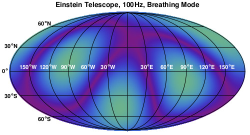
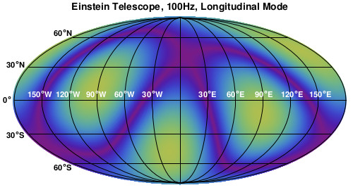
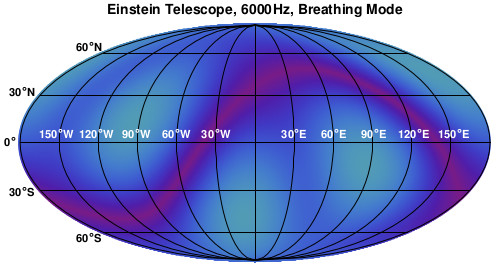
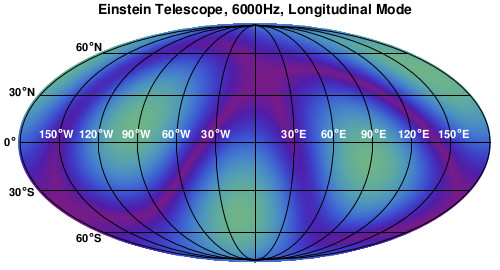
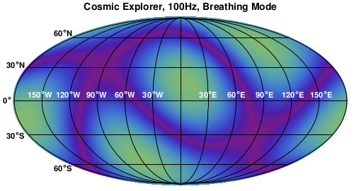
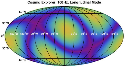
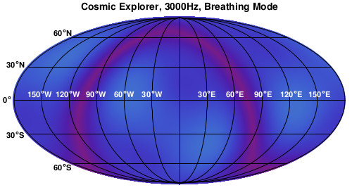
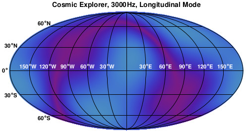
As a consistency check, if we assume , then (considering normalized transfer functions) and if or , APFs once again reduce to Eqs.(21) and (22) or Eqs.(11) and (12) respectively. If we take a closer look at Eqs.(64) and (65), we see that the opening angle only affects the degenerate terms, meaning that the choice of does not break the scalar modes degeneracy, no matter which frequency range we are considering. However, if GW frequencies approach or surpass the characteristic frequency , we find that the scalar modes degeneracy is always broken by the factor and ground-based interferometers are able to distinguish between breathing and longitudinal polarization modes given their brand-new and different angular responses (see also Liu et al. (2020a); Liang et al. (2019) for recent work on this topic with upcoming space-based interferometers). Note that this is no longer allowed while considering second-generation ground-based interferometers (e.g. LIGO, Virgo and KAGRA): due to their shorter arm lengths and worse sensitivities (with respect to ET and CE), these detectors are not sensitive to GW frequencies higher than their corresponding characteristic values . We now consider an Earth-based coordinate and we assume a single ET interferometer (e.g. ETA) to be located in Sardinia and CE to replace the LIGO Livingston observatory both in location and orientation; moreover, we assume both detectors to be simple Michelson interferometers. We show in Fig.24 plots of both detector angular responses to breathing and longitudinal polarization modes for the two cases where the low-frequency limit can or cannot be taken to be valid. We visibly recover what Eqs.(64) and (65) were suggesting: in terms of scalar modes, for sufficiently low GW frequencies the same detector is equally sensitive to different angular directions in the sky. However, when GW frequencies are higher than , detector responses to breathing and longitudinal modes behave very differently.








IX Conclusions
In this paper, we discussed in detail the detectability of non-GR polarization modes of a SGWB with third-generation ground-based detectors Einstein Telescope and Cosmic Explorer considering different possible orientations and locations on the Earth. The existence of such polarization modes is predicted by many alternative theories of gravitation and constraining these extra polarization modes would provide a useful tool to test such theoretical models (and at the same time a further test of GR), while their detection would be an inequivocable smoking gun of new physics beyond the standard model of GR.
We first investigated the ET network joint angular response to vector and scalar polarization modes. At the level of sky coverage, we found that in terms of extra polarization modes more isotropic joint responses are obtained with respect to a single L-shaped interferometer, though ET is still insensitive to GWs coming from the orthogonal direction to the detector plane, with respect to which joint responses present cylindrical symmetry.
We then considered possible detector networks with ET and CE in order to algebraically isolate Nishizawa et al. (2009); Omiya and Seto (2020) tensor, vector and scalar energy density contributions to the SGWB, where we assumed frequency-independent energy density spectra (see Eq.(35)). It is worth mentioning that ET alone is not able to exploit its three interferometers to achieve this result: this limitation comes from ET triangular topology Philippoz et al. (2018), therefore it is mandatory to also consider correlation with CE. We found results for several angular separations on Earth between ET and CE while using ideal orientations and considering five years of observation for each case. If only tensor modes are present, a SGWB with could be detected by the ETA-CE detector pair in its D1 configuration, with ETA in its xylophone layout along with CE in Stage 1 (see Fig.6). On the other hand, two ET interferometers (e.g. ETA-ETB) in their xylophone configuration could give equal or better forecasts with respect to the ETA-CE pair with an angular separation of . In the presence of additional -polarization modes (with being one between vector or scalar modes) and despite the arbitrary choice of the “dominant” detector (see Eq.(A.2)), we found that by properly choosing the angular separation between ET and CE and their relative orientations the ETA-ETB-CE network in its D1 configuration could detect energy density contributions to the SGWB of order for both vector and scalar polarization modes. Finally, when tensor, vector and scalar polarization modes are present at the same time, we have that the ETA-ETB-CE detector network loses some of its sensitivity to different polarization modes: using its D1 configuration, the network could isolate and detect tensor, vector and scalar modes energy density contributions to the SGWB of , for , and . Interestingly, in terms of vector modes, the same network in its B1 configuration would provide slightly better detection limits (in this case ET detectors are seen as single interferometers sensitive to the whole expected ET frequency range along with the Stage 1 CE).
Next, we investigated the possibility of having two CE-like interferometers replacing the LIGO observatories in North America both in location and orientation. We also considered the two proposed locations for ET, which are given by the Sardinia island site in Italy and the Euregio Meuse-Rhine site in northern Europe; we then focused on the CEL-CEH-ETA network in order to isolate and detect non-GR polarization modes in the SGWB. If only tensor and -polarization modes (with or ) are present and choosing an optimal orientation for ETA, we found that the best configuration for the network is obtained with ET in a xylophone configuration located in the Sardinia site, with detection limits for the detectable energy density given by for both vector and scalar polarization modes. If tensor, vector and scalar modes are present at the same time, the network sensitivity to all polarization modes (in particular to tensor and scalar modes) is slightly improved by assuming ET in the Euregio Meuse-Rhine site, while there are no significant changes in forecasts moving from the B1 to the D1 configuration and the other way around. Choosing the proper orientation for ETA, detection limits are approximately for tensor and scalar modes and for vector modes.
In order to sum up our results, we can state that in terms of energy density contributions for tensor, vector and scalar polarization modes to the SGWB total energy density, all considered networks involving only ET and CE interferometers approximately improve their sensitivity to the SGWB by a factor with respect to current forecasts provided by Abbott et al. (2021); in particular, while considering valid locations and orientations for CE and ET, along with the latter in its proposed xylophone configuration, the corresponding network could detect energy density contributions to the SGWB in the range , with , and . We can further state that these detection limits can be directly compared to those found in Omiya and Seto (2020) using a network of space-based detectors (i.e. LISA and Taiji).
We finally investigated the possibility of breaking the scalar modes degeneracy with the new generation of ground-based interferometers. While considering GW frequencies , with being the interferometer arm, detector angular responses to breathing and longitudinal polarization modes differ for a constant factor, making scalar modes indistinguishable for the interferometer. However, both ET and CE are expected to be sensitive to GWs with frequencies larger than their corresponding characteristic : moving to this higher frequency-regime, we showed how different and new frequency-dependent angular responses can be obtained and how the degeneracy between scalar modes can be broken considering the new generation of ground-based interferometers (similarly to what is done in Liu et al. (2020a); Liang et al. (2019) with the new generation of space-based interferometers).
The analysis performed in this paper can open the possibility to test many scalar-tensor and vector-tensor theories using third-generation interferometers, constraining some modified gravity parameters Bartolo et al. (2021). We leave such an analysis for future works.
Acknowledgments
L.A. would like to express his gratitude to A. Nishizawa for his useful comments given at the beginning of this project during his visit to the Department of Physics and Astronomy “Galileo Galilei”, University of Padova.
A.R. acknowledges funding from Italian Ministry of Education, University and Research (MIUR) through the “Dipartimenti di
eccellenza” project Science of the Universe.
N.B. acknowledges partial financial support by ASI Grant No. 2016-24- H.0 and 2016-24-H.1-2018.
The work was supported by the International Helmholtz-Weizmann Research School for Multimessenger Astronomy, largely funded through the Initiative and Networking Fund of the Helmholtz Association.
Appendix A Signal to Noise ratio
Correlation analysis represents a useful and well-developed tool to detect a SGWB Allen and Romano (1999); Romano and Cornish (2017). Here, we wish to retrace the steps needed to find the proper SNR expression for tensor and, when present in the SGWB, vector and scalar polarization modes. We draw heavily from Nishizawa et al. (2009); Omiya and Seto (2020), to which we refer the reader for more details.
A.1 Tensor modes
When only tensor modes are present, we begin by considering the output of two detectors and and we further introduce the cross-correlation signal
| (66) |
where is the so-called filter function used in the end to maximize the SNR and we introduced
with the observation time; coincides with the Dirac delta function in the limit , which we safely assume to be valid considering the sensitivity of ground-based detectors to GW-frequency ranges and an observation time of a few years. Taking the ensemble average of Eq.(40) and also considering Eqs.(66) and (39), we get
The next step is to compute the corresponding variance in order to get the noise term: assuming GW-signals much smaller than the detector noise and recalling Eq.(38) we get
| (68) | |||||
We can express both Eqs.(LABEL:eq:a.2) and (68) in a simpler and compact way by introducing the following inner product
thus we have
| (70) |
| (71) |
We can finally choose the proper expression for the filter function in order to maximize the SNR, which is given by
In the end, we get the SNR expression for the SGWB in the presence of tensor modes only
| SNRT | ||||
A.2 Tensor and X-polarization modes
We now extend the previous results to a SGWB made of tensor and -polarization modes, where stands for vector or scalar: since we need (at least) three interferometers to work with, let us consider the following data combination
where , and denote the three detectors at our disposal. Analogously to what we did in Eq.(66), for the X-polarization modes we now define the cross correlation signal and its ensemble average as
| (73) |
where we used Eqs.(39) and (40) and we defined
and the relative variance
Given the data combination , in the last equality of Eq.(LABEL:eq:a12.0), terms cancel out and we are left with the only contribution of -extra polarization modes. We further introduce the following inner product in order to express Eqs.(LABEL:eq:a12.0) and (LABEL:eq:a12.01) in a more compact way
thus both the signal and noise terms can be written as
and
| (78) |
The expression of the filter function that maximizes the SNR this time is given by
therefore we end up with the following SNR expression in the presence of a SGWB made of tensor and X-extra polarization modes
| SNRX | (79) |
A.3 Tensor, Vector and Scalar polarization modes
We finally consider a SGWB made of tensor, vector and scalar polarization modes in the general scenario where we dispose of three independent interferometers (e.g. ETA, ETB and CE): we introduce the following data combination defined for tensor, vector and scalar polarization modes as
where , with , , and , and , are frequency-dependent coefficients. The idea is similar to what we did in the previous subsection: we need to find an expression for the frequency-dependent coefficients in order to remove the contribution of undesired polarization modes to the SNR for the SGWB. The simplest frequency-dependent coefficients needed to isolate one specific polarization class are given by
-
•
Tensor modes
(80) -
•
Vector modes
(81) -
•
Scalar modes
(82)
We now recall Eqs.(39) and (40) in order to define the cross-correlation combination for each polarization mode (we already consider the ensemble average)
which represents the signal and we further introduce the corresponding variance
| (84) | |||||
We still need to find an expression for the filter function, therefore we introduce
| (85) | |||||
| (86) | |||||
Moreover, we can define the inner product
| (87) |
so that we can express both signal and noise as
| (88) | |||
| (89) |
In order to maximize the SNR, we now need to find the proper expression for the filter function. The latter is given by
In the end, we finally get the SNR expression for tensor, vector and scalar polarization modes separately
| SNRM | ||||
where
| (91) |
References
- Abbott et al. (2016a) B. P. Abbott, R. Abbott, T. Abbott, M. Abernathy, F. Acernese, K. Ackley, C. Adams, T. Adams, P. Addesso, R. Adhikari, et al., Physical review letters 116, 061102 (2016a).
- Abbott et al. (2016b) B. P. Abbott, R. Abbott, T. Abbott, M. Abernathy, F. Acernese, K. Ackley, C. Adams, T. Adams, P. Addesso, R. Adhikari, et al., arXiv preprint arXiv:1602.03841 (2016b).
- Abbott et al. (2016c) B. P. Abbott, R. Abbott, T. Abbott, M. Abernathy, F. Acernese, K. Ackley, C. Adams, T. Adams, P. Addesso, R. Adhikari, et al., Physical review letters 116, 241103 (2016c).
- Scientific et al. (2017) L. Scientific, B. Abbott, R. Abbott, T. Abbott, F. Acernese, K. Ackley, C. Adams, T. Adams, P. Addesso, R. Adhikari, et al., Physical Review Letters 118, 221101 (2017).
- Abbott et al. (2017a) B. P. Abbott, R. Abbott, T. Abbott, F. Acernese, K. Ackley, C. Adams, T. Adams, P. Addesso, R. Adhikari, V. Adya, et al., The Astrophysical Journal Letters 851, L35 (2017a).
- Abbott et al. (2017b) B. P. Abbott, R. Abbott, T. Abbott, F. Acernese, K. Ackley, C. Adams, T. Adams, P. Addesso, R. X. Adhikari, V. Adya, et al., Physical review letters 119, 141101 (2017b).
- Abbott et al. (2017c) B. P. Abbott, R. Abbott, T. Abbott, F. Acernese, K. Ackley, C. Adams, T. Adams, P. Addesso, R. Adhikari, V. Adya, et al., Physical Review Letters 119, 161101 (2017c).
- Abbott et al. (2020a) R. Abbott, T. Abbott, S. Abraham, F. Acernese, K. Ackley, C. Adams, R. Adhikari, V. Adya, C. Affeldt, M. Agathos, et al., Physical review letters 125, 101102 (2020a).
- Brans and Dicke (1961a) C. Brans and R. H. Dicke, Physical review 124, 925 (1961a).
- Sotiriou and Faraoni (2010) T. P. Sotiriou and V. Faraoni, Reviews of Modern Physics 82, 451 (2010).
- De Felice and Tsujikawa (2010a) A. De Felice and S. Tsujikawa, Living Reviews in Relativity 13, 1 (2010a).
- Hellings and Nordtvedt Jr (1973) R. W. Hellings and K. Nordtvedt Jr, Physical Review D 7, 3593 (1973).
- Will and Nordtvedt Jr (1972) C. M. Will and K. Nordtvedt Jr, The Astrophysical Journal 177, 757 (1972).
- De Felice and Tsujikawa (2010b) A. De Felice and S. Tsujikawa, Living Rev. Rel. 13, 3 (2010b), arXiv:1002.4928 [gr-qc] .
- Capozziello and De Laurentis (2011) S. Capozziello and M. De Laurentis, Phys. Rept. 509, 167 (2011), arXiv:1108.6266 [gr-qc] .
- Clifton et al. (2012) T. Clifton, P. G. Ferreira, A. Padilla, and C. Skordis, Phys. Rept. 513, 1 (2012), arXiv:1106.2476 [astro-ph.CO] .
- Heisenberg (2018) L. Heisenberg, JCAP 10, 054 (2018), arXiv:1801.01523 [gr-qc] .
- Heisenberg et al. (2018) L. Heisenberg, R. Kase, and S. Tsujikawa, Phys. Rev. D 98, 024038 (2018), arXiv:1805.01066 [gr-qc] .
- Will (2014) C. M. Will, Living reviews in relativity 17, 1 (2014).
- de Rham et al. (2017) C. de Rham, J. T. Deskins, A. J. Tolley, and S.-Y. Zhou, Rev. Mod. Phys. 89, 025004 (2017), arXiv:1606.08462 [astro-ph.CO] .
- Will (2018) C. M. Will, Theory and experiment in gravitational physics (Cambridge university press, 2018).
- Ezquiaga and Zumalacárregui (2018) J. M. Ezquiaga and M. Zumalacárregui, Front. Astron. Space Sci. 5, 44 (2018), arXiv:1807.09241 [astro-ph.CO] .
- Maggiore (2008) M. Maggiore, Gravitational waves: Volume 1: Theory and experiments, Vol. 1 (Oxford university press, 2008).
- Maggiore (2018) M. Maggiore, Gravitational Waves: Volume 2: Astrophysics and Cosmology (Oxford University Press, 2018).
- Allen and Romano (1999) B. Allen and J. D. Romano, Physical Review D 59, 102001 (1999).
- Note (1) See also recent constraints on the polarization of GWs from single events Abbott et al. (2019, 2017b, 2020b).
- Romano and Cornish (2017) J. D. Romano and N. J. Cornish, Living reviews in relativity 20, 2 (2017).
- Nishizawa et al. (2009) A. Nishizawa, A. Taruya, K. Hayama, S. Kawamura, and M.-a. Sakagami, Physical Review D 79, 082002 (2009).
- Abbott et al. (2021) R. Abbott, T. Abbott, S. Abraham, F. Acernese, K. Ackley, A. Adams, C. Adams, R. Adhikari, V. Adya, C. Affeldt, et al., arXiv preprint arXiv:2101.12130 (2021).
- Barsotti et al. (2018) L. Barsotti, L. McCuller, M. Evans, and P. Fritschel, LIGO Document: LIGO-T1800042 (2018).
- Unnikrishnan (2013) C. Unnikrishnan, International Journal of Modern Physics D 22, 1341010 (2013).
- Arzoumanian et al. (2016) Z. Arzoumanian, A. Brazier, S. Burke-Spolaor, S. J. Chamberlin, S. Chatterjee, B. Christy, J. M. Cordes, N. J. Cornish, K. Crowter, P. B. Demorest, et al., The Astrophysical Journal 821, 13 (2016).
- Chen et al. (2021) Z.-C. Chen, C. Yuan, and Q.-G. Huang, arXiv preprint arXiv:2101.06869 (2021).
- Arzoumanian et al. (2020) Z. Arzoumanian, P. T. Baker, H. Blumer, B. Bécsy, A. Brazier, P. R. Brook, S. Burke-Spolaor, S. Chatterjee, S. Chen, J. M. Cordes, et al., The Astrophysical Journal Letters 905, L34 (2020).
- Note (2) Http://www.et-gw.eu/.
- Note (3) Https://cosmicexplorer.org/.
- Amaro-Seoane et al. (2017) P. Amaro-Seoane, H. Audley, S. Babak, J. Baker, E. Barausse, P. Bender, E. Berti, P. Binetruy, M. Born, D. Bortoluzzi, et al., arXiv preprint arXiv:1702.00786 (2017).
- Ando et al. (2010) M. Ando, S. Kawamura, N. Seto, S. Sato, T. Nakamura, K. Tsubono, T. Takashima, I. Funaki, K. Numata, N. Kanda, et al., Classical and Quantum Gravity 27, 084010 (2010).
- Kawamura et al. (2011) S. Kawamura, M. Ando, N. Seto, S. Sato, T. Nakamura, K. Tsubono, N. Kanda, T. Tanaka, J. Yokoyama, I. Funaki, et al., Classical and Quantum Gravity 28, 094011 (2011).
- Luo et al. (2016) J. Luo, L.-S. Chen, H.-Z. Duan, Y.-G. Gong, S. Hu, J. Ji, Q. Liu, J. Mei, V. Milyukov, M. Sazhin, et al., Classical and Quantum Gravity 33, 035010 (2016).
- Hu and Wu (2017) W.-R. Hu and Y.-L. Wu, “The taiji program in space for gravitational wave physics and the nature of gravity,” (2017).
- Note (4) See e.g. Barish et al. (2020) for recent work on “midband” detectors which are expected to close the frequency gap between space-based and ground-based interferometers.
- Bartolo et al. (2016) N. Bartolo et al., JCAP 12, 026 (2016), arXiv:1610.06481 [astro-ph.CO] .
- Caprini et al. (2019) C. Caprini, D. G. Figueroa, R. Flauger, G. Nardini, M. Peloso, M. Pieroni, A. Ricciardone, and G. Tasinato, JCAP 11, 017 (2019), arXiv:1906.09244 [astro-ph.CO] .
- Baker et al. (2019) J. Baker et al., (2019), arXiv:1908.11410 [astro-ph.HE] .
- Maggiore et al. (2020) M. Maggiore, C. Van Den Broeck, N. Bartolo, E. Belgacem, D. Bertacca, M. A. Bizouard, M. Branchesi, S. Clesse, S. Foffa, J. García-Bellido, et al., Journal of Cosmology and Astroparticle Physics 2020, 050 (2020).
- Barausse et al. (2020) E. Barausse et al., Gen. Rel. Grav. 52, 81 (2020), arXiv:2001.09793 [gr-qc] .
- Contaldi et al. (2020) C. R. Contaldi, M. Pieroni, A. I. Renzini, G. Cusin, N. Karnesis, M. Peloso, A. Ricciardone, and G. Tasinato, Phys. Rev. D 102, 043502 (2020), arXiv:2006.03313 [astro-ph.CO] .
- Orlando et al. (2021) G. Orlando, M. Pieroni, and A. Ricciardone, JCAP 03, 069 (2021), arXiv:2011.07059 [astro-ph.CO] .
- Sathyaprakash et al. (2019) B. Sathyaprakash, E. Belgacem, D. Bertacca, C. Caprini, G. Cusin, Y. Dirian, X. Fan, D. Figueroa, S. Foffa, E. Hall, et al., arXiv preprint arXiv:1903.09260 (2019).
- Flauger et al. (2021) R. Flauger, N. Karnesis, G. Nardini, M. Pieroni, A. Ricciardone, and J. Torrado, JCAP 01, 059 (2021), arXiv:2009.11845 [astro-ph.CO] .
- Dall’Armi et al. (2021) L. V. Dall’Armi, A. Ricciardone, N. Bartolo, D. Bertacca, and S. Matarrese, Phys. Rev. D 103, 023522 (2021), arXiv:2007.01215 [astro-ph.CO] .
- Omiya and Seto (2020) H. Omiya and N. Seto, Physical Review D 102, 084053 (2020).
- Note (5) Outside the SGWB context, see Takeda et al. (2019) for recent work on ET and CE to test extra polarization modes from compact binary mergers.
- Regimbau et al. (2012) T. Regimbau, T. Dent, W. Del Pozzo, S. Giampanis, T. G. Li, C. Robinson, C. Van Den Broeck, D. Meacher, C. Rodriguez, B. S. Sathyaprakash, et al., Physical Review D 86, 122001 (2012).
- Liu et al. (2020a) C. Liu, W.-H. Ruan, and Z.-K. Guo, Physical Review D 102, 124050 (2020a).
- Liang et al. (2019) D. Liang, Y. Gong, A. J. Weinstein, C. Zhang, C. Zhang, et al., Physical Review D 99, 104027 (2019).
- Liu et al. (2020b) X. Liu, V. F. He, T. M. Mikulski, D. Palenova, C. E. Williams, J. Creighton, and J. D. Tasson, arXiv preprint arXiv:2005.03121 (2020b).
- Schilling (1997) R. Schilling, Classical and Quantum Gravity 14, 1513 (1997).
- Cutler (1998) C. Cutler, Physical Review D 57, 7089 (1998).
- Schutz (2011) B. F. Schutz, Classical and Quantum Gravity 28, 125023 (2011).
- Punturo et al. (2010) M. Punturo, M. Abernathy, F. Acernese, B. Allen, N. Andersson, K. Arun, F. Barone, B. Barr, M. Barsuglia, M. Beker, et al., Classical and Quantum Gravity 27, 194002 (2010).
- Reitze et al. (2019a) D. Reitze, R. X. Adhikari, S. Ballmer, B. Barish, L. Barsotti, G. Billingsley, D. A. Brown, Y. Chen, D. Coyne, R. Eisenstein, et al., arXiv preprint arXiv:1907.04833 (2019a).
- Note (6) For some recent works about non-Gaussianities and anisotropies of the SGWB, see e.g. Bartolo et al. (2018, 2019, 2020a, 2020b); Dall’Armi et al. (2021).
- Note (7) Techniques to identify noise correlation terms relative to a pair of co-located detectors have been developed e.g. for the two LIGO Hanford interferometers Fotopoulos et al. (2008) and could be generalized to ET.
- Hild et al. (2008) S. Hild, S. Chelkowski, and A. Freise, arXiv preprint arXiv:0810.0604 (2008).
- Hild et al. (2009) S. Hild, S. Chelkowski, A. Freise, J. Franc, N. Morgado, R. Flaminio, and R. DeSalvo, Classical and Quantum Gravity 27, 015003 (2009).
- Hild et al. (2011) S. Hild, M. Abernathy, F. Acernese, P. Amaro-Seoane, N. Andersson, K. Arun, F. Barone, B. Barr, M. Barsuglia, M. Beker, et al., Classical and Quantum Gravity 28, 094013 (2011).
- Reitze et al. (2019b) D. Reitze, R. Abbott, C. Adams, R. Adhikari, N. Aggarwal, S. Anand, A. Ananyeva, S. Anderson, S. Appert, K. Arai, et al., arXiv preprint arXiv:1903.04615 (2019b).
- Note (8) For a more detailed treatment one needs to consider some ET technical specifications in order to account for the presence of transfer functions Schilling (1997).
- Philippoz et al. (2018) L. Philippoz, A. Boîtier, and P. Jetzer, Physical review D 98, 044025 (2018).
- Beltran Jimenez and Maroto (2009) J. Beltran Jimenez and A. L. Maroto, JCAP 02, 025 (2009), arXiv:0811.0784 [astro-ph] .
- Kimura et al. (2017) R. Kimura, A. Naruko, and D. Yoshida, JCAP 01, 002 (2017), arXiv:1608.07066 [gr-qc] .
- Heisenberg et al. (2017) L. Heisenberg, R. Kase, M. Minamitsuji, and S. Tsujikawa, JCAP 08, 024 (2017), arXiv:1706.05115 [gr-qc] .
- Fujii and Maeda (2003) Y. Fujii and K.-i. Maeda, The Scalar-Tensor Theory of Gravitation, Cambridge Monographs on Mathematical Physics (Cambridge University Press, 2003).
- Alonso et al. (2017) D. Alonso, E. Bellini, P. G. Ferreira, and M. Zumalacárregui, Phys. Rev. D 95, 063502 (2017), arXiv:1610.09290 [astro-ph.CO] .
- Note (9) As shown in detail in Philippoz et al. (2018), small perturbations of the simmetry of ET are not sufficient to allow the isolation of tensor, vector and scalar polarization modes using the three interferometers provided by the observatory.
- Bartolo et al. (2021) N. Bartolo, L. Caloni, G. Orlando, and A. Ricciardone, JCAP 03, 073 (2021), arXiv:2008.01715 [astro-ph.CO] .
- Bartolo et al. (2019) N. Bartolo, D. Bertacca, S. Matarrese, M. Peloso, A. Ricciardone, A. Riotto, and G. Tasinato, Phys. Rev. D 100, 121501 (2019), arXiv:1908.00527 [astro-ph.CO] .
- Abbott et al. (2017d) B. P. Abbott et al. (LIGO Scientific, Virgo, Fermi-GBM, INTEGRAL), Astrophys. J. Lett. 848, L13 (2017d), arXiv:1710.05834 [astro-ph.HE] .
- Abbott et al. (2019) B. P. Abbott, R. Abbott, T. Abbott, F. Acernese, K. Ackley, C. Adams, T. Adams, P. Addesso, R. X. Adhikari, V. B. Adya, et al., Physical review letters 123, 011102 (2019).
- Abbott et al. (2020b) R. Abbott, T. Abbott, S. Abraham, F. Acernese, K. Ackley, A. Adams, C. Adams, R. Adhikari, V. Adya, C. Affeldt, et al., arXiv preprint arXiv:2010.14529 (2020b).
- Takeda et al. (2019) H. Takeda, A. Nishizawa, K. Nagano, Y. Michimura, K. Komori, M. Ando, and K. Hayama, Physical Review D 100, 042001 (2019).
- Fotopoulos et al. (2008) N. V. Fotopoulos, L. S. Collaboration, et al., in Journal of Physics: Conference Series, Vol. 122 (IOP Publishing, 2008) p. 012032.
- Barish et al. (2020) B. C. Barish, S. Bird, and Y. Cui, arXiv preprint arXiv:2012.07874 (2020).
- Bartolo et al. (2018) N. Bartolo, V. Domcke, D. G. Figueroa, J. Garcia-Bellido, M. Peloso, M. Pieroni, A. Ricciardone, M. Sakellariadou, L. Sorbo, and G. Tasinato, Journal of Cosmology and Astroparticle Physics 2018, 034 (2018).
- Bartolo et al. (2020a) N. Bartolo, D. Bertacca, S. Matarrese, M. Peloso, A. Ricciardone, A. Riotto, and G. Tasinato, Physical Review D 102, 023527 (2020a).
- Bartolo et al. (2020b) N. Bartolo, D. Bertacca, V. De Luca, G. Franciolini, S. Matarrese, M. Peloso, A. Ricciardone, A. Riotto, and G. Tasinato, Journal of Cosmology and Astroparticle Physics 2020, 028 (2020b).
- Brans and Dicke (1961b) C. Brans and R. H. Dicke, Phys. Rev. 124, 925 (1961b).
- Berti et al. (2015) E. Berti et al., Class. Quant. Grav. 32, 243001 (2015), arXiv:1501.07274 [gr-qc] .