Impact of a microfluidic jet onto a pendant droplet
Abstract
High speed microfluidic jets can be generated by a thermocavitation process: from the evaporation of the liquid inside a microfluidic channel, a rapidly expanding bubble is formed and generates a jet through a flow focusing effect. Here, we study the impact and traversing of such jets on a pendant liquid droplet. Upon impact, an expanding cavity is created, and, above a critical impact velocity, the jet traverses the entire droplet. We predict the critical traversing velocity (i) from a simple energy balance and (ii) by comparing the Young-Laplace and dynamic pressures in the cavity that is created during impact. We contrast the model predictions against experiments, in which we vary the liquid properties of the pendant droplet and find good agreement. In addition, we asses how surfactants and viscoelastic effects influence the critical impact velocity. Our results are relevant for the study of needle-free injections, where jets of similar velocities and dimensions are being used. Given the simplicity of our system we can systematically vary the target properties and unravel their effect on the impact dynamics, a true challenge when injecting into real skin.
1 Introduction
The impact of a solid or liquid object into a deep liquid pool generates a cavity with dynamics first described by Worthington (1908). Since then, research has focused on many topics, including the critical energy necessary for air entrainment into the pool, the collapse of the formed cavity, and the subsequent formation of Worthington jets (Oguz et al., 1995; Lee et al., 1997; Zhu et al., 2000; Lorenceau et al., 2004; Aristoff & Bush, 2009; Truscott et al., 2014). However, the projectiles studied usually have sizes in the range of 0.2 to 5 mm and an impact speed range of 1 to 10 m/s, and the pool is usually orders of magnitude larger than the projectile. In these cases, hydrostatic pressure has been found a major driver for the collapse and retraction of the cavity made on the liquid pool (Oguz et al., 1995). In contrast, in this paper we study (for the first time) the impact of micrometer-sized jets onto a compact liquid object, namely a droplets of mm. The jets travel at speeds of 20 m/s, and the hydrostatic pressure can be neglected due to the size of the created cavity.
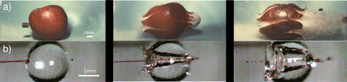
Since, the dynamics of the aforementioned events take place in a few miliseconds, high-speed imaging is required to observe the phenomena. High-speed imaging was pioneered by scientists like Harold E. Edgerton, with his strobe-flash photography technique (Edgerton, 1931). One of his most famous sequences of pictures is that of a 0.22 inch caliber bullet traversing an apple at m/s (figure 1a). In this sequence, the apple is opaque, but, what if we could replace the target with a transparent object, i.e., a liquid apple? This is precisely the case when we target a droplet with a liquid microjet. As shown in figure 1, the aesthetic of a high-speed jet traversing a liquid droplet and Edgerton’s pictures is strikingly similar. The difference being that, with a translucent liquid, we can observe the impact dynamics inside the droplet, and besides producing impressive images, high-speed imaging facilitates the description of the fast phenomena, such as providing the projectile speed and the target deformation.
Our aim in this paper is to unravel the physics that govern the impact of liquid water jets on a pendant droplet of liquids with different properties. Ultimately, this knowledge targets at increasing our understanding of needle-free injection in skin. Needle-based injections are among the most common procedures in modern medicine, but pain and phobia affect patience compliance (Hamilton, 1995; Sokolowski et al., 2010). Needle-free injections with liquid jets have been proposed to solve some of these issues, with jet velocities as high as 100 m/s —and volumes ranging from 10 nL to 1 mL (Prausnitz et al., 2004; Hogan et al., 2015; Mohizin & Kim, 2018).
More recently, the potential of jets with 1-25 nL –micro-jets– and superficial penetration in skin has been demonstrated (Kiyama et al., 2019a; Cu et al., 2019; Oyarte Gálvez et al., 2020; Krizek et al., 2020). However, for micro-jet injectors to become a reality, understanding the impact and penetration dynamics of the liquid into real tissue in real time is crucial (Mercuri & Fernandez Rivas, 2021). Systematic studies aimed at quantifying the effect of skin properties during an injection are challenging, because the geometry, variability and opacity of the skin difficult optical access. In the current experiments, however, we can precisely vary and control the droplet properties and study the dynamics of jet penetration using droplets as skin surrogate.
The paper is structured as follows. The experimental procedure is outlined in §2. In §3 we present two models to predict the critical jet velocity for traversing a droplet: In §3.1 we use an energy balance between the kinetic energy of the jet and the surface energy of the droplet. In §3.2, we employ the two-dimensional Rayleigh equation to obtain the cavity shape and combine it with the Young-Laplace equation to predict its collapse. Next, the model prediction is contrasted against experimental results in §4.1. Additionally, in §4.2 and §4.3 we present experimental results on the cavity advancing and retracting velocities with some observations on what occurs after the cavity collapse.
2 Experimental Method
High-speed jets were generated from a thermocavitation process and directed to impact a pendant droplet of different liquids with varying properties. Thermocavitation refers to the phenomena where a liquid is vaporised locally by means of a focused laser, leading to bubble nucleation (Rastopov & Sukhodolsky, 1991; Padilla-Martínez et al., 2014). The expansion of the nucleated bubble can be controlled on a microfluidic chip to generate a jet through a flow-focusing effect (Rodríguez et al., 2017; Oyarte Gálvez et al., 2020). These jets may reach speeds in the order of 100 m/s, which, is enough to pierce the skin, and has potential for transdermal delivery of a liquid, particularly needle-free injections (Cu et al., 2019; Oyarte Gálvez et al., 2019). However, in the experiments described here, we restrict the jet velocity to the range of 8 - 35 m/s, which is sufficient for a jet to traverse droplets of the liquids studied. Additionally, the diameter of the liquid jet was in the range of = 50 - 120 m. Both and were controlled by varying the laser spot size and power.
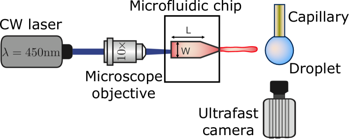
The experimental setup is shown in figure 2. A Borofloat glass microfluidic chip fabricated under cleanroom conditions is filled with a water solution containing a red dye (Direct Red 81, CAS No. 2610-11-9) at 0.5 wt. . The red dye enhances the laser energy absorption and facilitate the bubble nucleation. The microfluidic device has a tapered channel with an angle degrees to avoid swirling of the jet (Oyarte Gálvez et al., 2020), nozzle diameter 120 m, channel length m and width m. The thermocavitation bubble is created by focusing a continuous wave laser diode (Roithner LaserTechnik, wavelength nm and nominal power of 3.5 W), at the microchannel with a 10x microscope objective. The liquids used were water, ethanol, aqueous solutions of glycerol, Triton x-100 and sodium-bis(2-ethylhexyl)sulfosuccinate (Aerosol OT) at different concentrations and polyethylene-oxide of varied molecular weight (PEO). Liquid droplets were created by holding a capillary tube with outer diameter of 360 m, controlling the volume with a precision glass syringe and a syringe pump (Harvard PHD 22/2000). All chemical additives were bought from Sigma-Aldrich. The properties of the Newtonian and non-Newtonian liquids used are reported in table 1. The surface tension of all the liquids was measured with the Pendent Drop ImageJ plugin (Daerr & Mogne, 2016), and their shear viscosity with an Anton Paar MCR 502 rheometer.
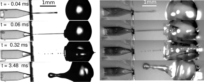
The processes of bubble generation, jet ejection and impact on the liquid droplet were recorded with a Photron Fastcam SAX coupled with a 2x microscope objective. A typical experiment duration was ms and the camera resolution was set to pixels2 at a sample rate of k frames per second with an exposure time of s. Typical images obtained from the experiments are shown in figure 3, where one observes how a water droplet is pierced by the liquid jet produced from the microchip on the left, using shadowgraph imaging (left) and direct lighting (right). Experiments were carried out with a typical shadowgraph configuration, and we switched to a front light illumination system to observe the cavity dynamics. In the front illumination system a white background was placed to enhance image contrast and increase the light reaching the camera sensor. Image analysis to extract the jet diameter, impact velocity and cavity dynamics was performed with a custom generated MATLAB script. The shadowgraph imaging benefits from more light reaching the sensor, and thus a smaller camera exposure time can be used, leading to a better jet definition. However, extracting information from the expanding cavity is impossible. In contrast, with front light imaging we can extract the information from the expanding cavity, but the jet is not as well defined as with shadowgraphy.
| Fluid | (mPa s) | (mN/m) | (kg/m3) | (ms) |
|---|---|---|---|---|
| Ethanol | 1.04 | 26.3 | 789 | - |
| Water | 1.0 | 72.1 | 998 | - |
| Aqueous Glycerol 25 v | 2.4 | 69.7 | 1071 | - |
| Aqueous Glycerol 50 v | 8.4 | 67.6 | 1142 | - |
| Aqueous Glycerol 70 v | 28.7 | 66.1 | 1193 | - |
| Aqueous Glycerol 78 v | 43.6 | 65.2 | 1212 | - |
| Triton 0.2 CMC | 1.0 | 43.9 | 998 | - |
| Triton 1 CMC | 1.0 | 30.8 | 998 | - |
| Triton 3 CMC | 1.0 | 32.5 | 998 | - |
| Aerosol OT 1 wt. (AOT 1) | 1.0 | 23.4 | 998 | - |
| Aerosol OT 0.1 wt. (AOT 0.1) | 1.0 | 24.1 | 998 | - |
| Water red dye 0.5 wt. | 0.91 | 47.0 | 1000 | - |
| PEO 100k 0.1 wt | 1.03 | 63.2 | 996 | 0.006 |
| PEO 100k 1 wt | 2.43 | 62.9 | 995 | 0.047 |
| PEO 100k 10 wt | 50.8 | 62.5 | 1001 | 0.333 |
| PEO 600k 0.1 wt | 1.56 | 63.1 | 996 | 0.307 |
| PEO 600k 1 wt | 21.7 | 62.9 | 998 | 1.317 |
3 Critical jet velocity
In this section, we predict the critical velocity needed for a jet to traverse a droplet using two different approaches, (i) by using a simple energy balance and (ii) by comparing the Young-Laplace and dynamic pressures in the cavity that is created during impact. In §3.1, we start from an energy analysis of Edgerton’s experiment of a bullet traversing an apple and subsequently transfer the argument to the droplet case of our current study. With this example we introduce the concept of kinetic energy of the projectile and the resistance of the target to being traversed. Moreover, we deduce the critical velocity of the jet by doing an energy balance between the kinetic energy of the jet and the surface energy of the droplet. Additionally, in §3.2, we use the Rayleigh’s two dimensional equation to predict the shape of the cavity and predict its collapse with the Young-Laplace equation, thus finding the jet critical traversing velocity.
3.1 Energy balance between the jet kinetic energy and the droplet surface energy
In his lecture titled How to Make Applesauce at MIT, Edgerton presented his famous series of pictures of bullets traversing apples presented in figure 1a. This set of images illustrated the traversing process, but did not reflect on the energy of the bullet or the energy of the apple. What would it take the apple to stop the bullet? Or equivalently, what would be the necessary speed for the bullet to get trapped and embeded inside the apple?
In this section, we will answer these questions by using an energy balance between the kinetic energy of a bullet , where is the mass of the bullet, and the toughness of an apple , which we define as its ability to absorb energy by elastoplastic deformation without fracturing. Hence, by doing the energy balance, the critical velocity for the bullet to penetrate the apple may be written as
| (1) |
The mass of a .22 caliber bullet is g and the apple toughness is J (Grotte et al., 2001). Therefore, m/s, which is at least one order of magnitude smaller than the typical velocities reached by .22 caliber bullets, m/s. Consequently, it is understandable that the apple is traversed by the bullet in Edgerton’s photographs.
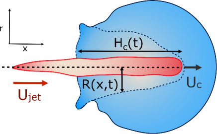
For our liquid jet, the kinetic energy is , with and the density and length of the jet respectively, and the resisting force of the droplet is dominated by its surface energy. For the critical conditions where the jet traverses the droplet, the jet kinetic energy transforms into the surface energy of the cavity generated at impact. For simplicity, assuming that the cavity geometry is cylindrical, the cavity surface energy is , with the droplet surface tension and the cavity diameter. Here, is constrained by and as shown in figures 3 and 4, . Also, since the velocity of the tip of the cavity is approximately half the jet velocity , the total length of the jet would not contribute to the traversing process but only a part of it, namely (Bouwhuis et al., 2016). Using this limiting value , the jet critical velocity for droplet traversing is
| (2) |
Defining the relevant Weber number of the jet as , and substituting Eq. 2 we find the critical minimal Weber number needed to traverse the droplet
| (3) |
Substituting typical values of a jet impacting a water droplet in our experiments ( kg/m3, m 2 mm and 0.07 mN/m), we obtain m/s or .
Now, we have all the ingredients to do a scaling comparison between a bullet traversing an apple and a jet traversing a droplet. Taking the values of and from the experiments in figure 1a) and 1b (which are well above the critical value for penetration in both cases) and the target toughness (toughness for an apple and surface energy for a droplet), we get that . Therefore, the relative energies involved in both processes are of the same order of magnitude, indicating that the traversing phenomena in both cases share more than aesthetic similarities. Nevertheless, after impact, the fractured apple does not possess the restoring force a liquid droplet has, namely, the surface tension. This is the cause of the much appreciated fact that we did not have to deal with substantial amounts of debris after our experiments.
3.2 Comparison between the Young-Laplace and dynamic pressures of the cavity
Considering the mass of a cylindrical liquid jet with radius and length falling into a pool of the same liquid, air is entrained in the pool at sufficiently energetic impacts, i.e., and (Oguz et al., 1995). Additionally, the cavity dynamics and the air entrainment depend on the aspect ratio of the jet. The limiting cases are , corresponding to the impact of a continuous jet, and , where the case of a droplet impact into a liquid pool is recovered (Oguz et al., 1995; Kiger & Duncan, 2012). For the former case, the apex of the cavity advances with a velocity , therefore, the depth of the cavity can be estimated as (Oguz et al., 1995; Bouwhuis et al., 2016; Speirs et al., 2018b).
In the cavity formation of a droplet impacting a liquid surface, the process is mainly inertial during the first instants, with surface tension becoming important at the moment near the maximum depth of the cavity (Bouwhuis et al., 2016). Additionally, Deng et al. (2007) showed that viscous dissipation accounts for of the initial kinetic energy loss of a water droplet of mm impacting a liquid pool. Therefore, assuming that the cavity shape is slender and the process is inertia dominated, i.e., neglecting viscous dissipation, we can apply the two-dimensional Rayleigh equation in cylindrical coordinates to predict the cavity shape (Bergmann et al., 2006; Eggers et al., 2007),
| (4) |
where , is the radius of the cavity and is the position of the cavity on the horizontal direction and is an external length scale (see figure 4). Following the argument of Bouwhuis et al. (2016), during the first instants of the cavity formation, inertia dominates and the dynamics are determined by . Solving this equation we get that , where and , and the approximate cavity profile is (Bouwhuis et al., 2016),
| (5) |
The time at which surface tension can influence the cavity walls can be predicted by comparing the dynamic pressure of the radially expanding cavity and the Young-Laplace pressure based on the azimuthal curvature of the cavity,
| (6) |
where is the cavity radius at the jet impact point . Taking the cavity profile from Eq. 5, we get , and (Bouwhuis et al., 2016). Therefore,
| (7) |
and
| (8) |
The condition for the jet to traverse the droplet is that . Using that and Eqs. 7 and 8, the critical impact velocity for the jet to traverse the droplet is
| (9) |
and
| (10) |
For a jet impacting a water droplet, mm, N/m, m and kg/m3, we obtain that the critical velocity needed to traverse the droplet is m/s, which is larger than obtained from equation (2). Similarly, which is about twice as large as for equation (3).
While the results in equations (3) and (10) are of the same order of magnitude, their dependence on the ratio is different, namely linear in equation (3) whereas in equation (10), there is a square root dependence. This discrepancy arises from the difference in the geometric shape of the generated cavity that was assumed in the two approaches, resulting in a different surface energy. Indeed, a very simple cylindrical geometry was assumed during the energy balance method. In contrast, deriving equation (10) using the Rayleigh equation, leads to a more rigorous description of the cavity shape. Therefore, we consider the latter model to be more accurate and in the following section will compare our experimental data to equation (10).
4 Results and discussion
In this section we will describe our experiments on the traversing of the jet through the droplet and compare them to the above criterion. Furthermore, we modify the criterion to include the concept of dynamic surface tension of the droplet in the case of surfactant covered droplets. After that we will briefly discuss the cavity dynamics, focusing on the motion of the apex of the cavity inside the droplet. Finally, we comment on our observations for droplets containing surfactants and non-Newtonian liquids.
4.1 Critical velocity for traversing
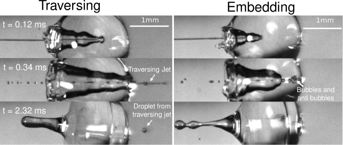
We start the discussion of our experimental results by making a qualitative description of the observed phenomena. Figure 5 shows an image sequence from two typical experiments. Upon impact of the jet onto the droplet, a cavity is generated inside the droplet. The cavity diameter and depth increase with time and its growth rate is dependent on the impact conditions (Speirs et al., 2018b). At a velocity above a critical value, the jet traverses the droplet completely, as is observed in the left panel of figure 5. In contrast, if the jet velocity is not sufficiently large, the jet gets embedded in the droplet and bubbles and anti-bubbles may be created, as in the right panel of 5 (see also Song et al. (2020)). Finally, and irrespective of which of these two scenarios applies a rebound Worthington jet is generated.
Now we move on to verifying the validity of the traversing criterion expressed in the critical Weber number obtained in equation (10), for varying droplet properties. To compare the experimental data and the model presented in section §3.2, we use the ratio between the experimentally obtained Weber number and the expected critical Weber number from equation (10). Additionally, for the droplets that contain surfactants we need to take into account that, when the jet impacts the droplet and the cavity starts to form, new surface area is created and the surface density of the surfactant decreases. Therefore, the surface tension locally increases from the surface tension measured at equilibrium and the cavity presents a dynamic surface tension (Speirs et al., 2018a). Consequently, in the surfactant case we re-define the Weber number as , i.e., using in its definition, and divide it by the critical value leading to,
| (11) |
Clearly in the above equation, for the droplets that do not contain sufactants (the glycerol solutions, water and ethanol) we just insert . For Triton X-100 solutions, the dynamic surface tension can be assessed by the diffusion scale , which is the time for the surface tension to decrease from the surface tension of water to the equilibrium surface tension (Bobylev et al., 2019). The diffusion scale depends on the diffusion coefficient of the surfactant (for Triton X-100 m2/s), the maximum surface concentration of surfactant ( mol/m2), the Langmuir equilibrium adsorption constant ( m3/mol) and its volume concentration (Bobylev et al., 2019; Ferri & Stebe, 2000). For the 3 CMC Triton X-100 solution (the largest concentration used in these experiments), ms, while the characteristic timescale of the traversing/embedding process is ms, i.e. two orders of magnitude smaller. Hence, the dynamic surface tension does not have enough time to reach the measured equilibrium surface tension. Therefore, we do not expect the equilibrium surface tension of Triton X-100 solutions to be relevant in the jet traversing process. Consequently, we assume the dynamic surface tension of the Triton X-100 solutions to be that of water.
In contrast, AOT being a vesicle surfactant can migrate faster than micelle surfactants such as Triton X-100 (Song et al., 2017; Wang et al., 2019). In addition, it was shown that at ms the dynamic surface tension of an AOT solution at 1 wt. can decrease to a value of mN/m (Song et al., 2017). Therefore, we assume that for the AOT solutions is mN/m. We should note however, that AOT dynamics are more complex than those of Triton, and characterisation using a single time scale is an oversimplification.
Figure 5 shows the experimental results of traversing and embedding impact cases as a phase diagram, where on the vertical axis we plot the ratio of the (dynamic) Weber number and the expected critical Weber number , using equation (11) such that based upon the model described in §3.2 we would expect a transition at . On the horizontal axis we separate the liquid properties of the droplet by plotting the Ohnesorge number, defined as , which is the ratio between viscous forces to inertial and surface tension forces, and has the advantage that is a material property, i.e. it is independent of the dynamics. Open symbols in figure 5 represent cases where the jet was observed to traverse the droplet, (as in figure 5 left) and solid symbols represent the situation where the jet does not traverse the droplet, i.e., becomes embedded as seen in figure 5 right.
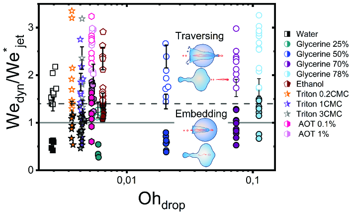
From figure 6, we observe that most of the open symbols lie above the same approximate value and conversely for closed symbols. The exception is formed by the data for the AOT solutions, where it is possible that is underestimated as mN/m, and in fact lies closer to the surface tension of water mN/m. An accurate measurement of the dynamic surface tension in such timescales is challenging (Speirs et al., 2018a; Alvarez et al., 2010) and is out of the scope of this work. However, as demonstrated by our results, the dynamic surface tension can play a pronounced role for different dynamic conditions. Therefore, we can safely conclude that the impact process is initially dominated by inertia and that surface tension is the major opposing force.
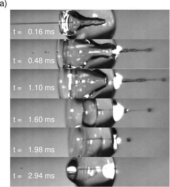
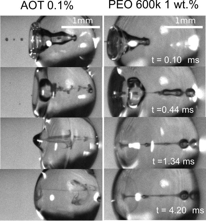
Turning to the viscoelastic droplets, figure 7b shows data for the jet traversing and embedding impact cases for droplets consisting of the PEO solutions. In this figure, we plot against the Deborah number defined as , where is the relaxation time of the polymer (see table 1) and is the capillary timescale. We use this definition of the Deborah number to our PEO solution droplets, as we expect to observe deviations from the Newtonian behaviour when becomes comparable to the scale at which surface tension starts to influence the cavity dynamics, i.e. at the capillary time scale . In figure 7, open and closed symbols again represent traversing and embedding cases respectively and half-filled symbols denote an intermediate state between traversing and embedding, which we call pearling. During pearling, the jet travels a distance larger than after impact and thus protrudes from the droplet, but due to the viscoelastic properties of the liquid gets sucked back into the droplet, as visualised in the experimental snapshots of figure 7a.
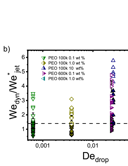
From figure 7b that the traversing and embedding process for the PEO solutions with , is similar for Newtonian liquids, leading to the same threshold value , showing that the viscoelastic effects are weak. However, as increases, i.e., when the viscoelastic timescales become increasingly comparable to the capillary time, the jet needs larger speeds to traverse the droplet. This is in line with previous experiments where by increasing the elastic modulus of gelatin the cavity depth of an impacting sphere would decrease, keeping the impact velocity constant (Kiyama et al., 2019b). These results show that viscoelastic properties as described by significantly change the traversing dynamics. This is crucial information when trying to understand needle-free injections on skin, as it had been shown that skin has viscoelastic properties (Fung, 2013). However, conducting systematic studies trying to quantify the influence of skin properties during injection processes is challenging, because of high variability from person to person and even between different parts of the body (Fung, 2013; Joodaki & Panzer, 2018). Furthermore, studying the viscoelastic properties of skin is in itself challenging given the opacity of skin (Crichton et al., 2011; Graham et al., 2019). In this context, our results present information about the characteristics of the impact with a simpler system than skin, isolating the effects of individual material properties of the target from the enormous complexity of skin.
4.2 Cavity dynamics
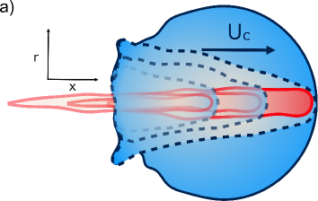
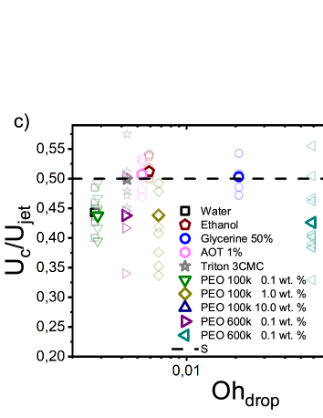
To obtain more insight into the dynamics of the cavity that is created in the droplet, we studied the cavity velocity in the positive direction, i.e. while the jet is penetrating into the droplet, as sketched in figure 8a. For each liquid we plot the average ratio of the cavity velocity and the jet velocity (bold symbols), together with the values obtained for each individual experiment (light symbols) as a function of in figure 8c. The measured and averaged values are remarkably close to the value , which is to be expected for the impact of a continuous jet on a pool, and is in agreement with previous works (Oguz et al., 1995). The slight deviation observed for the water and the PEO solutions droplets, could be due to water and PEO solution droplets being the largest ones used in the experiments. In that case, the breakup of the jet could influence , similarly to a train of droplets impacting a deep pool (Bouwhuis et al., 2016; Speirs et al., 2018b).
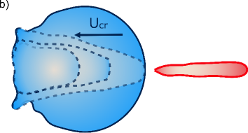
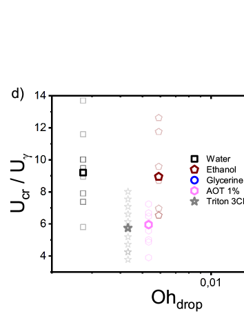
In addition to , we measured the retraction cavity velocity after the cavity reached its maximum length, as sketched in figure 7b. In figure 8d, we show rescaled by the capillary velocity scale . We observe that the average of data for the different liquids are similar, taking into consideration the data dispersion. The average of ethanol, water and aqueous glycerol mixtures are even statistically indistinguishable, given the error margins of the experiment. The lower average values of for the AOT and Triton solutions can possibly be explained by the Marangoni stresses generated by the flow from areas with low surface tension to those with high surface tension. Indeed, Marangoni stresses have been shown to retard cavity collapse and slow the velocity of Worthington jets (Jia et al., 2020; Constante-Amores et al., 2021). Therefore, we can assume that , indicating that the retraction of the cavity is surface tension driven (Michon et al., 2017). The origin of the dispersion in is associated with the jet tail breakup, where the matryoshka effect or the creation of an antibubble may arise, like in figure 5 (Speirs et al., 2018a; Song et al., 2020).
4.3 Observations after the cavity collapse
After the retraction phase, the cavity collapses and generates a Worthington jet (as e.g., depicted in the last panel of figure 3). Extensive studies of the length, speed and breakup time of a Worthington jet formed after droplet and solid impact on a liquid pool have been widely reported, and are outside of the scope of this paper (Worthington, 1908; Cheny & Walters, 1996; Gekle & Gordillo, 2010; Michon et al., 2017; Che & Matar, 2018; Mohammad Karim, 2020; Jia et al., 2020; Kim et al., 2021). Moreover, given the random breakup of the impacting jet in our experiments, the Worthington jets are observed to vary widely in size and shape, even when droplet and impacting jet consist of the same liquids. This is understandable, as it has been shown in the literature that small disturbances in the cavity can have a strong influence on the Worthington jet properties (Michon et al., 2017).
Lastly, we observe that the mixing and diffusion of the impacting jet into the droplet is governed by the droplet characteristics. Indeed, for a jet impacting a water droplet with AOT 0.1 wt below the critical value needed for traversing, there is vortical mixing (figure 9 left). Comparable mixing patterns were observed (data not shown) for the rest of the Newtonian liquids containing surfactants, and weaker mixing is seen for water, ethanol and glycerine 25 droplets. Similar mixing patterns have been described in the literature, for example, Jia et al. (2020) reported an interfacial Marangoni flow enhancing the mixing of an impacting droplet and a liquid pool with different surface tensions.
We note that in our experiments the surface tension of the jet is almost always expected to be different from the surface tension of the droplet, and a Marangoni flow could explain this type of mixing. However, a more in depth study is needed to confirm this hypothesis. In contrast, for the viscoelastic liquids with and the glycerol mixture liquids with , the jet does not mix with the droplet in the timescale of our experiments (figure 9b). Furthermore, low viscosity ( ) and low surface tension liquids reach equilibrium at a later stage than more viscous liquids () and with higher surface tension. For example, in figure 9 a PEO 600k 1 wt. droplet reaches equilibrium 4 times faster than the AOT droplet. This is expected, as surface tension and viscosity have been observed to affect droplet oscillations (Kremer et al., 2018; Arcenegui-Troya et al., 2019).
5 Conclusions
We have presented experimental results of liquid water jets impacting on pendant droplets with different liquid properties. We proposed two models to predict a critical jet impact velocity beyond which the jet traverses the droplet. First, we presented a model based on a simple energy balance between the jet kinetic energy and the change in surface tension of the droplet. The second model is based on the comparison between the Young-Laplace and the dynamic pressures of the cavity made by the penetrating jet, and its shape is described by the two-dimensional Rayleigh equation.
Although the critical velocity predicted in both models is of the same order of magnitude, they differ in their scaling relation with . The difference arises from the different description of the cavity geometry and its associated surface energy. In the energy balance model, a cylindrical shape is assumed, contrasting with the more accurate cavity shape described by the two-dimensional Rayleigh equation. Furthermore, we tested the validity of the second model, by fitting our experimental data with equation (11), showing good agreement when dynamic surface tension effects are considered, see figure 6. Therefore, for Newtonian droplets the impact process is initially dominated by inertia and their dynamic surface tension is the major opposing force.
In addition, we investigated viscoelastic effects by using water-based polyethylene-oxide solutions of varied concentrations and molecular weight. For , the droplets act as if they were Newtonian. In contrast, for , a greater jet impact speed is necessary to traverse the droplet, indicating that when the capillary and relaxation times are comparable, viscoelastic effects can dominate the traversing phenomena. Moreover, we observed a distinct transition phenomenon from traversing to embedding, which we called pearling and on which the protruing jet is sucked back into the droplet.
Next, we investigated the advancing and retraction velocities and of the cavity, confirming previous reports that for different liquids. Furthermore, we found that is surface tension driven, with the connotation that for droplets containing surfactants is observed to be slower than for the other liquids that were used, which could be explained by Marangoni stresses.
Our results are relevant for needle-free injections into skin, because of the challenge in quantifying injection processes in real tissue. Given the opacity of skin, our results bridge the gap between the jet penetration of droplets and real tissue. Our findings could also be translated to jet injections in other soft tissues, e.g. the eye, where controlling the jet velocity, , would be essential to avoid undesired tissue damage and ensure successful drug delivery.
6 Acknowledgements
This research was funded by the European Research Council (ERC) under the European Union Horizon 2020 research and innovation programme (Grant agreement No. 851630). We thank valuable discussions with Loreto Oyarte-Gálvez, Javier Rodríguez-Rodríguez, Álvaro Marín, Ivo Peters and Detlef Lohse. We also thank Ambre Bouillant and Ali Rezaei for their assistance on the shear viscosity measurements. The guidance of James W. Bales and Andrew Davidhazy through Edgerton’s Digital Collection was of great value. David Fernandez Rivas, would like to thank Gareth McKinley for his input at the start of the project and for hosting his stay at the HML and the MIT.
References
- Alvarez et al. (2010) Alvarez, Nicolas J, Walker, Lynn M & Anna, Shelley L 2010 A microtensiometer to probe the effect of radius of curvature on surfactant transport to a spherical interface. Langmuir 26 (16), 13310–13319.
- Arcenegui-Troya et al. (2019) Arcenegui-Troya, J, Belman-Martínez, A, Castrejón-Pita, AA & Castrejón-Pita, JR 2019 A simple levitated-drop tensiometer. Review of Scientific Instruments 90 (9), 095109.
- Aristoff & Bush (2009) Aristoff, Jeffrey M & Bush, John WM 2009 Water entry of small hydrophobic spheres. Journal of Fluid Mechanics 619, 45–78.
- Bergmann et al. (2006) Bergmann, Raymond, van der Meer, Devaraj, Stijnman, Mark, Sandtke, Marijn, Prosperetti, Andrea & Lohse, Detlef 2006 Giant bubble pinch-off. Physical Review Letters 96 (15), 154505.
- Bobylev et al. (2019) Bobylev, AV, Guzanov, VV, Kvon, AZ & Kharlamov, SM 2019 Influence of soluble surfactant on wave evolution on falling liquid films. In Journal of Physics: Conference Series, , vol. 1382, p. 012073. IOP Publishing.
- Bouwhuis et al. (2016) Bouwhuis, Wilco, Huang, Xin, Chan, Chon U, Frommhold, Philipp E, Ohl, Claus-Dieter, Lohse, Detlef, Snoeijer, Jacco H & van der Meer, Devaraj 2016 Impact of a high-speed train of microdrops on a liquid pool. Journal of Fluid Mechanics 792, 850–868.
- Che & Matar (2018) Che, Zhizhao & Matar, Omar K 2018 Impact of droplets on immiscible liquid films. Soft Matter 14 (9), 1540–1551.
- Cheny & Walters (1996) Cheny, JM & Walters, K 1996 Extravagant viscoelastic effects in the worthington jet experiment. Journal of Non-Newtonian Fluid Mechanics 67, 125–135.
- Constante-Amores et al. (2021) Constante-Amores, C.R., Kahouadji, L., Batchvarov, A., Shin, S., Chergui, J., Juric, D. & Matar, O.K. 2021 Dynamics of a surfactant-laden bubble bursting through an interface. Journal of Fluid Mechanics 911, A57.
- Crichton et al. (2011) Crichton, Michael L, Donose, Bogdan C, Chen, Xianfeng, Raphael, Anthony P, Huang, Han & Kendall, Mark AF 2011 The viscoelastic, hyperelastic and scale dependent behaviour of freshly excised individual skin layers. Biomaterials 32 (20), 4670–4681.
- Cu et al. (2019) Cu, Katharina, Bansal, Ruchi, Mitragotri, Samir & Rivas, David Fernandez 2019 Delivery strategies for skin: Comparison of nanoliter jets, needles and topical solutions. Annals of Biomedical Engineering pp. 1–12.
- Daerr & Mogne (2016) Daerr, Adrian & Mogne, Adrien 2016 Pendent_drop: an imagej plugin to measure the surface tension from an image of a pendent drop. Journal of Open Research Software 4 (1).
- Deng et al. (2007) Deng, Q, Anilkumar, AV & Wang, TG 2007 The role of viscosity and surface tension in bubble entrapment during drop impact onto a deep liquid pool. Journal of Fluid Mechanics 578, 119–138.
- Edgerton (1931) Edgerton, Harold E 1931 Stroboscopic moving pictures. Electrical Engineering 50 (5), 327–329.
- Eggers et al. (2007) Eggers, J, Fontelos, MA, Leppinen, D & Snoeijer, JH 2007 Theory of the collapsing axisymmetric cavity. Physical Review Letters 98 (9), 094502.
- Ferri & Stebe (2000) Ferri, James K & Stebe, Kathleen J 2000 Which surfactants reduce surface tension faster? a scaling argument for diffusion-controlled adsorption. Advances in Colloid and Interface Science 85 (1), 61–97.
- Fung (2013) Fung, Yuan-cheng 2013 Biomechanics: mechanical properties of living tissues. Springer Science & Business Media.
- Gekle & Gordillo (2010) Gekle, Stephan & Gordillo, José Manuel 2010 Generation and breakup of worthington jets after cavity collapse. part 1. jet formation. Journal of Fluid Mechanics 663, 293.
- Graham et al. (2019) Graham, Helen K, McConnell, James C, Limbert, Georges & Sherratt, Michael J 2019 How stiff is skin? Experimental dermatology 28, 4–9.
- Grotte et al. (2001) Grotte, Marie, Duprat, F, Loonis, Dominique & Piétri, Eric 2001 Mechanical properties of the skin and the flesh of apples. International Journal of Food Properties 4 (1), 149–161.
- Hamilton (1995) Hamilton, James G 1995 Needle phobia: a neglected diagnosis. Journal of Family Practice 41 (2), 169–182.
- Hogan et al. (2015) Hogan, Nora C, Taberner, Andrew J, Jones, Lynette A & Hunter, Ian W 2015 Needle-free delivery of macromolecules through the skin using controllable jet injectors. Expert Opinion on Drug Delivery 12 (10), 1637–1648.
- Jia et al. (2020) Jia, Feifei, Sun, Kai, Zhang, Peng, Yin, Cuicui & Wang, Tianyou 2020 Marangoni effect on the impact of droplets onto a liquid-gas interface. Physical Review Fluids 5 (7), 073605.
- Joodaki & Panzer (2018) Joodaki, Hamed & Panzer, Matthew B 2018 Skin mechanical properties and modeling: A review. Proceedings of the Institution of Mechanical Engineers, Part H: Journal of Engineering in Medicine 232 (4), 323–343.
- Kiger & Duncan (2012) Kiger, Kenneth T & Duncan, James H 2012 Air-entrainment mechanisms in plunging jets and breaking waves. Annual Review of Fluid Mechanics 44, 563–596.
- Kim et al. (2021) Kim, Dohyung, Lee, Jinseok, Bose, Arijit, Kim, Ildoo & Lee, Jinkee 2021 The impact of an oil droplet on an oil layer on water. Journal of Fluid Mechanics 906.
- Kiyama et al. (2019a) Kiyama, Akihito, Endo, Nanami, Kawamoto, Sennosuke, Katsuta, Chihiro, Oida, Kumiko, Tanaka, Akane & Tagawa, Yoshiyuki 2019a Visualization of penetration of a high-speed focused microjet into gel and animal skin. Journal of Visualization 22 (3), 449–457.
- Kiyama et al. (2019b) Kiyama, Akihito, Mansoor, Mohammad M, Speirs, Nathan B, Tagawa, Yoshiyuki & Truscott, Tadd T 2019b Gelatine cavity dynamics of high-speed sphere impact. Journal of Fluid Mechanics 880, 707–722.
- Kremer et al. (2018) Kremer, J, Kilzer, A & Petermann, M 2018 Simultaneous measurement of surface tension and viscosity using freely decaying oscillations of acoustically levitated droplets. Review of Scientific Instruments 89 (1), 015109.
- Krizek et al. (2020) Krizek, Jan, De Goumoëns, Frédéric, Delrot, Paul & Moser, Christophe 2020 Needle-free delivery of fluids from compact laser-based jet injector. Lab on a Chip 20 (20), 3784–3791.
- Lee et al. (1997) Lee, M, Longoria, RG & Wilson, DE 1997 Cavity dynamics in high-speed water entry. Physics of Fluids 9 (3), 540–550.
- Lorenceau et al. (2004) Lorenceau, Élise, Quéré, David & Eggers, Jens 2004 Air entrainment by a viscous jet plunging into a bath. Physical Review Letters 93 (25), 254501.
- Mercuri & Fernandez Rivas (2021) Mercuri, Magalí & Fernandez Rivas, David 2021 Challenges and opportunities for small volumes delivery into the skin. Biomicrofluidics 15 (1), 011301.
- Michon et al. (2017) Michon, Guy-Jean, Josserand, Christophe & Séon, Thomas 2017 Jet dynamics post drop impact on a deep pool. Physical Review Fluids 2 (2), 023601.
- Mohammad Karim (2020) Mohammad Karim, Alireza 2020 Experimental dynamics of newtonian and non-newtonian droplets impacting liquid surface with different rheology. Physics of Fluids 32 (4), 043102.
- Mohizin & Kim (2018) Mohizin, Abdul & Kim, Jung Kyung 2018 Current engineering and clinical aspects of needle-free injectors: A review. Journal of Mechanical Science and Technology 32 (12), 5737–5747.
- Oguz et al. (1995) Oguz, Hasan N, Prosperetti, Andrea & Kolaini, Ali R 1995 Air entrapment by a falling water mass. Journal of Fluid Mechanics 294, 181–207.
- Oyarte Gálvez et al. (2019) Oyarte Gálvez, Loreto, Brió Pérez, Maria & Fernández Rivas, David 2019 High speed imaging of solid needle and liquid micro-jet injections. Journal of Applied Physics 125 (14), 144504.
- Oyarte Gálvez et al. (2020) Oyarte Gálvez, Loreto, Fraters, Arjan, Offerhaus, Herman L, Versluis, Michel, Hunter, Ian W & Fernández Rivas, David 2020 Microfluidics control the ballistic energy of thermocavitation liquid jets for needle-free injections. Journal of Applied Physics 127 (10), 104901.
- Padilla-Martínez et al. (2014) Padilla-Martínez, JP, Berrospe-Rodriguez, C, Aguilar, G, Ramirez-San-Juan, JC & Ramos-Garcia, R 2014 Optic cavitation with cw lasers: A review. Physics of Fluids 26 (12), 122007.
- Prausnitz et al. (2004) Prausnitz, Mark R, Mitragotri, Samir & Langer, Robert 2004 Current status and future potential of transdermal drug delivery. Nature Reviews Drug discovery 3 (2), 115–124.
- Rastopov & Sukhodolsky (1991) Rastopov, Stanislav F & Sukhodolsky, Anatoly T 1991 Sound generation by thermocavitation-induced cw laser in solutions. In Optical Radiation Interaction with Matter, , vol. 1440, pp. 127–134. International Society for Optics and Photonics.
- Rodríguez et al. (2017) Rodríguez, Carla Berrospe, Visser, Claas Willem, Schlautmann, Stefan, Rivas, David Fernandez & Ramos-Garcia, Ruben 2017 Toward jet injection by continuous-wave laser cavitation. Journal of Biomedical Optics 22 (10), 105003.
- Sokolowski et al. (2010) Sokolowski, Chester J, Giovannitti, Joseph A & Boynes, Sean G 2010 Needle phobia: etiology, adverse consequences, and patient management. Dental Clinics 54 (4), 731–744.
- Song et al. (2017) Song, Meirong, Ju, Jie, Luo, Siqi, Han, Yuchun, Dong, Zhichao, Wang, Yilin, Gu, Zhen, Zhang, Lingjuan, Hao, Ruiran & Jiang, Lei 2017 Controlling liquid splash on superhydrophobic surfaces by a vesicle surfactant. Science Advances 3 (3), e1602188.
- Song et al. (2020) Song, Youngsup, Zhang, Lenan & Wang, Evelyn N 2020 Criteria for antibubble formation from drop pairs impinging on a free surface. Physical Review Fluids 5 (12), 123601.
- Speirs et al. (2018a) Speirs, NB, Mansoor, MM, Hurd, RC, Sharker, SI, Robinson, WG, Williams, BJ & Truscott, Tadd T 2018a Entry of a sphere into a water-surfactant mixture and the effect of a bubble layer. Physical Review Fluids 3 (10), 104004.
- Speirs et al. (2018b) Speirs, Nathan B, Pan, Zhao, Belden, Jesse & Truscott, Tadd T 2018b The water entry of multi-droplet streams and jets. Journal of Fluid Mechanics 844, 1084.
- Truscott et al. (2014) Truscott, Tadd T, Epps, Brenden P & Belden, Jesse 2014 Water entry of projectiles. Annual Review of Fluid Mechanics 46, 355–378.
- Wang et al. (2019) Wang, Ting, Si, Yifan, Luo, Siqi, Dong, Zhichao & Jiang, Lei 2019 Wettability manipulation of overflow behavior via vesicle surfactant for water-proof surface cleaning. Materials Horizons 6 (2), 294–301.
- Worthington (1908) Worthington, Arthur Mason 1908 A study of splashes. Longmans, Green, and Company.
- Zhu et al. (2000) Zhu, Yonggang, Oğuz, Hasan N & Prosperetti, Andrea 2000 On the mechanism of air entrainment by liquid jets at a free surface. Journal of Fluid Mechanics 404, 151–177.