Millimeter-Wave Beamforming with Continuous Coverage for Mobile Interactive Virtual Reality
Abstract
Contemporary Virtual Reality (VR) setups commonly consist of a Head-Mounted Display (HMD) tethered to a content-generating server. ”Cutting the wire” in such setups and going truly wireless will require a wireless network capable of delivering enormous amounts of video data at an extremely low latency. Higher frequencies, such as the millimeter-wave (mmWave) band, can support these requirements. Due to high attenuation and path loss in the mmWave frequencies, beamforming is essential. For VR setups, beamforming must adapt in real-time to the user’s head rotations, but can rely on the HMD’s built-in sensors providing accurate orientation estimates. In this work, we present coVRage, a beamforming solution tailored for VR HMDs. Based on past and current head orientations, the HMD predicts how the Angle of Arrival (AoA) from the access point will change in the near future, and covers this AoA trajectory with a dynamically shaped beam, synthesized using sub-arrays. We show that this solution can cover such trajectories with consistently high gain, unlike regular single-beam solutions.
I Introduction
A wide variety of Virtual Reality (VR) applications have been investigated over the years, in fields including education, medicine and manufacturing [1, 2, 3]. Such applications require a reliable high-throughput and low-latency connection to an external device providing VR content [4]. This may be live video recorded elsewhere, such as for remote collaboration or meetings, or 3D graphics generated on a PC or edge cloud, such as for gaming applications. The recently introduced Oculus Quest 2 Head-Mounted Display (HMD) is capable of generating content on-device and thereby working without any connection to other devices. As this restricts the device from running many such connected and computationally intensive applications, it also offers the option to tether it to a PC. This setup, along with most others currently on the market, relies on a wired connection for content delivery. While this easily meets reliability, latency and throughput requirements, it limits the user’s range of movement, hindering true immersion.
To achieve truly wireless connected HMDs, millimeter-wave (mmWave) networking, in the to band, is most often considered, as lower frequencies cannot meet the VR requirements [4]. Solutions often rely on the existing IEEE 802.11ad and IEEE 802.11ay Wi-Fi standards for mmWave [5] or on 5G NR’s mmWave capabilities [6].
The main challenges in building such a system stem from mmWave’s inherently high path loss and attenuation. To achieve sufficiently high signal strength at the HMD, the transmitter and the HMD must both focus their energy towards each other, in a process called beamforming. MmWave transceivers usually implement beamforming using phased antenna arrays, consisting of many separate antenna elements [7]. The path lengths of the signal from each element will differ slightly in a given direction, meaning the different signals are generally not phase-aligned. By carefully shifting the phase of each element, a beamforming algorithm ensures signals towards an intended receiver are phase-aligned and therefore at maximum amplitude. As this phenomenon also applies to signals received at phased arrays, beamforming should also occur when in receive mode, focusing towards the transmitter. While basic beamforming consists of a single beam in one direction, we exploit a more advanced approach using a variable number of sub-beams. By subdividing the array into sub-arrays providing sub-beams, the combined beam can cover a dynamically shaped area.
Such flexible coverage is highly advantageous for beamforming on an HMD. An angular beam misalignment of a few degrees can have a significant impact on Signal-to-Noise Ratio (SNR) [8], and a human head can reach an instantaneous angular velocity of hundreds of degrees per second [9, 10, 11]. As such, a flexibly shaped beam, stretched in the direction of a head rotation, can provide an HMD with consistently high receive gain, essential for uninterrupted low-latency video delivery. To form such a beam proactively, head rotations must be accurately predicted. Fortunately, HMDs are, by design, equipped with orientation estimation capabilities. Current and historical estimations enable the design of reasonably accurate predictors of future orientations and rotations.
In this paper, we present coVRage, a novel beamforming method for HMDs, supporting uninterrupted connectivity during rapid head movements. This is, to the best of our knowledge, the first HMD-focused beamforming method offering proactive Angle of Arrival (AoA) trajectory coverage through sub-arrays. Using simulation, we demonstrate that coVRage provides a stable gain in a single-user VR scenario.
The remainder of this paper is organised as follows. In Section II, we provide background and related work on sub-arrays, mmWave VR and head rotation prediction. Section III investigates how phased arrays may be placed within an HMD, along with an appropriate system model. Section IV outlines how to represent 3D orientations. Next, Section V presents coVRage, and in Section VI we evaluate how well it performs in simulation. Finally, Section VII concludes this paper.
II Background and Related Work
II-A Sub-arrays
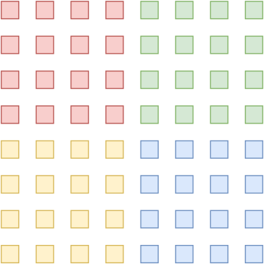
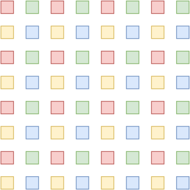
To form beams of flexible size and shape, sub-arrays are crucial. Therefore, we provide an overview of sub-arrays and the related literature. A sub-array may be either localized, with all elements adjacent, or interleaved, with elements spread across the entire array, as illustrated in Fig. 1. The sub-array configuration can be supported at a hardware level, by having multiple RF chains, allowing each sub-array to send a different signal. This includes hybrid arrays, with one chain per sub-array, and digital arrays, with one chain per element [12]. When only one RF chain is available for all elements, the array is called analog. Several works present design decisions for hybrid and digital arrays for localized [13, 14, 15, 16] or interleaved [12, 17] sub-array antennas. Zhang et al. compare the two in terms of performance and feasibility [18]. For beamforming with hybrid arrays, many approaches have been proposed. These may either form a single main lobe [19, 20], or provide simultaneous coverage for multiple users [21, 22, 23, 24]. The hybrid phased array has also been used to design hierarchical codebooks, facilitating a binary-search approach to beamforming with gradually narrowing beams [25]. Physical sub-arrays, based on the array’s design, can be further subdivided into logical sub-arrays. This allows for more flexible hierarchical codebook design [26]. Such codebooks can also be designed with logical sub-arrays only, which only requires an analog array [27, 28, 29]. Multi-user coverage with logical sub-arrays has also been investigated, both by assigning a sub-array per user [30], or by synthesizing one large beam of flexible shape, covering all recipients [31]. Our algorithm extends this final approach to cover the upcoming trajectory of one peer, rather than the current locations of several peers.
II-B Wireless VR
Several works have considered mmWave for cutting the cord in VR. In the MoVR solution, a ceiling-mounted relay assists the Access Point (AP) at the edge of the playing field [8]. The HMD’s built-in location and orientation tracking is used to steer transmit and receive beams directly at peers. Zhong et al. present a programmable mmWave wireless solution using Commercial Off-The Shelf (COTS) hardware and investigate rendering-based optimizations [32]. Other works further investigate such optimizations [33, 34]. Elbamby et al. outline the challenges of mmWave VR [4]. Na et al. measure attainable VR throughput with COTS IEEE 802.11ad hardware [5]. The IEEE 802.11ad standard was shown to be a good fit for interactive VR, with its channel access settings having a significant impact on the attainable datarate [35]. Kim, Lee and Lee propose a dynamic power control algorithm for energy-efficient VR delivery over IEEE 802.11ad [36]. Several proposed designs incorporate falling back to legacy Wi-Fi to cover mmWave signal loss [37, 6]. In case of pre-recorded VR content, frames can be sent proactively over mmWave using predicted future viewing directions [38]. Pose information-assisted networks leverage location and orientation measurements from on-device sensors, such as in HMDs, for beam selection as well as AP selection, focused on spatial sharing between clients [39]. Finally, OScan proposes fast 3D beam steering for mobile clients such as HMDs, using UV-coordinates [9]. Of these works, only OScan considers HMD-side beamforming, but it does not support proactively covering upcoming AoAs. As such, our work is complementary to most of the aforementioned works.
II-C Head Rotation Prediction
Several approaches of varying complexity have been considered for head rotation prediction. A variety of works has shown the effectiveness of classical approaches such as autoregression and Kalman filters for head rotation estimation and prediction [40, 41, 42, 43]. The more recent field of viewport prediction essentially solves the same problem [44, 45]. Recent work uses deep learning to further improve the results [46], and may use video content as additional inputs [47]. While the different approaches are difficult to compare directly due to varying prediction horizons and datasets, most approaches provide predictions amply accurate for our application. Several of the above approaches achieve an average error under a third of that of a baseline predictor which outputs the latest known orientation as prediction.
III Assumptions and System Model
In this section, we describe the environment coVRage is expected to operate in, provide array design guidelines based on this environment, and outline an appropriate system model.
III-A Expected Environment
CoVRage considers a VR setup where a ceiling-mounted mmWave AP serves an HMD-wearing user on the ground. The user can freely rotate their head. Within the time span of a single rotation, the user’s location is expected to remain static (the location intuitively changes more slowly than the rotation). The AP is assumed to run some beamforming algorithm enabling it to always perfectly focus its beam at the HMD. The HMD can estimate its own orientation with high accuracy, and can accurately predict its orientation in the near future [48, 49]. Given this orientation, the HMD is able to derive the direction towards the AP. The HMD is equipped with a mmWave phased array. The goal of coVRage is then to tune the receive beam of the HMD such that the received signal strength is consistently high while the HMD rotates towards the predicted orientation. CoVRage achieves this by synthesizing a beam covering the entire (shortest) trajectory between the current and predicted orientation. The prediction horizon should be large enough to encompass a single fast head movement, e.g., .
III-B Antenna Array Design
The antenna array for the HMD should be designed with the expected environment outlined above in mind. We provide some guidelines, then present a specific design.
First of all, we eliminate hybrid and digital arrays. While their many RF chains would offer more flexible beamforming, their power consumption and cost are prohibitive for a battery-powered consumer device [28]. We therefore opt for an analog array. A next trade-off to consider is between the number of elements in the array, and the spacing between these elements. For an -element Uniform Linear Array (ULA), the attainable beamwidth in radians is
| (1) |
at a steering angle ( being broadside), with an inter-element spacing of . Such a ULA, with all elements on one line, will however not suffice, as it can only beamform with one degree of freedom [50]. As coVRage requires 3D beamforming, with both azimuth and elevation of the beam controllable, a Uniform Rectangular Array (URA) is needed. For a URA of size aimed at , the azimuthal and elevational beamwidths are calculated separately, replacing and in (1) with either and or with and . The beamwidth equation implies that, for a fixed physical area, adding more elements within said area will not tighten the beamwidth. As such, an inter-element spacing of is often used throughout the industry, as a tighter spacing leads to unwieldily wide beams, while wider spacing is known to create grating lobes; undesired side lobes with a directional gain as high as the main lobe’s. This rule of thumb, however, no longer applies when using interleaved sub-arrays. With interleaved sub-arrays in a URA, the inter-element spacing within the sub-array is is , as illustrated by Fig. 1b. As such, the physical inter-element spacing should be chosen with a specific in mind. Whenever the sub-beams that these interleaved sub-arrays can create are unable to cover a full trajectory, they should be further subdivided into sub-sub-arrays, which would be localized within the sub-array.
For the remainder of this paper, we consider a specific instantiation of the phased array within the HMD. Measuring many modern HMDs showed that a square URA of length is feasible. We will use the band, as this unlicensed band is free to use, and already widely used for mmWave Wi-Fi. Then, we use interleaved sub-arrays, meaning the inter-element spacing becomes . At this configuration, creating sub-sub-arrays would lead to rather large beams, meaning this is mainly a feasible option for higher frequencies. At , often considered the upper limit of mmWave, a sub-sub-array could consist of elements, having a beamwidth of only .
III-C System Model
CoVRage is a receiver-side beamforming method, which assumes a Line-of-Sight (LoS) path always exists and ignores reflected paths111With the indoor ceiling-to-floor transmissions we consider, LoS is unlikely to be broken. First-order reflections are most likely via walls, and their power is assumed to be negligible as long as the user is not right next to the wall and grating lobes are avoided. Redirected walking [51] can keep mobile users away from walls.. As such, we opt for a simple system model [36, 52, 53], calculating the received power as
| (2) |
where and are input and received power in , and are transmitter and receiver gain in and is the path loss over meters in .
Transmitter-side beamforming is assumed to be perfect222If pose information is forwarded from HMD to AP, beamforming at the (static) AP is considerably simpler than at the (rotating) HMD, and therefore considered to be solved for the purpose of our channel model., so the transmitter’s Effective Isotropic Radiated Power (EIRP) is constantly at the maximum legally allowed strength ( in Europe), and
| (3) |
Using the well-known log-distance path loss model, we approximate the path loss as
| (4) |
where is the transmitter-receiver distance in meters, is some reference distance, is the path loss exponent and is the Friis free-space path loss over :
| (5) |
where is the wavelength. The path loss exponent is estimated as for an indoor LoS mmWave setting [54], so given a wavelength of for , and using , the model simplifies to approximately
| (6) |
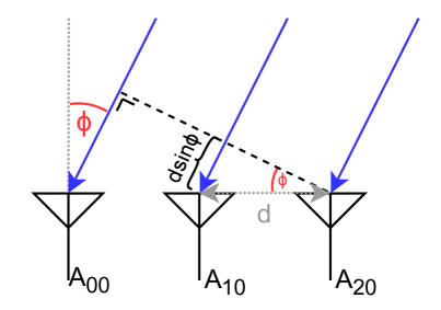
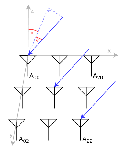
To determine the receiver gain, we first determine the phase shift between antenna elements. For a URA of size , using element as reference element, the phase shift becomes [50]
| (7) |
for element with an AoA of azimuth and elevation , as illustrated in Fig. 2. Then, the phase shifters of the receive array are configured with Antenna Weight Vector (AWV) with complex elements each with magnitude 1, such that the received signal is modified with coefficient
| (8) |
such that the final directional receive gain in for some AWV and AoA is
| (9) |
where may be omitted for brevity when they represent the AoA.
To beamform the receiver towards a specific direction, its gain must be maximized. For this, the weight elements of weight must be set to:
| (10) |
IV Orientations and directions
Several methods of representing orientations and directions in 3D space have seen common use over the years [55, 56, 57]. Each has its own advantages and disadvantages, meaning no single most useful representation exists, and care must be taken to select the most appropriate representation for an application. These representations may vary in interpretability, compactness, uniqueness, numerical stability, computational efficiency, ease of combination/subdivision and susceptibility to gimbal lock. Different graphical VR engines supply user orientations in different representations, and throughout coVRage several representations are deliberately used to exploit their advantages.
IV-A Representations
An easily interpretable representation is that of the Euler angles. In this system, an orientation is described by three chained rotations around the three axes of the coordinate system, where this coordinate system rotates along with the body. As 3D rotations are not commutative, the order of orientations must be properly defined.
The separate rotations are often referred to as yaw, pitch and roll, assigned the variables , and respectively.
This is easily converted from an orientation to a direction; by simply omitting the final rotation, a direction in 3D space is represented compactly. In this interpretation, the two remaining rotations are frequently called the azimuth and elevation.
In graphical engines, rotations are often represented by unit quaternions. Quaternions, first covered in the mid 19th century, are an extension of complex numbers, containing three imaginary units , and , all equal to when squared, rather than just the one. In this paper, we represent the quaternion as the vector . The set of unit quaternions (i.e., of norm 1) is a double-cover of the 3D rotation group, meaning that for each rotation in 3D space, exactly two unit quaternion representations exist ( and , as negating both the magnitude and axis of a rotation results in the same rotation). Quaternions are mathematically convenient; they are numerically stable, do not suffer from gimbal lock and are computationally efficient. Furthermore, quaternions are easily combined by simply multiplying them using the Hamilton product. When representing a vector as quaternion , the product , where is the complex conjugate, represents rotated by . Interpolation and extrapolation are also simple: maintains the rotational axis but multiplies the magnitude by .
As a final representation, we consider uv-coordinates [58, 9]. , consisting of only two real variables, only has enough degrees of freedom to represent directions in 3D, similar to the azimuth-elevation representation. UV-coordinates however exist in sine-space, meaning covers a hemisphere whose center is equivalent to azimuth and elevation 0.
Why these coordinates are commonly used for beamforming is outlined in Section V-A2.
IV-B Conversions
As different components within the beamforming system presented in this paper require different representations of orientations and directions, we often need to convert between them. The following conversions are used for the remainder of the paper.
IV-B1 Quaternions to Euler angles
To convert a quaternion to Euler angles , calculate [55]:
| (11) | ||||
where the arctangent must be implemented using the atan2 function, returning a result in .
IV-B2 Euler angles to UV-coordinates
For this conversion, first convert the orientation to a direction, by simply discarding the roll . Then, the UV-coordinates are [9]
| (12) | ||||
Note that this definition differs from the one commonly used for the similar UV-mapping in graphical engines, which covers the full sphere.
IV-B3 UV-coordinates to Euler angles
In the opposite direction, and can be recovered as
| (13) | ||||
again using atan2 in the implementation. This clearly shows that not every is a valid coordinate. If , the azimuth is no longer a real number, meaning such coordinates are invalid.
V CoVRage
In this section, we provide a step-by-step explanation of how coVRage works, along with a brief analysis of its computational efficiency.
V-A The Algorithm
CoVRage must convert measured current and predicted future HMD orientations to a set of phase shifts for the phased array in the HMD. We decompose this process into three distinct steps. First, we determine how the AP appears to move relative to the HMD, the reference point. Specifically, we determine the direction of the AP at the start and end of the rotation between HMD orientations, and the shortest trajectory between these directions, in UV-space. Next, we determine a set of beams that covers this trajectory, achievable by the phased array. Finally, we minimize the destructive interference between the sub-arrays on the trajectory, to avoid having ”blind” spots along the trajectory.
V-A1 Trajectory Generation
To present trajectory generation, we borrow some terminology from 3D graphics. All objects in 3D space are located relative to the world coordinate system, which is attached to the HMD. During a head rotation, this world coordinate system rotates. It is simple to see that this is equivalent to applying the inverse rotation, around the world coordinate system, to all other objects in 3D space.
In quaternion terms, the HMD rotates from orientation to by rotation , meaning the AP will appear to perform the rotation around the user. To translate rotations to absolute directions, the AP direction at one point must be known. This can be hard-coded, or measured using existing AP sensing approaches [39].
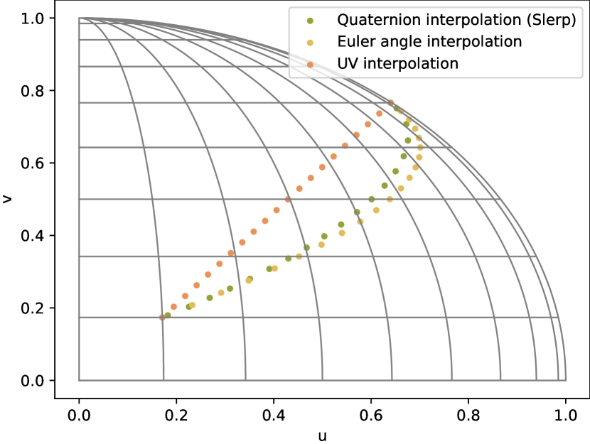
As the HMD is only expected to provide the start and end of the expected rotation within some brief time-frame, coVRage is responsible for generating the path of the AP direction during the rotation, between those two points. The representation of the orientation depends on the used framework. OpenVR provides rotation matrices, Unreal uses Euler angles and Unity gives quaternions. The goal of this step was to determine the AP trajectory in UV-space, so some conversion is definitely required. Furthermore, determining the shortest trajectory between two orientations (i.e., a single rotation, known to exist from Euler’s rotation theorem) is not straightforward with UV-coordinates. To generate this UV-space trajectory, we will need to first generate it in another representation, sample some points from it, and convert those to UV-coordinates. More directly, we need to interpolate between the points. In the 3D graphics world, it is widely known that naive interpolation does not work well with rotation matrices and Euler angles [59], as this does not generate orientations on the shortest trajectory between the reference orientations. Quaternions, on the other hand, are known to be a perfect fit for interpolation. Given two quaternions and , the quaternion represents the rotation from the orientation represented by to that represented by . The set of quaternions for covers exactly all intermediate orientations achieved during said rotation. This algorithm is known as Spherical linear interpolation (Slerp) and widely used in 3D graphics [59]. The resulting quaternions are easily converted to UV-coordinates using (11) and (12).
As trajectories have only a modest curve in UV-space, this approximation is very close. Fig. 3 shows interpolations performed with quaternions, Euler angles and UV-coordinates. As only the quaternion-based interpolation provides the shortest path, this is used in coVRage.
V-A2 Sub-Beamforming
Once the AP trajectory as seen from the HMD is determined, the algorithm needs to synthesize a beam covering it. As the beam will consist of a variable number of sub-beams from sub-arrays, the number of beams, and, as an effect, their width, must first be determined. Here, the choice for UV-coordinates becomes clear. Remember from (1) that the beamwidth depends on the angular distance from broadside (). In UV-coordinates however, the beamwidth is nearly invariant to the beam’s direction [58]. As such, the beamwidth in UV-space can be approximated by the constant
| (14) |
with an error always under , highest near the edges of the hemisphere. As shown in Fig. 4, a rectangular sub-array’s beam anywhere in UV-space is as such accurately represented by a circle of constant radius, eliminating the need for complicated, time-consuming beam shape calculations. The problem of trajectory coverage with sub-beams is essentially reduced to covering a curve using circles. The first substep here is to determine how many beams are needed to cover the entire trajectory, noting that more beams means fewer elements per beam and therefore wider beams. Estimate the trajectory length as the sum of distances between adjacent UV-space trajectory points. We will aim the first sub-beam towards the current direction, then divide the remaining beams along the trajectory such that each point lies within at least one sub-beam’s beamwidth. When each interleaved sub-array has a beamwidth of (0.111 for ), the required number of sub-arrays is
| (15) |
as only half the beamwidth of the first sub-beam, aimed at the first point, covers the trajectory. Experimentation showed that aiming the first sub-beam such that the first point is at the edge of its beamwidth provided insufficient coverage at that first point.
If exceeds the available number of interleaved sub-arrays (4 for the array), each must be further subdivided into localized sub-sub-arrays. For each subdivision, each sub-beam’s width doubles and the number of sub-beams quadruples, meaning the required number of subdivisions is the minimal value of for which
| (16) |
As the coverable trajectory length at is already over for , this is mainly of practical use with higher frequencies.
Another possibility is that fewer than the available number of interleaved sub-arrays are needed. Some approaches choose to simply deactivate unneeded sub-arrays [28], which requires hardware support. We instead reinforce sub-beams by steering multiple sub-arrays in the same direction. When only one sub-array is needed, all are aimed in the same direction, effectively eliminating the sub-arraying mechanism entirely. With two sub-beams required, diagonally located pairs of sub-arrays steer towards the same direction. Finally, when three of the four are needed, the first sub-beam, closest to the current AP direction, is formed by two diagonally located sub-arrays.
Once the number of beams is determined, aiming these is relatively straightforward. CoVRage iterates through the available sample points on the trajectory curve and determines for each point if a beam should be aimed towards it. This is determined by checking if a sub-beam focused at the point would cover all previously considered points not yet covered by a previous sub-beam. As long as this is the case, no candidate sub-beams are locked in. However, once a candidate sub-beam could no longer cover all as of yet uncovered previous points, the candidate sub-beam at the previous point is selected. To avoid coverage gaps between two adjacent sample points, we may require that a sub-beam also covers the most recently considered point already covered by the previously selected sub-beam. As such, two consecutive sub-beams will overlap at (at least) one sample point. With this algorithm, a sub-beam covering the final part of the trajectory may not be found. If this occurs, we extrapolate the trajectory and continue the algorithm until all original sample points are covered. The current implementation uses a simple linear extrapolation using the final two sample points. Using this set of sub-beams, phase shift weights for sub-beam syncing can be calculated. Experiments showed that the impact of how sub-beams are mapped to sub-arrays is negligible.
To calculate the sub-AWV of the -th sub-array, (10) still applies, with and being the element indices within the sub-array. To construct the full AWV, we first introduce helper functions and , which map array-wide element coordinates to the index of the sub-array said element is assigned to, and to the coordinates within that sub-array, respectively. The elements of the full AWV are then
| (17) |
where contains sub-array-level phase shifts, detailed in the following subsection. The first two functions in Algorithm 1 summarize this step.
V-A3 Sub-Beam Syncing
Once the sub-array layout is determined and each sub-array is aimed properly, the remaining step is to synchronize the sub-beams, eliminating destructive interference between sub-arrays along the trajectory. As global optimisation at this level is challenging and expensive, we apply a heuristic inspired by previous work on analog sub-arrays [31]. Specifically, we minimize destructive interference between adjacent sub-beams where it is expected to be the most impactful. In this case, this is the point along the trajectory equidistant from the two sub-beams. Sub-beam selection in Section V-A2 was carefully designed to ensure (at least) one sample point of overlap between adjacent beams’ coverages. The algorithm iterates through all adjacent sub-beam pairs, determines the phase difference between the two sub-beams at the overlapping point, and applies a uniform additional phase shift to all elements of the second sub-beam, making the two sub-beams phase-aligned at the overlapping sample point. To determine the phase difference of sub-beams and (where ) at point , first convert this point to Euler angles using (13). Then determine and by applying (8) with the elements of only sub-array or . Then set the sub-array-level phase shift such that it undoes this phase difference at sub-array :
| (18) |
where denotes the angle (i.e., the phase) of the complex value. For the first sub-beam, there is no phase shift: . The third function in Algorithm 1 summarizes this step.
V-B Computational Complexity
As coVRage is designed to run in real-time on an HMD, it must be computationally efficient. The entire procedure consists of closed-form expressions. The first and third functions in Algorithm 1 are of complexity with the trajectory length. Considering the limitations of human head movement, also approximates their complexity. The second function is with the sampled points on the trajectory. If required, the sampling rate can be reduced to meet any beamforming deadlines. Any calculated sub-beam direction differs from the optimal direction by at most one sampling interval.
VI Evaluation
In this section, we simulate coVRage to evaluate how well it performs in the envisioned scenario. First, we assess its performance in its trajectory-covering goal. Then, we analyse the performance within the VR application, assessing the impact on attainable datarate using mmWave Wi-Fi.
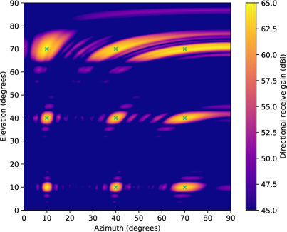
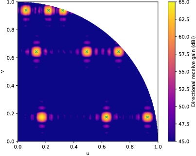
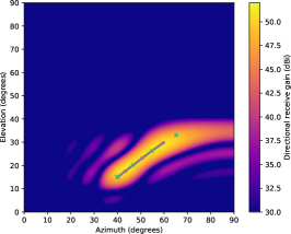
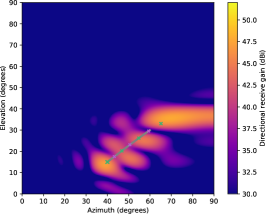
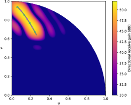
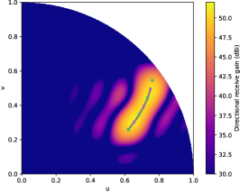
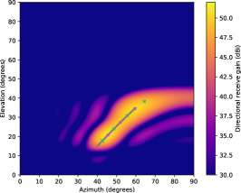
To evaluate coVRage, we simulate the array, and select two AP trajectories requiring all 4 interleaved sub-arrays to be fully covered. Fig. 5 shows the directional receive gain, calculated using (9) with both Euler angles and UV-coordinates. For clarity, all gains are raised to at least , and only half the hemisphere is shown. This clearly shows that the gain along the entire trajectory is consistently high. Some deviation from the predicted trajectory is also inherently supported with this beamwidth, without losing excessive energy far away from the trajectory. This provides coVRage with some inherent robustness to prediction errors that may occur with contemporary prediction methods. In trajectory B, extrapolation provided the final sub-beam direction.
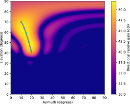
Next, Fig. 5e and 5f illustrate the advantage of some coVRage design decisions. In Fig. 5e, sub-beam syncing is disabled, instead using arbitrary, implementation-dependent sub-array-level phase shifts. Overall, the gain is lower, with coverage near the midpoints being especially poor. This indicates that sub-beam syncing is essential to the proper working of the algorithm. In Fig. 5f, the first sub-beam is not placed at the first trajectory point, but rather at the farthest point whose beam still covers the first point. As there is no sub-beam syncing aimed at optimising gain at this first point, its gain decreases by compared to having a sub-beam pointed directly at it. As this is the actual AP direction at the time of beamforming, high coverage for this point is arguably the most important.
Next, we evaluate how coVRage compares to steering only a single beam in one specific direction. We consider three possible directions: (1) towards the current AP direction, (2) at the farthest trajectory point still covering the current position and (3) halfway along the trajectory. As the single beam uses the full array, with only half the inter-element spacing of the sub-arrays, this beam will be twice as wide as any sub-beam. Using the two trajectories from Fig. 5, we measure the directional receive gain along the entire trajectory using coVRage and the three single-beam approaches. As Fig. 6a and 6b show, the algorithm’s coverage of the trajectory is very consistent. In trajectory A, the gain range is , largely due to a decrease at the the end of the trajectory. With trajectory B, the final sub-beam is aimed beyond the final trajectory point, meaning coverage remains very stable throughout, with a range of only . Higher coverage at the end of the trajectory could be enforced by requiring a final sub-beam beyond the trajectory.
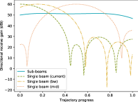
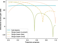
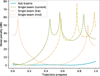
The single-beam approaches, as expected, manage to outperform coVRage at and around their steering direction. Away from that direction, however, gain reduces quickly, in contrast to coVRage.
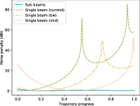
In analyzing the impact on SNR, both the receive gain in the AoA direction and the maximum receive gain are of importance. The former determines the intensity of the intended signal, while the latter influences that of the noise, assuming it is isotropic. Therefore, we quantify the approximate impact of gain fluctuations throughout the trajectory using a penalty
| (19) |
for some AoA. This decibel-scale term can be subtracted from the SNR directly, and therefore represents the SNR loss caused by high directional gain away from the AoA (but possibly elsewhere along the trajectory). As long as the maximum directional gain lies along the trajectory, the gain fluctuation along the trajectory also sets an upper bound to this noise penalty. Fig. 6c and 6d show the penalty for the two trajectories under consideration. To assess this penalty’s impact on performance, we rely on the IEEE 802.11ad standard’s minimum received signal intensity for each Modulation and Coding Scheme (MCS) [36, 60]. From the highest to lowest non-control MCS, offering and throughput respectively, the required intensity drops by . As such, when using any single-beam solution, even if the maximum SNR is an exceptionally high above the requirement for maximum MCS, it will drop so low along the trajectory that the datarate reverts to a control-level or connectivity is even lost altogether. Either halts delivery of video content to the HMD and is extremely disruptive to the user experience. Ignoring the coverage reduction at the end of trajectory A, a maximum SNR of just above the required SNR of the highest MCS will suffice to maintain the maximum datarate throughout the trajectory. This was previously shown to be sufficient to serve multiple 4K HMDs at and a transmission latency under [35]. Hence, our solution can, in contrast to single-beam solutions, support truly wireless contemporary immersive VR setups.
VII Conclusion
In this paper, we presented coVRage, the first beamforming algorithm designed specifically for HMD-side beamforming with mobile VR, where uninterrupted reception even during fast head rotations is crucial for maintaining user experience. Using the HMD’s built-in orientation detection capabilities, a predictor can estimate how the AoA of incoming wireless video data will change in the near future. By subdividing the phased array into sub-arrays and aiming each sub-array’s beam at a different point along the predicted trajectory, coVRage is able to guarantee uninterrupted coverage along the full trajectory, at a very stable signal strength. Simulations using a simple channel model show that coVRage can design beams with a signal strength variation of only a few decibels. A single-beam solution is shown to instead vary by tens of decibels, enough to decimate the attainable throughput, therefore causing a substantial negative impact on, or even fully impairing the end-user’s experience. In future work, we will further investigate capabilities with different array configurations and frequencies. Furthermore, we will quantify the impact of prediction errors and of residual destructive interference between sub-beams, and if needed harden the algorithm against this. Finally, we will combine coVRage with specific trajectory predictors and AP-side beamforming to evaluate the performance of an end-to-end system.
Acknowledgment
The work of Jakob Struye was supported by the Research Foundation - Flanders (FWO): PhD Fellowship 1SB0719N. The work of Filip Lemic was supported by the EU Marie Skłodowska- Curie Actions Individual Fellowships (MSCA-IF) project Scalable Localization-enabled In-body Terahertz Nanonetwork (SCaLeITN), grant nr. 893760. In addition, this work received support from the University of Antwerp’s University Research Fund (BOF).
References
- [1] L. P. Berg and J. M. Vance, “Industry use of virtual reality in product design and manufacturing: a survey,” Virtual reality, vol. 21, no. 1, pp. 1–17, 2017.
- [2] J. Radianti, T. A. Majchrzak, J. Fromm, and I. Wohlgenannt, “A systematic review of immersive virtual reality applications for higher education: Design elements, lessons learned, and research agenda,” Computers & Education, vol. 147, p. 103778, 2020.
- [3] L. Li, F. Yu, D. Shi, J. Shi, Z. Tian, J. Yang, X. Wang, and Q. Jiang, “Application of virtual reality technology in clinical medicine,” American journal of translational research, vol. 9, no. 9, p. 3867, 2017.
- [4] M. S. Elbamby, C. Perfecto, M. Bennis, and K. Doppler, “Toward low-latency and ultra-reliable virtual reality,” IEEE Network, vol. 32, no. 2, pp. 78–84, 2018.
- [5] W. Na, N.-N. Dao, J. Kim, E.-S. Ryu, and S. Cho, “Simulation and measurement: Feasibility study of tactile internet applications for mmwave virtual reality,” ETRI Journal, vol. 42, no. 2, pp. 163–174, 2020.
- [6] Y. Liu, J. Liu, A. Argyriou, and S. Ci, “Mec-assisted panoramic vr video streaming over millimeter wave mobile networks,” IEEE Transactions on Multimedia, vol. 21, no. 5, pp. 1302–1316, 2019.
- [7] D. Tse and P. Viswanath, Fundamentals of Wireless Communication. USA: Cambridge University Press, 2005.
- [8] O. Abari, D. Bharadia, A. Duffield, and D. Katabi, “Enabling high-quality untethered virtual reality,” in 14th USENIX Symposium on Networked Systems Design and Implementation (NSDI 17), Boston, MA, Mar. 2017, pp. 531–544.
- [9] A. Zhou, L. Wu, S. Xu, H. Ma, T. Wei, and X. Zhang, “Following the shadow: Agile 3-d beam-steering for 60 ghz wireless networks,” in IEEE INFOCOM 2018 - IEEE Conference on Computer Communications, 2018, pp. 2375–2383.
- [10] X. Corbillon, F. De Simone, and G. Simon, “360-degree video head movement dataset,” in Proceedings of the 8th ACM on Multimedia Systems Conference, 2017, p. 199–204.
- [11] S. Fremerey, A. Singla, K. Meseberg, and A. Raake, “Avtrack360: An open dataset and software recording people’s head rotations watching 360° videos on an hmd,” in Proceedings of the 9th ACM Multimedia Systems Conference, 2018, p. 403–408.
- [12] T. Shimura, T. Ohshima, H. Ashida, S. Ishikawa, S. Fujio, A. Honda, Z. Li, K. Nishikawa, C. Kojima, K. Ozaki, M. Shimizu, and Y. Ohashi, “Millimeter-wave tx phased array with phase adjusting function between transmitters for hybrid beamforming with interleaved subarrays,” in 2016 46th European Microwave Conference (EuMC), 2016, pp. 1572–1575.
- [13] R. J. Mailloux, “Subarray technology for large scanning arrays,” in The Second European Conference on Antennas and Propagation, EuCAP 2007, 2007, pp. 1–6.
- [14] O. El Ayach, R. W. Heath, S. Rajagopal, and Z. Pi, “Multimode precoding in millimeter wave mimo transmitters with multiple antenna sub-arrays,” in 2013 IEEE Global Communications Conference (GLOBECOM), 2013, pp. 3476–3480.
- [15] X. Gao, L. Dai, S. Han, C. I, and R. W. Heath, “Energy-efficient hybrid analog and digital precoding for mmwave mimo systems with large antenna arrays,” IEEE Journal on Selected Areas in Communications, vol. 34, no. 4, pp. 998–1009, 2016.
- [16] Y. Zhang, Y. Huo, D. Wang, X. Dong, and X. You, “Channel estimation and hybrid precoding for distributed phased arrays based mimo wireless communications,” IEEE Transactions on Vehicular Technology, vol. 69, no. 11, pp. 12 921–12 937, 2020.
- [17] Wenyao Zhai, V. Miraftab, M. Repeta, D. Wessel, and Wen Tong, “Dual-band millimeter-wave interleaved antenna array exploiting low-cost pcb technology for high speed 5g communication,” in 2016 IEEE MTT-S International Microwave Symposium (IMS), 2016, pp. 1–4.
- [18] J. A. Zhang, X. Huang, V. Dyadyuk, and Y. J. Guo, “Massive hybrid antenna array for millimeter-wave cellular communications,” IEEE Wireless Communications, vol. 22, no. 1, pp. 79–87, 2015.
- [19] X. Huang, Y. J. Guo, and J. D. Bunton, “A hybrid adaptive antenna array,” IEEE Transactions on Wireless Communications, vol. 9, no. 5, pp. 1770–1779, May 2010.
- [20] Y. J. Guo, X. Huang, and V. Dyadyuk, “A hybrid adaptive antenna array for long-range mm-wave communications,” IEEE Antennas and Propagation Magazine, vol. 54, no. 2, pp. 271–282, 2012.
- [21] S. Fujio, C. Kojima, T. Shimura, K. Nishikawa, K. Ozaki, Z. Li, A. Honda, S. Ishikawa, T. Ohshima, H. Ashida, M. Shimizu, and Y. Ohashi, “Robust beamforming method for sdma with interleaved subarray hybrid beamforming,” in 2016 IEEE 27th Annual International Symposium on Personal, Indoor, and Mobile Radio Communications (PIMRC), 2016, pp. 1–5.
- [22] M. Shimizu, A. Honda, S. Ishikawa, K. Ozaki, S. Fujio, K. Nishikawa, L. Zhengyi, C. Kojima, T. Shimura, H. Ashida, T. Ohshima, Y. Ohashi, and M. Yoshida, “Millimeter-wave beam multiplexing method using hybrid beamforming,” in 2016 IEEE 27th Annual International Symposium on Personal, Indoor, and Mobile Radio Communications (PIMRC), 2016, pp. 1–6.
- [23] Z. Li, C. Qi, and G. Y. Li, “Low-complexity multicast beamforming for millimeter wave communications,” IEEE Transactions on Vehicular Technology, vol. 69, no. 10, pp. 12 317–12 320, 2020.
- [24] H. Li, Z. Wang, M. Li, and W. Kellerer, “Efficient analog beamforming with dynamic subarrays for mmwave mu-miso systems,” in 2019 IEEE 89th Vehicular Technology Conference, 2019, pp. 1–5.
- [25] C. Lin, G. Y. Li, and L. Wang, “Subarray-based coordinated beamforming training for mmwave and sub-thz communications,” IEEE Journal on Selected Areas in Communications, vol. 35, no. 9, pp. 2115–2126, 2017.
- [26] Z. Xiao, P. Xia, and X. Xia, “Codebook design for millimeter-wave channel estimation with hybrid precoding structure,” IEEE Transactions on Wireless Communications, vol. 16, no. 1, pp. 141–153, 2017.
- [27] S. Hur, T. Kim, D. J. Love, J. V. Krogmeier, T. A. Thomas, and A. Ghosh, “Millimeter wave beamforming for wireless backhaul and access in small cell networks,” IEEE Transactions on Communications, vol. 61, no. 10, pp. 4391–4403, 2013.
- [28] Z. Xiao, T. He, P. Xia, and X. Xia, “Hierarchical codebook design for beamforming training in millimeter-wave communication,” IEEE Transactions on Wireless Communications, vol. 15, no. 5, pp. 3380–3392, 2016.
- [29] Y. Sun and C. Qi, “Analog beamforming and combining based on codebook in millimeter wave massive mimo communications,” in 2017 IEEE Global Communications Conference (GLOBECOM), 2017.
- [30] H. Ju, Y. Long, X. Fang, R. He, and L. Jiao, “Systematic beam management in mmwave networks: Tradeoff among beam coverage, link budget, and interference control,” IEEE Transactions on Vehicular Technology, pp. 1–1, 2020.
- [31] L. Zhu, J. Zhang, Z. Xiao, X. Cao, D. O. Wu, and X. Xia, “3-d beamforming for flexible coverage in millimeter-wave uav communications,” IEEE Wireless Communications Letters, vol. 8, no. 3, pp. 837–840, 2019.
- [32] R. Zhong, M. Wang, Z. Chen, L. Liu, Y. Liu, J. Zhang, L. Zhang, and T. Moscibroda, “On building a programmable wireless high-quality virtual reality system using commodity hardware,” in Proceedings of the 8th Asia-Pacific Workshop on Systems, 2017.
- [33] L. Liu, R. Zhong, W. Zhang, Y. Liu, J. Zhang, L. Zhang, and M. Gruteser, “Cutting the cord: Designing a high-quality untethered vr system with low latency remote rendering,” in Proceedings of the 16th Annual International Conference on Mobile Systems, Applications, and Services, 2018, p. 68–80.
- [34] T. T. Le, D. V. Nguyen, and E. Ryu, “Computing offloading over mmwave for mobile vr: Make 360 video streaming alive,” IEEE Access, vol. 6, pp. 66 576–66 589, 2018.
- [35] J. Struye, F. Lemic, and J. Famaey, “Towards ultra-low-latency mmwave wi-fi for multi-user interactive virtual reality,” 2020 IEEE Global Communications Conference (GLOBECOM), pp. 1–6, 2020.
- [36] J. Kim, J.-J. Lee, and W. Lee, “Strategic control of 60 ghz millimeter-wave high-speed wireless links for distributed virtual reality platforms,” Mobile Information Systems, vol. 2017, 2017.
- [37] S. Kim and J.-H. Yun, “Motion-aware interplay between wigig and wifi for wireless virtual reality,” Sensors, vol. 20, no. 23, p. 6782, 2020.
- [38] C. Perfecto, M. S. Elbamby, J. D. Ser, and M. Bennis, “Taming the latency in multi-user vr 360°: A qoe-aware deep learning-aided multicast framework,” IEEE Transactions on Communications, vol. 68, no. 4, pp. 2491–2508, 2020.
- [39] T. Wei and X. Zhang, “Pose information assisted 60 ghz networks: Towards seamless coverage and mobility support,” in Proceedings of the 23rd Annual International Conference on Mobile Computing and Networking, 2017, p. 42–55.
- [40] J. J. LaViola, “A comparison of unscented and extended kalman filtering for estimating quaternion motion,” in Proceedings of the 2003 American Control Conference, 2003., vol. 3, 2003, pp. 2435–2440 vol.3.
- [41] E. Kraft, “A quaternion-based unscented kalman filter for orientation tracking,” in Sixth International Conference of Information Fusion, 2003. Proceedings of the, vol. 1, 2003, pp. 47–54.
- [42] A. van Rhijn, R. van Liere, and J. D. Mulder, “An analysis of orientation prediction and filtering methods for vr/ar,” in IEEE Proceedings. VR 2005. Virtual Reality, 2005., 2005, pp. 67–74.
- [43] H. Himberg and Y. Motai, “Head orientation prediction: Delta quaternions versus quaternions,” IEEE Transactions on Systems, Man, and Cybernetics, Part B (Cybernetics), vol. 39, no. 6, pp. 1382–1392, 2009.
- [44] Y. S. de la Fuente, G. S. Bhullar, R. Skupin, C. Hellge, and T. Schierl, “Delay impact on mpeg omaf’s tile-based viewport-dependent 360° video streaming,” IEEE Journal on Emerging and Selected Topics in Circuits and Systems, vol. 9, no. 1, pp. 18–28, 2019.
- [45] S. Petrangeli, G. Simon, and V. Swaminathan, “Trajectory-based viewport prediction for 360-degree virtual reality videos,” in 2018 IEEE International Conference on Artificial Intelligence and Virtual Reality (AIVR), 2018, pp. 157–160.
- [46] T. Aykut, J. Xu, and E. Steinbach, “Realtime 3d 360-degree telepresence with deep-learning-based head-motion prediction,” IEEE Journal on Emerging and Selected Topics in Circuits and Systems, vol. 9, no. 1, pp. 231–244, 2019.
- [47] T. Aykut, B. Gülezyüz, B. Girod, and E. Steinbach, “Hsmf-net: Semantic viewport prediction for immersive telepresence and on-demand 360-degree video,” arXiv preprint arXiv:2009.04015, 2020.
- [48] T. A. Jost, B. Nelson, and J. Rylander, “Quantitative analysis of the oculus rift s in controlled movement,” Disability and Rehabilitation: Assistive Technology, vol. 0, no. 0, pp. 1–5, 2019, pMID: 31726896.
- [49] S. M. LaValle, A. Yershova, M. Katsev, and M. Antonov, “Head tracking for the oculus rift,” in 2014 IEEE International Conference on Robotics and Automation (ICRA), 2014, pp. 187–194.
- [50] R. J. Mailloux, Phased array antenna handbook. Artech house, 2017.
- [51] E. R. Bachmann, E. Hodgson, C. Hoffbauer, and J. Messinger, “Multi-user redirected walking and resetting using artificial potential fields,” IEEE Transactions on Visualization and Computer Graphics, vol. 25, no. 5, pp. 2022–2031, 2019.
- [52] M. K. Haider and E. W. Knightly, “Mobility resilience and overhead constrained adaptation in directional 60 ghz wlans: Protocol design and system implementation,” in Proceedings of the 17th ACM International Symposium on Mobile Ad Hoc Networking and Computing, 2016, p. 61–70.
- [53] A. Loch, H. Assasa, J. Palacios, J. Widmer, H. Suys, and B. Debaillie, “Zero overhead device tracking in 60 ghz wireless networks using multi-lobe beam patterns,” in Proceedings of the 13th International Conference on Emerging Networking EXperiments and Technologies, 2017, p. 224–237.
- [54] A. Maltsev, E. Perahia, R. Maslennikov, A. Lomayev, A. Khoryaev, and A. Sevastyanov, “Path loss model development for tgad channel models,” IEEE 802.11–09/0553r1, 2009.
- [55] J. Diebel, “Representing attitude: Euler angles, unit quaternions, and rotation vectors,” 2006.
- [56] M. D. Shuster et al., “A survey of attitude representations,” The Journal of the Astronautical Sciences, vol. 41, no. 4, pp. 439–517, 1993.
- [57] G. Taubin, “3d rotations,” IEEE Computer Graphics and Applications, vol. 31, no. 6, pp. 84–89, 2011.
- [58] W. H. Von Aulock, “Properties of phased arrays,” Proceedings of the IRE, vol. 48, no. 10, pp. 1715–1727, 1960.
- [59] K. Shoemake, “Animating rotation with quaternion curves,” SIGGRAPH Comput. Graph., vol. 19, no. 3, p. 245–254, Jul. 1985.
- [60] “Ieee standard for information technology—telecommunications and information exchange between systems local and metropolitan area networks—specific requirements - part 11: Wireless lan medium access control (mac) and physical layer (phy) specifications,” IEEE Std 802.11-2016 (Revision of IEEE Std 802.11-2012), pp. 1–3534, 2016.