Feng Lin, College of Computer Science, Sichuan University, Chengdu 610065, China
Minimizing the Number of Wireless Charging PAD for UAV-Based Wireless Rechargeable Sensor Networks
Abstract
In wireless rechargeable sensor networks (WRSNs), most of researches address energy scarcity by introducing one or multiple ground mobile vehicles to recharge energy-hungry sensor nodes. The charging efficiency is limited by the moving speed of ground chargers and rough environments, especially in large-scale scenarios or challenging scenarios such as separate islands. To address the limitations, some researchers consider replacing ground mobile chargers with lightweight unmanned aerial vehicles (UAVs) to support extremely large-scale scenarios, because of the UAV moving at higher speed without geographical limitation. Moreover, multiple automatic landing wireless charging PADs are deployed in the network to recharge UAVs automatically. In this work, we investigate the problem of introducing the minimal number of PADs in UAV-based WRSNs. We propose a novel and adaptive PAD deployment scheme named CDCDSC that can adapt to arbitrary locations of the base station, arbitrary geographic distributions of sensor nodes, and arbitrary sizes of network areas. In the proposed scheme, we first obtain an initial PAD deployment solution by clustering nodes in geographic locations. Then, we propose a center shift combining algorithm to optimize this solution by shifting the location of PADs and attempting to merge the adjacent PADs. The simulation results show that compared to existing algorithms, our proposed scheme can use fewer PADs to charge the whole network.
keywords:
Wireless rechargeable sensor networks, UAV, PAD deployment, clustering, coverage disk1 Introduction
Wireless Rechargeable Sensor Networks (WRSNs) provide a promising approach to prolong the lifetime of sensor networks by introducing mobile chargers to recharge energy-hungry nodes b1 ; b2 ; b3 . In the most of researches, mobile chargers are generally ground vehicles, such as mobile cars and intelligent robots.
However, there are some limitations on using ground vehicle chargers. It is common that sensor nodes may be deployed in complex and cross-distribution geographical conditions such as rivers, land, islands, and rugged mountains. In these challenging scenarios, the complex terrain may hinder the movement of ground vehicles from one node to another. On the other hand, the lightweight Unmanned Aerial Vehicle (UAV) with high speed can adapt to large-scale scenarios or challenging scenarios regardless of geographical constraints b4 ; b5 .
A few studies have considered introducing the UAV as a mobile charger in WRSNs b4 ; b5 ; b6 ; b7 . In large-scale scenarios or challenging scenarios, the UAV works better than ground chargers for charging nodes but it consumes more energy in flight. It is impracticable to directly increase the battery size because of the negative impacts on cost and performance b8 . Therefore, b9 ; b10 developed a Wireless Charging Station (PAD) to recharge the UAV automatically based on some special Wireless Power Transmission (WPT) systems b11 ; b12 . By introducing PADs, the UAV can get energy supplement during charging flights in large-scale scenarios or challenging scenarios. b13 first introduced PADs into UAV-based WRSNs and proposed four heuristic algorithms to minimize the number of PADs. However, these algorithms can only work in the network with uniform node distribution and the central base station(BS). Obviously, they are not practicable and adaptable for typical application scenarios of UAV-based WRSNs.
In this work, inspired by b13 , we investigate the problem of introducing the minimal number of PADs in a UAV-based WRSN (Minimizing the Number of Deployed PADs, MNDP). Unlike the work in b13 , our work aims to minimize the number of PADs in scenarios with arbitrary node distribution and arbitrary BS location to exploit the advantages of the UAV. We first define and formulize this problem and then propose a novel PAD deployment scheme Clustering-with-double-constraints and Disks-shift-combining (CDCDSC) to address this problem. CDCDSC scheme works in two phases. In the first phase, we propose the CDC (Clustering-with-double-constraints) algorithm, to generate an initial solution to our problem. In the second phase, we propose the DSC (Disks-shift-combining) algorithm to optimize the initial solution by shifting the locations of PADs to their nearest neighbors and trying to merge the adjacent PADs. Simulations show that our scheme can adaptively deploy fewer PADs in UAV-based WRSNs than any scheme in b13 .
2 Literature Reveiw
Most of the existing studies in WRSNs focused on using ground vehicles recharging nodes. b1 designed an algorithm to maximize charging throughput. b2 focused on the joint optimization of data gathering and energy replenishment. Moreover, b3 proposed a multi-chargers collaborative charging scheme to improve the shortages of a single charger in large-scale WRSNs. However, the speed limitations and moving obstructive challenges of ground chargers cannot adapt to large-scale scenarios or challenging scenarios.
Recent work applies the lightweight UAV in WRSNs to adapt to large-scale scenarios or challenging scenarios to overcome geographical barriers. b15 developed a specialized WPT system that supports the UAV to transfer power to ground sensor nodes. b4 proposed a spatial discretization scheme to obtain a UAV charging spot set and maximize the overall charging energy. b5 considered the UAV hovering energy consumption based on the model by b14 to minimize the number of hovering points. Considering the shortages of a single UAV, b7 discussed the multi-UAVs charging problem to minimize the number of UAVs.
Although these above schemes have improved the energy efficiency of UAVs during charging tasks, it is still necessary to recharge UAVs to extend the working time and the working range of UAVs, especially in large-scale or challenging WRSNs b8 . b11 designed a lightweight and efficient WPT system to charge UAV and b12 achieved the larger charging area by multiple extended coils. Further, some researchers developed a small-scale charging station that can be deployed flexibly. b9 devised an automatic landing pad (PAD) to transfer energy wirelessly through a pair of lightweight induction coils when the UAV is hovering. b10 introduced two automatic charging platforms with direct contact way and wireless way to adapt to different kinds of UAVs.
Based on the above studies, b13 introduced PADs into UAV-based WRSNs, so that the UAV with low residual energy can fly to a nearby PAD and replenish its energy. To minimize the number of PADs, b13 proposed four heuristic algorithms for PAD deployment, namely MSC, TNC, GNC, and DC algorithms. However, these algorithms only consider the central BS and the uniform distribution of nodes, and cannot verify the superiority of UAVs in large-scale scenarios or challenging scenarios.
3 Preliminaries
In this section, we first introduce the network model and the UAV consumption model, and then define and formulize the MNDP problem.
3.1 Network Model
We consider a large monitoring area with a BS, N static sensor nodes, a UAV as the mobile charger, and several PADs. Let denotes the set of sensor nodes and denotes the set of PADs. Since BS and PADs work similarly when charging the UAV, for convenience of description, they are sometimes collectively referred to as the charging stations in this work. Let denotes the BS and denotes the set of charging stations. We also use to denote the location of the PAD/BS deployed. To simplify the problem, the energy supply of each charging station (the BS or a PAD) is unlimited.
Each sensor node is powered by a rechargeable battery with energy capacity and deployed statically on a given location that is known by the BS and the UAV. However, the distribution of all nodes deployment is unknown. The BS is also deployed arbitrarily according to the network requirement and it is responsible for data gathering, charging schedule, and serving the UAV.
3.2 UAV Consumption Model
The UAV is powered by a rechargeable battery with high capacity . The UAV charges sensor nodes in the point-to-point charging pattern, which means the UAV has to hover over and fully charge only one node. The UAV flies at a constant speed between nodes, PADs and the BS. The UAV has to fly to the nearest charging station before its energy runs off. During the charging process, the UAV can only get recharging from the charging stations. The UAV departs from a charging station with full energy to charge sensor nodes. We call the duration between the fully charged UAV leaving a charging station and landing at the next charging station for recharging as one charging flight.
The energy consumption of the UAV comprises of two parts, namely the energy consumed by traveling and the energy consumed by charging . Particularly, the traveling energy consumption can be divided into two parts: one is the energy consumption of flying between moving targets (nodes/BS/PADs) ; the other is the energy consumption of hovering over nodes to perform the energy transferring . We have the UAV consumed energy as follows:
| (1) | ||||
Let’s assume the energy transfer efficiency between the UAV and the charged node is . We have
| (2) |
where is the total amount of energy that charged nodes need to be replenished.
We calculate the moving power and the hovering power of the rotary-wing UAV according to the propulsion power formula derived by b14 . The moving energy and the hovering energy for one charging flight can be calculated as follows:
| (3) |
| (4) |
where and are the flying time and the hovering time in the current charging flight, respectively. Since , the time that one sensor node get fully charged can be approximate as a constant . Therefore, we have
| (5) |
where is the number of charged nodes in the current charging flight. According to pre-defined and , we calculate the maximum flight distance of the UAV as follows:
| (6) |
4 The Problem of Definition
Let’s first consider the case without introducing PADs. If no PADs in the network, the UAV only can get charged at the BS. According to the last subsection, the flight radius of the UAV is . Considering the UAV has to have enough energy to return to the BS after charging one node, the distance between the farthest rechargeable node and the BS has to satisfy the following equation:
| (7) |
To be simplified, we can use equation (8) in our work.
| (8) |
We call as the charging coverage range of the UAV. Obviously, in the case without PADs, the UAV only can charge nodes in a cycle area with the location of BS as the center and as the radius. Therefore, to charge the nodes outside this cycle area of BS, we have to introduce PADs to replenish the energy of the UAV.
In our work, to easily depict, given a node and a charging station , if the distance between and is less than , we call is covered by and denote this relationship as , where is the set of all the nodes covered by . Let denotes the cycle area covered, we also call it as the coverage disk of .
Once PADs are deployed, to ensure each node is chargeable, each node needs to be covered by at least one charging station. We call this requirement for PAD deployment as the coverage constraint.
On the other hand, since a single UAV is used in our case, to ensure each node is chargeable, the UAV needs to fly between two charging stations. In this way, the UAV can charge the nodes in a new charging coverage disk after charging all the nodes in the current charging coverage disk. This requirement can be represented as the following: Let denotes the distance between and . Given a graph , where and . The must be a connected graph. We refer to this requirement for PAD deployment as the connectivity constraint.
Based on the above analysis, we can define the problem of minimizing the number of deployed PADs in the UAV-based WRSN below:
Definition 1.
The problem of minimizing the number of deployed PADs
Given a monitoring area , a BS and a set of nodes , a UAV, the objective of the MNDP problem is to find some locations to deploy PADs , which minimizes the number of PADs , under the coverage constraint and the connectivity constraint. i.e.
| (9) |
| (10) |
| (11) |
| (12) |
Formula (10) ensures the coverage for all nodes with PADs and the coverage radius is different from b13 . Formula (11) and (12) demonstrate the connectivity for PADs, in (12) is a permutation of a subset of which means the UAV can fly from to through at least one path combined by other PADs. The problem is a NP-Hard problem deduced by b13 .
5 Clustering-with-double-constraints Disks-shift-combine Algorithm (CDCDSC)
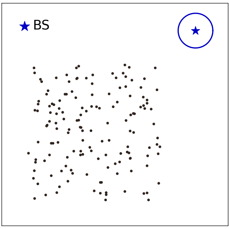
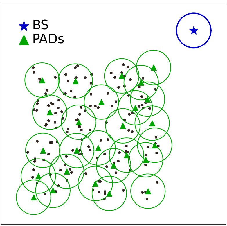
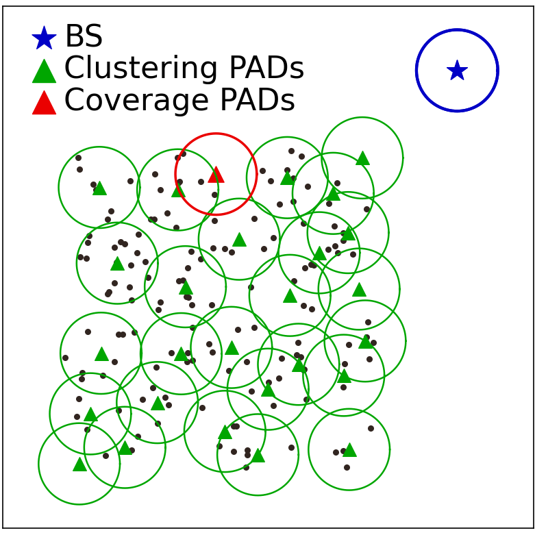
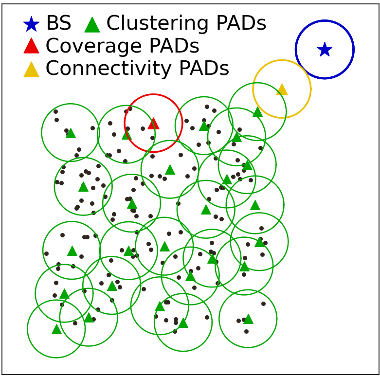
We propose a PAD placement scheme, named CDC&DSC (Clustering-with-double-constraints & Disks-shift-combining), to address the MNDP problem, which can automatically adapt to network scenarios with arbitrary node distribution and arbitrary BS location. The CDC&DSC scheme works in two phases and we propose two algorithms, CDC (Clustering-with-double-constraints) algorithm and DSC (Disks-shift-combining) algorithm, to accomplish the task of each phase separately. The task of phase 1 is to generate the initial solution of the MNDP problem, which we achieve by using the CDC algorithm. In the CDC algorithm, we first cluster all nodes based on geographic locations, then deploy a PAD at the center of each cluster, and then obtain an initial solution to our problem by adding new PADs to satisfy the coverage constraint and the connectivity constraint. The task of phase 2 is to optimize the initial solution from phase 1, which we complete by using the DSC algorithm. In the DSC algorithm, we decrease the number of PADs by combing the PADs based on the principle of triangle circumcircle after trying to shift each PAD to its nearest neighbor. In the rest of this section, we depict the details of the two algorithms one by one.
5.1 CDC Algorithm
The goal of the CDC algorithm is to generate an initial solution to the MNDP problem. Essentially, the output of CDC should be a set of PADs with their coverage disks.
Input:
A sensor node set , a BS
Output:
An initial PAD set
Considering the MNDP problem, we must cover all the nodes with as few PADs as possible. Intuitively, the ideal situation is that each node is covered by one and only one PAD. Furthermore, considering the coverage constraint, the geographical locations of nodes covered by the same PAD should be close. Based on the above considerations, we first use a clustering algorithm to cluster the nodes and deploy a PAD in the center of each cluster. Then we can obtain an initial solution to the MNDP problem by adding some PADs to meet the coverage constraint and the connectivity constraint.
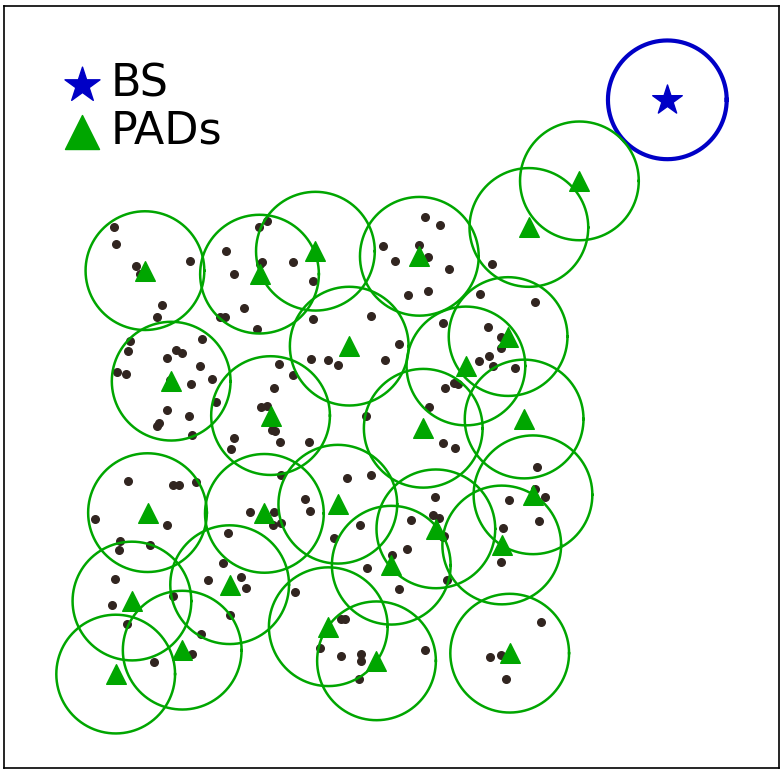
The goal of clustering nodes is to determine a series of locations to place PADs to cover the nodes in the network. The node is surely covered by the BS. Thus, we only cluster the set of nodes . In our case, we use the K-means algorithm to cluster the nodes. One problem with using the K-means algorithm is that we need to determine the parameter . We notice that isolated nodes may appear in the network scenarios since our goal is to be able to handle scenarios with arbitrary node distribution and arbitrary BS locations. The isolated nodes are more difficult to cover than the other nodes. Based on this consideration, we determine the value of by the number of isolated nodes. Let denotes the distance between node and its nearest neighbor node , and is the set of isolate nodes. Besides, we denote as a parameter to adjust . We have
| (13) |
| (14) |
We use the locations of isolate nodes as the initial points of K-means in Fig. 1(b). After clustering, we place a PAD in the center of each cluster and generate a coverage disk for each PAD. Then, we check if all nodes are covered. If some nodes are not covered, we select the node farthest from its nearest neighbor node and deploy a PAD in its place . We repeat the process until all nodes are covered. For the connectivity constraint, we construct a connected graph from the BS with edge length not exceeding . The PADs closest to the graph are added to the connected graph in turn. If the distance between a PAD to be added and the nearest vertex in the graph exceeds , a new PAD is generated on the line connecting the PAD to the corresponding vertex at a distance from the vertex, until all PADs are added to the connected graph. The details of the CDC algorithm are shown in algorithm 1.
5.2 Disks-shift-combine
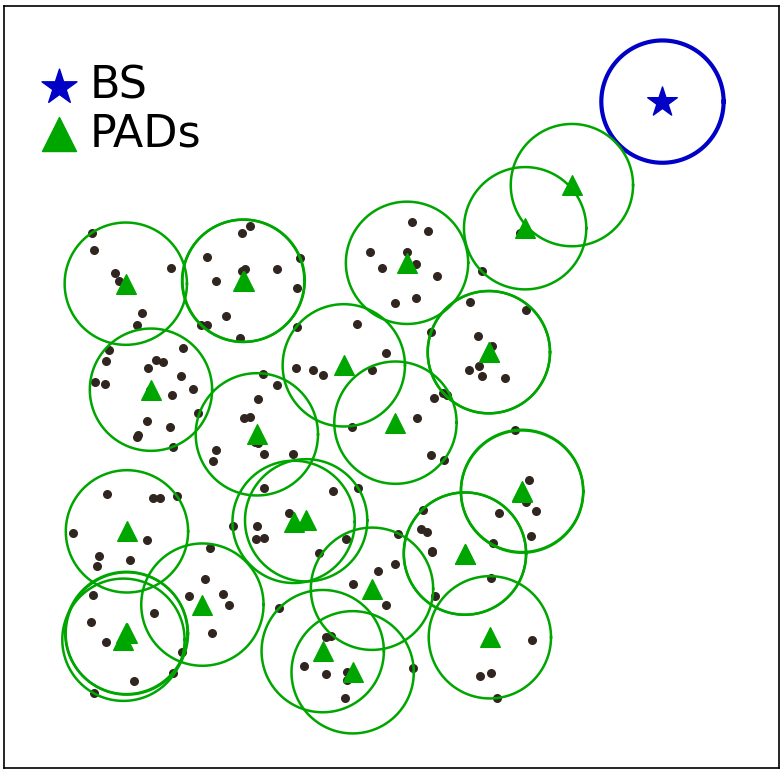
After obtaining a feasible solution , and we decrease the number of PADs in the DSC algorithm. To reduce computational complexity, we first delete some redundant PADs in . The PAD is redundant if the still satisfies two constraints after removing . We can observe some redundant PADs in Fig. 1(d) and they are deleted in Fig. 2(a).
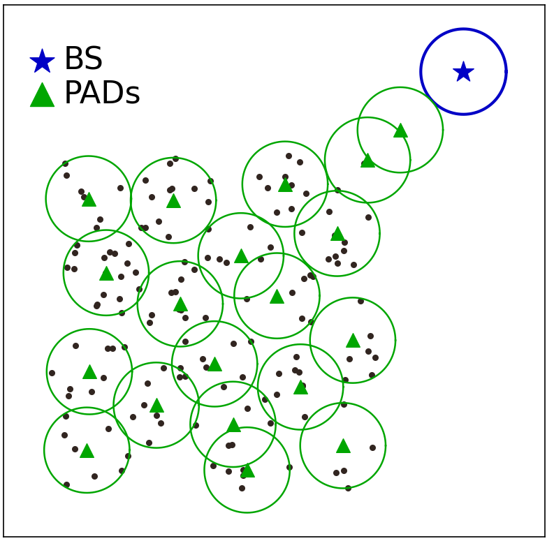
After deleting the redundant PAD, we merge the adjacent PADs to decrease the number of PADs. Before merging the PADs, we first try to reduce the distance between the PADs by a nearest neighbor shift method to facilitate the next merging operation. Let denotes the set of nodes only covered by the PAD . We select the PAD with the minimal to perform the following operations. We first shift the location of the PAD with the step length toward its nearest neighbor PAD, then generate a coverage disk at the new location, and then check the coverage constraint and the connectivity constraint. If these two constraints are not satisfied, we delete the new location and begin the other loop for the next PAD. Otherwise, we continue to shift this PAD with the step length . We repeat the above process until all PADs have been shifted. Fig. 2(b) shows the result of shifting. After all the PADs are shifted, we try to re-delete the redundant PADs.
After the shifting operations, we can merge the adjacent PADs to get the minimal set of PADs. We attempt to perform the adjacent PAD merge operation in the following way. For each neighbor PAD of , , we calculate the discrete point set , which is the set of nodes only covered by and :
| (15) |
We select the two most distant nodes in and try to merge and to a new PAD at the midpoint between these two selected nodes. If the merging result can not meet both the coverage constraint and the connectivity constraint, we check whether there is an enclosing circle of radius covering . If there is, we merge and to a new PAD at the center of this enclosing circle b16 ; b17 . We repeat the above steps until all the have been tried the merging operation. We show the details in algorithm 2.
We give a demonstration on how the DSC algorithm works in Fig. 2. Fig. 2(a) presents the result of deleting redundant operation on the deployment result in Fig. 1(d), while Fig. 2(b) and Fig. 2(c) show the results of shifting operations and merging operations, respectively.
Input:
An initial PAD set
Output:
A final PAD set
6 Simulation Result
In this section, we evaluate the performance of the proposed scheme. To illuminate the effectiveness of our proposed scheme, we compare it with the four algorithms in b13 . To the best of our knowledge, the work in b13 and our scheme are the only two works investigating the PADs deployment in a UAV-based WRSN.
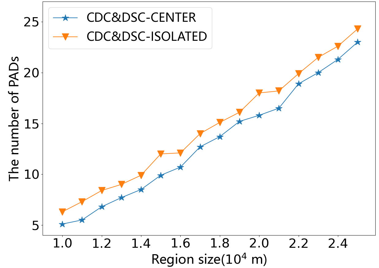
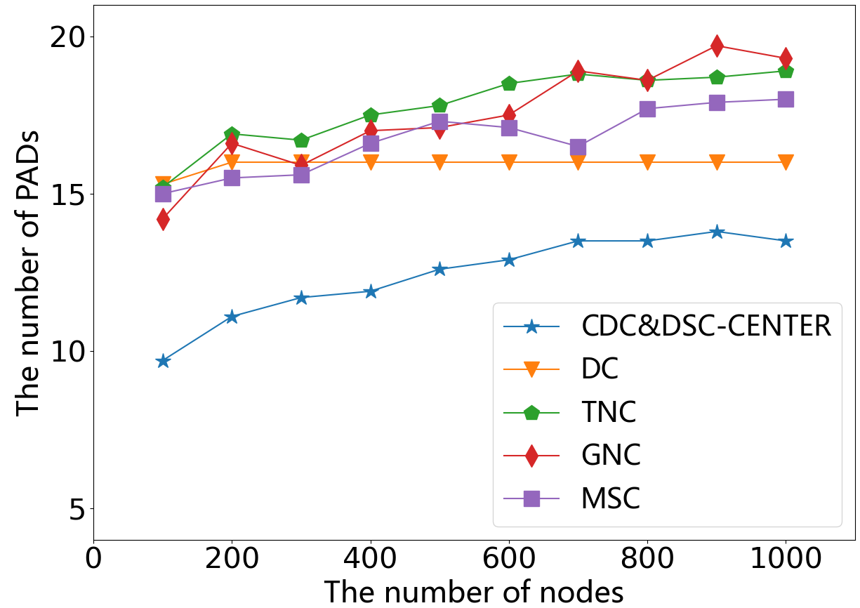
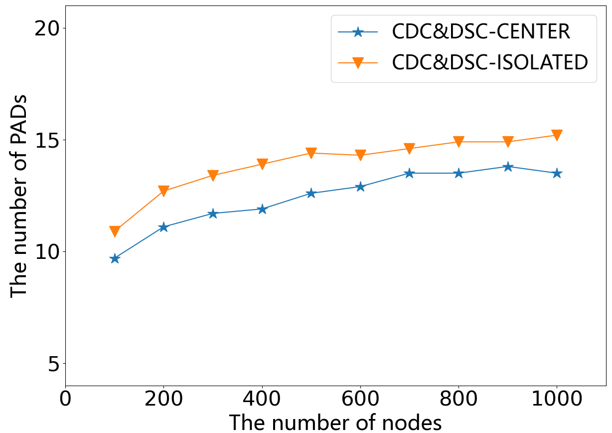
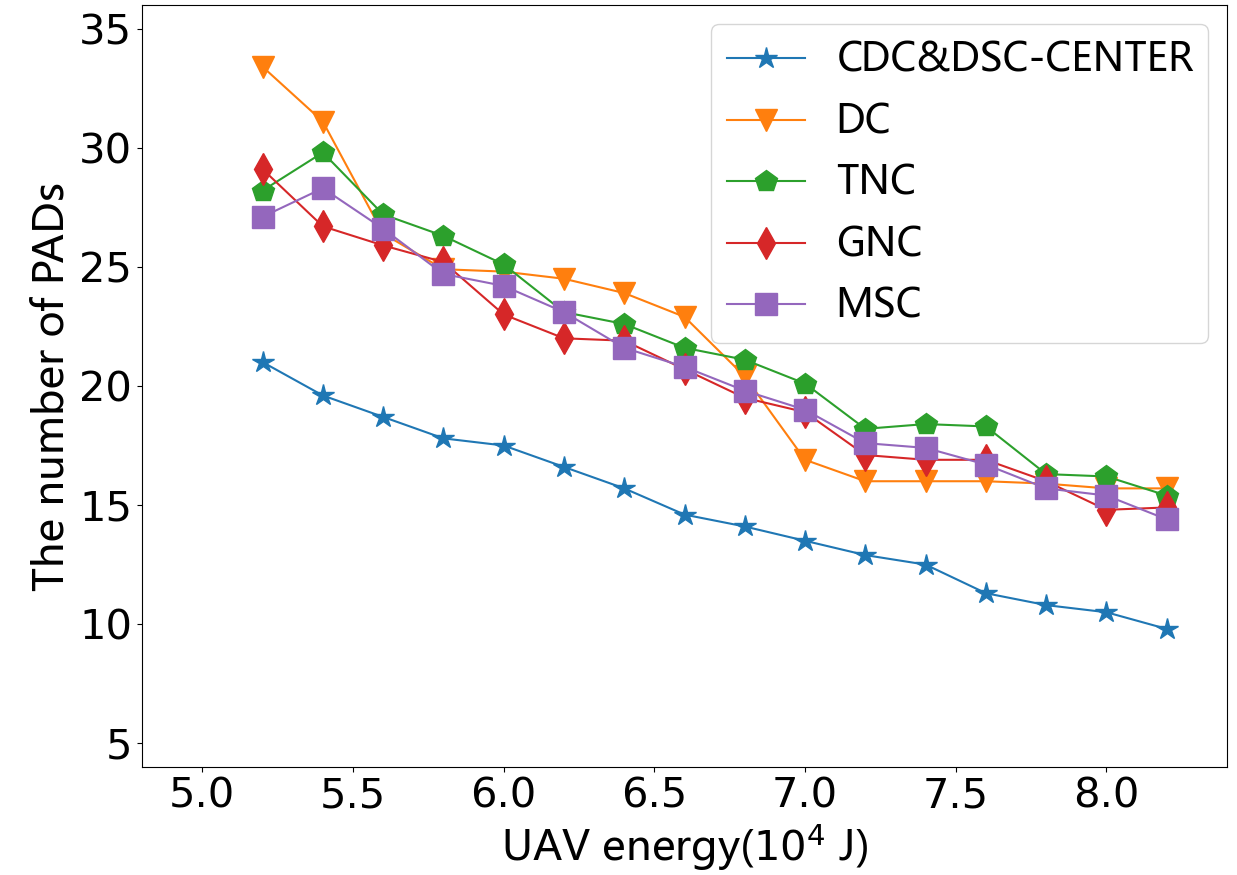
We carry out four groups of simulations by varying the size of the network region, the number of nodes, the battery capacity of UAV, and the different node distributions, respectively. To verify the adaptability of the proposed scheme to arbitrary BS locations, we transform two BS locations for each group of simulations: the BS-center scenario, where the BS is surrounded by nodes in the center of the network area, and the BS-isolated scenario, where the BS is outside of the network area and the distance to any node is greater than . Due to the algorithms in b13 cannot work in the scenarios of BS-isolated, we compare our scheme with the four algorithms in the BS-center scenario first and then we compare the performance of our scheme in these two scenarios. We take the average results with 10 sets of data to smooth data in each simulation. The default parameters are shown in Table 1.
| Parameters | Value |
|---|---|
| Region size() | 16000 |
| Number of nodes | 200 |
| 7.8 | |
| 30 | |
| 0.3 | |
| BS location | [8000,8000](central) |
| [20000,20000](isolated) |
6.1 The impacts of the region size
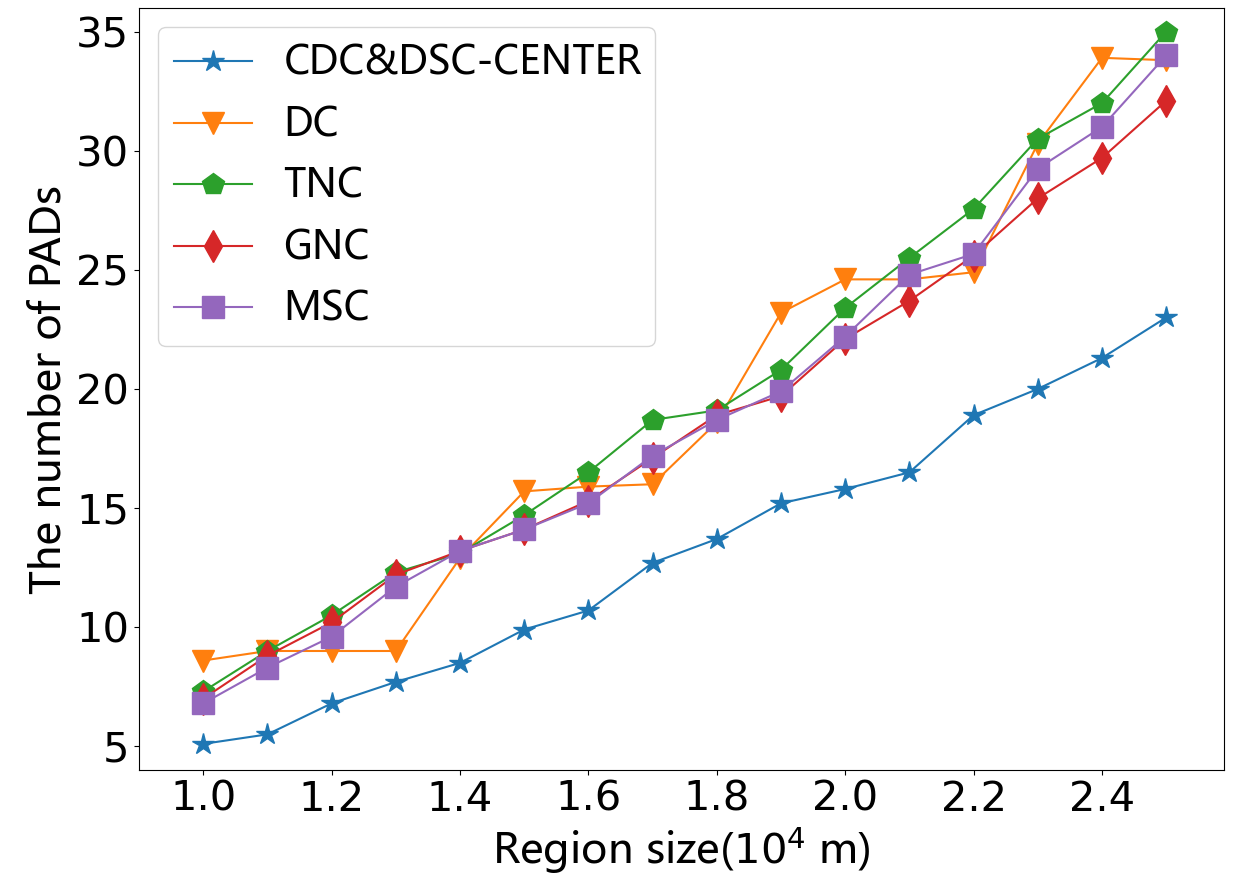
Fig. 3 presents the simulation results with varying the size of the network region from to . As expected, for all the algorithms, the number of PADs increases as the size of the network region increases. The reason is that as the network size increases, the distance between nodes increases and more PADs are needed to satisfy the coverage constraint. Fig. 3 shows the BS-isolated scenario always requires more PADs than the BS-center scenario. This is because we need to introduce additional PADs to ensure the connectivity constraint in the BS-isolated scenario. It is important to notice from Fig. 3 that the number of PADs deployed by the proposed scheme is always less than four comparison algorithms, and this advantage continues to grow as the network area increases. This changing trend demonstrates the proposed algorithm has advantages in WRSNs with large network region.
6.2 The impacts of the number of nodes
Fig. 4 depicts the simulation results for varying the number of nodes from to . Comparing with Fig. 3, for all the algorithms, the number of PADs is growing slowly as the node number increases in Fig. 4. It is because the PAD deployment problem is essentially a coverage problem, and the number of PADs depends mainly on the coverage radius of the UAV and the size of the network, while it is less affected by the node density. We also notice that the result of the DC algorithm is always 16 when the node number is over 200. One reason is that the DC algorithm always deploys PADs at the center of each cell after celling the network area and then removes the PADs of the cells with no node. Therefore, when the node density is above the threshold value (all cells have nodes), the result of the DC algorithm will not change. The other approaches determine the locations of PADs from the geographic distributions of nodes, so an increase in node density has a slight effect on their results. Still, we can find that the proposed scheme achieves the best performance in Fig. 4. From Fig. 4, we conclude the similar conclusion within Fig. 3. In the BS-isolated scenario, it takes more PADs to ensure the connectivity constraint than in the BS-center scenario.
6.3 The impacts of the battery capacity of UAV
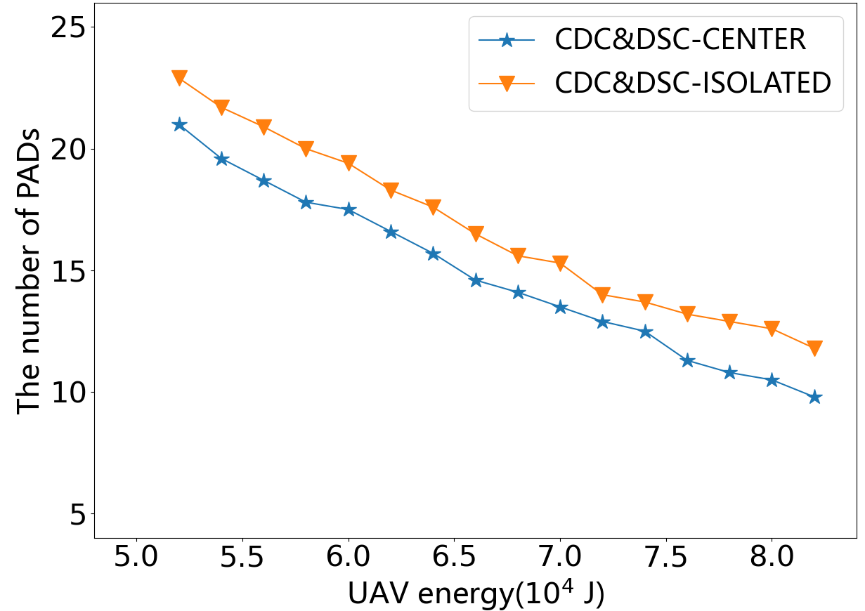
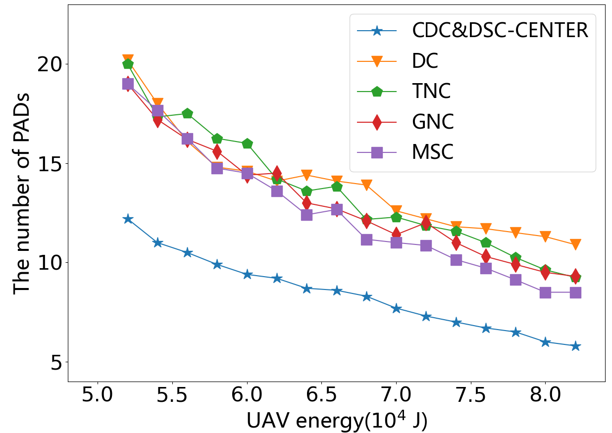
We also vary the battery capacity of UAV with results presented in Fig. 5. As the battery capacity increases, the number of PADs of all the schemes decreases. The more energy the UAV itself carries, the larger and become. As a result, each PAD has a larger coverage disk, while the connectivity constraint can be satisfied by fewer PADs. The number of PADs in the proposed scheme is obviously 8 to 10 less than all the comparing algorithms. One reason is that the four comparison algorithms always deploy PADs at fixed locations: TNC, GNC, and MSC deploy PADs at nodal locations, while DC deploys PADs at the centers of some cells after celling the network area. Also, none of the four comparison algorithms attempted to merge adjacent PADs.
6.4 The impacts of the triple Gaussian Mixture distribution
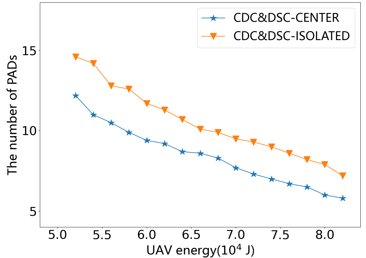
We further carry out some simulations to verify the adaptability of the proposed scheme to the arbitrary node distribution. We build a scenario with 300 nodes with a triple Gaussian Mixture distribution. We divide 300 nodes into three groups and each group of one hundred nodes is deployed according to a Gaussian distribution. Since the expectation and variance of the three Gaussian distributions are random, the deployment areas of the three groups of nodes may or may not overlap. We vary the battery capacity of UAV in this scenario with results presented in Fig. 6. For the DC approach and our proposed scheme, the results are the average of 10 sets of data. Since the TNC, GNC, and MSC may not work in the scenarios with three groups of nodes isolate with each other, for these algorithms we only counted the results in scenarios where they could work. According to Fig. 6, the number of PADs decreases as the battery capacity increases. The reason is the same as the previous simulation results in Fig. 5. Comparing Fig. 5, the numbers of PADs in this type of scenario are much smaller than in the scenarios with a uniform distribution of nodes. It can be explained as follows, when the mixed Gaussian distribution is obeyed, the nodes are clustered more closely than when the uniform distribution is obeyed. Consequently, the actual network area size becomes smaller, the performances of all the approaches are improved in this type of scenario. Our proposed algorithm still achieves the minimum number of PADs in this type of scenario.
In general, the CDCDSC algorithm outperforms all the comparing algorithms. It can adapt to the scenarios with arbitrary node distribution and arbitrary BS location.
7 Conclution
After years of research, the introduction of PADs for UAV energy replenishment has become a promising approach to improve the performance of UAV-based WRSNs. In this paper, we investigated the PADs deployment problem for the UAV-based WRSNs. We proposed a novel PADs deployment scheme, named CDC&DSC, to adapt to the scenarios with arbitrary node distribution and arbitrary BS location. We proposed the CDC algorithm to generate an initial deployment of PADs, and then proposed the DSC algorithm to optimize this initial solution in an attempt to merge adjacent PADs and remove redundant PADs by shifting the locations of PADs. Finally, we compared the proposed scheme with four existing PADs deployment approaches through simulations. The results showed that our proposed scheme outperforms the existing methods in all aspects. However, our proposed algorithm deals with the deployment of PADs only from the perspective of minimizing the number of PADs, without considering the charging scheduling. In the future, we are planning to solve the PADs deployment problem to improve the global charging efficiency by taking the charging demand of nodes and the scheduling of UAVs into account.
References
- (1) Ren, X., W. Liang, and W. Xu. Maximizing charging throughput in rechargeable sensor networks. In 2014 23rd International Conference on Computer Communication and Networks (ICCCN). 2014, pp. 1–8. 10.1109/ICCCN.2014.6911792.
- (2) Guo, S., C. Wang, and Y. Yang. Joint Mobile Data Gathering and Energy Provisioning in Wireless Rechargeable Sensor Networks. IEEE Transactions on Mobile Computing, Vol. 13, No. 12, 2014, pp. 2836–2852. 10.1109/TMC.2014.2307332.
- (3) Han, G., J. Wu, H. Wang, M. Guizani, and W. Zhang. A Multi-Charger Cooperative Energy Provision Algorithm Based on Density Clustering in the Industrial Internet of Things. IEEE Internet of Things Journal, Vol. 6, No. 5, 2019, pp. 9165–9174.
- (4) Lin, C., C. Guo, H. Dai, L. Wang, and G. Wu. Near Optimal Charging Scheduling for 3-D Wireless Rechargeable Sensor Networks with Energy Constraints. In 2019 IEEE 39th International Conference on Distributed Computing Systems (ICDCS). 2019, pp. 624–633. 10.1109/ICDCS.2019.00068.
- (5) Wu, P., F. Xiao, C. Sha, H. Huang, and L. Sun. Trajectory Optimization for UAVs’Efficient Charging in Wireless Rechargeable Sensor Networks. IEEE Transactions on Vehicular Technology, Vol. 69, No. 4, 2020, pp. 4207–4220. 10.1109/TVT.2020.2969220.
- (6) Baek, J., S. I. Han, and Y. Han. Optimal UAV Route in Wireless Charging Sensor Networks. IEEE Internet of Things Journal, Vol. 7, No. 2, 2020, pp. 1327–1335. 10.1109/JIOT.2019.2954530.
- (7) Cetinkaya, O. and G. V. Merrett. Efficient Deployment of UAV-powered Sensors for Optimal Coverage and Connectivity. In 2020 IEEE Wireless Communications and Networking Conference (WCNC). 2020, pp. 1–6. 10.1109/WCNC45663.2020.9120738.
- (8) Simic, M., C. Bil, and V. Vojisavljevic. Investigation in Wireless Power Transmission for UAV Charging. Procedia Computer Science, Vol. 60, No. 1, 2015, pp. 1846–1855.
- (9) Choi, C. H., H. J. Jang, S. G. Lim, H. C. Lim, S. H. Cho, and I. Gaponov. Automatic wireless drone charging station creating essential environment for continuous drone operation. In 2016 International Conference on Control, Automation and Information Sciences (ICCAIS). 2016, pp. 132–136. 10.1109/ICCAIS.2016.7822448.
- (10) Costea, I. M. and V. Pleşca. Automatic battery charging system for electric powered drones. In 2018 IEEE 24th International Symposium for Design and Technology in Electronic Packaging(SIITME). 2018, pp. 377–381. 10.1109/SIITME.2018.8599208.
- (11) Campi, T., S. Cruciani, M. Feliziani, and F. Maradei. High efficiency and lightweight wireless charging system for drone batteries. In 2017 AEIT International Annual Conference. 2017, pp. 1–6. 10.23919/AEIT.2017.8240539.
- (12) Cai, C., J. Wang, H. Nie, P. Zhang, Z. Lin, and Y. G. Zhou. Effective-Configuration WPT Systems for Drones Charging Area Extension Featuring Quasi-Uniform Magnetic Coupling. IEEE Transactions on Transportation Electrification, Vol. 6, No. 3, 2020, pp. 920–934. 10.1109/TTE.2020.2995733.
- (13) Chen, J., C. W. Yu, and W. Ouyang. Efficient Wireless Charging Pad Deployment in Wireless Rechargeable Sensor Networks. IEEE Access, Vol. 8, 2020, pp. 39056–39077. 10.1109/ACCESS.2020.2975635.
- (14) Griffin, B. and C. Detweiler. Resonant wireless power transfer to ground sensors from a UAV. In 2012 IEEE International Conference on Robotics and Automation. 2012, pp. 2660–2665. 10.1109/ICRA.2012.6225205.
- (15) Zeng, Y., J. Xu, and R. Zhang. Energy Minimization for Wireless Communication With Rotary-Wing UAV. IEEE Transactions on Wireless Communications, Vol. 18, No. 4, 2019, pp. 2329–2345. 10.1109/TWC.2019.2902559.
- (16) Frank, N. and N. Richard. A fast deterministic smallest enclosing disk approximation algorithm. Information Processing Letters, Vol. 93, No. 6, 2005, pp. 263–268.
- (17) Wan, P., Y. Cheng, and B. Wu. An Algorithm to Optimize Deployment of Charging Base Stations for WRSN. EURASIP Journal on Wireless Communications and Networking, Vol. 63, 2019, pp. 1–9.