Nanoindentation of single crystalline Mo: Atomistic defect nucleation and thermomechanical stability
Abstract
The mechanical responses of single crystalline Body-Centered Cubic (BCC) metals, such as molybdenum (Mo), outperform other metals at high temperatures, so much so that they are considered as excellent candidates for applications under extreme conditions, such as the divertor of fusion reactors. The excellent thermomechanical stability of molybdenum at high temperatures (400-1000oC) has also been detected through nanoindentation, pointing towards connections to emergent local dislocation mechanisms related to defect nucleation. In this work, we carry out a computational study of the effects of high temperature on the mechanical deformation properties of single crystalline Mo under nanoindentation. Molecular dynamics (MD) simulations of spherical nanoindentation are performed at two indenter tip diameters and crystalline sample orientations [100], [110], and [111], for the temperature range of 10-1000K. We investigate how the increase of temperature influences the nanoindentation process, modifying dislocation densities, mechanisms, atomic displacements and also, hardness, in agreement with reported experimental measurements. Our results suggest that the characteristic formation and high-temperature stability of [001] dislocation junctions in Mo during nanoindentation, in contrast to other BCC metals, may be the cause of the persistent thermomechanical stability of Mo.
keywords:
Nanoindentation , dislocation loops , Molybdenum1 Introduction
The development of novel technology in aerospace, electronic, medical and energy industries requires the use of materials that can mechanically sustain extreme operating conditions, that may include, among others, high temperature and irradiation. In these environments, it is characteristic that BCC metals, such as tungsten and molybdenum, display excellent features. For example, molybdenum is a material with persistent high temperature hardness and strength, as well as high resistance to corrosion [1, 2, 3], and good thermodynamic properties at high pressure [4, 5, 6]. These properties have promoted molybdenum to be used for building a plasma wall component and fusion divertors over other materials [2, 7, 8, 9, 10]. Nevertheless, compared to face-centered cubic (FCC) metals, the plastic behavior (strength, hardness) of BCC metals is quite complex and remains relatively unexplored, with only few nanoindentation studies addressing dislocation mechanisms in pure BCC single crystals [11, 12, 13, 14, 15, 16, 17]. In particular, it has remained poorly understood why some BCC metals display high thermomechanical stability at high temperatures, and persistence of mechanical properties. Especially, Mo single crystals display persistent hardness at high temperatures [18], a feature that is absent in other BCC single-crystalline metals [17]. While the emergence of such thermomechanical stability has previously been attributed to grain-boundary effects [19], in single crystals the effects shall be connected to fundamental dislocation mechanisms. Furthermore, the observation of corresponding thermomechanical stability in nanohardness, through nanoindentation, suggests the connection to defect nucleation [18]. Here, we investigate the mechanical nanoindentation response of Mo to a spherical indenter, at high temperatures, by using MD simulations, and considering [100], [110], and [111] orientations in a temperature range of 10-1000K, and a repulsive imaginary indenter. Our results suggest that junction formation is prevalent in Mo, especially compared to other BCC metals, such as Ta [17] or W [14, 20, 21, 22].
Temperature effects on plasticity of Mo have been shown to span a range of properties, from yield stress to the resistance to fatigue and creep to restrict progressive deformation [19, 23]. Ab initio simulations have been used for the study beyond the point of maximum elastic deformation [24] and coupled atomistic continuum methods have been extensively used to simulate nanoindentation of Mo, concluding that plasticity mechanisms are consistent with typical mechanisms observed in other BCC metals [19, 25, 26]. In the context of BCC metals, studies of nanoindentation in Ta [27] have shown that nanocontact plasticity in BCC is driven by the nucleation and propagation of twin and stacking fault bands, and Remington et al. showed that a cowboy-like ”lasso” mechanism is responsible for the formation of prismatic loops [28]. In addition, the investigation of the temperature and loading-rate dependence of the first pop-in load in nanoindentation of Ta has provided further light to collective dislocation mechanisms [29]. A complementary dimension has been added through uniaxial compression studies of micropillars that showed the importance of the relative sample orientation and also, the key role of screw dislocations at room temperature in BCC metals (Ta, Mo and Fe), in contrast to FCC (Cu) [30, 31]. Even though plasticity mechanisms in micropillar compression may be different than nanoindentation and quite complex [32], the key role of screw dislocations in driving plasticity in BCC metals cannot be understated. In this context, Molybdenum and its alloys are tougher than W facilitating the manufacturing process for the fusion machine components [9], where the mechanical properties such hardness and elastic modulus can be measured by nanoindentation [33, 34, 19, 18, 35] enabling to analyze thermal activated mechanisms that change the mechanical properties of the material. However, nanoindentation experiments at elevated temperatures have several technical issues that need to be considered, e.g. thermal drift that can be caused by a temperature mismatch between the tip and the sample [36].
A possible way to investigate features of nanomechanical properties and their causal relation to atomistic defect mechanisms at high temperatures, is through atomistic simulations. Molecular dynamics (MD) simulations have been extensively pursued in the past, showing to be a powerful tool towards emulating nanoindentation experiments, albeit at the nanoscale of few nanometers, while providing atomistic insights to the mechanical response of indented samples [26, 27, 29, 37, 38, 39]. The major advantage of MD simulations at high temperatures is the ability to investigate the thermomechanical stability of dislocation nucleation and propagation, as well as stacking faults and twin boundaries, and how they contribute to the increase or decrease of hardness [40]. These atomistic simulations can also be applied to study the anisotropy of mechanical properties of materials at different temperatures which is a helpful tool to guide experiments where technical limits and costs are important [41, 40].
In this work, we perform MD simulations to emulate nanoindentation of crystalline molybdenum by considering [100], [110], and [111] orientations in a temperature range of 10-800K, with a spherical indenter. In Section 2 we describe the details of the numerical simulations. In Section 3, the atomistic insights of indentation processes in crystalline Mo sample are presented, where we track hardness as function of temperature, in conjunction to dislocation loop formation, local displacements’ magnitude, and dislocation densities, showing the effects of sample temperatures on nanoindentation mechanisms. Agreement with experimental measurements is reported and discussed, in connection to dislocation junction formation. Finally, in section 4, we provide concluding remarks.
2 Computational methods
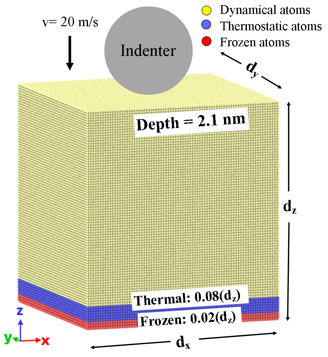
In order to perform MD simulations of nanoindentation, the prepared sample is divided into three sections on the direction for setting up boundary conditions, as shown in Fig. 1. In addition, we consider 5 nm vacuum section on the top, above the material sample and also the two lowest bottom layers are kept frozen ( 0.02dz) to assure stability of the Mo atoms when nanoindentation is performed. A thermostatic region above the already defined frozen one is considered to dissipate the generated heat during nanoindentation, with a thickness of 0.08dz. The rest of the layers are defined as a region with dynamical atoms, in which the atoms interact as the indenter tip modifies the surface structure of the Mo sample. The dimensions of the simulation box, for the simulations performed in this work, are mentioned in Table 1.
In the dynamical atoms region, the numerical modeling of a nanoindentation process starts by defining the simulation box as a pristine crystalline Mo sample based on a body-centered cubic cell. Then, we apply molecular dynamics through a NVE statistical thermodynamic ensemble where the velocity Verlet algorithm is implemented in the Large-scale Atomic/ Molecular Massively Parallel Simulator (LAMMPS) software [38, 42] Periodic boundary conditions are set on the and axes to simulate an infinite surface, while the orientation contains a fixed bottom boundary and a free top boundary in all MD simulations.
| Orientation | Size (dx, dy, dz) [nm] | Atoms |
|---|---|---|
| 25.18 25.81 26.90 | 1 128 320 | |
| 24.80 25.44 28.71 | 1 171 170 | |
| 26.21 25.81 30.10 | 1 313 352 |
The indenter tip is considered as a non-atomic repulsive imaginary (RI) rigid sphere with a force potential defined as: where eV/Å3 (37.8 GPa) is the force constant, and is the position of the center of the tip as a function of time, with radius . Here, with and as the center of the surface sample on the xy plane, the nm is the initial gap between the surface and the intender tip moves with a speed = 20 m/s. The loading and unloading processes are defined by considering the direction of the velocity as negative and positive, respectively. Each process is performed for 125 ps with a time step of fs. The maximum indentation depth is chosen to 2.1 nm to avoid the influence of boundary layers in the dynamical atoms region.
Our MD simulations are focused on standard nanoindentation simulations of body-centered cubic (BCC) molybdenum in the , , and crystal orientations. For this, we use the LAMMPS software and utilize the embedded-atom method (EAM) potential [37, 43, 44]. The Mo samples are initially energy optimized at 0 K by the conjugate gradient algorithm with energy tolerance of 10-6 eV. The samples are then thermalized for 100 ps with a Langevin thermostat to temperatures of 10, 300, 600, 800 K and 1000K with the time constant of 100 fs. This is done until the system reaches a homogeneous sample temperature and pressure profile. A final step is performed by relaxing the prepared sample for 10 ps to dissipate artificial heat. The elastic constants, Cij, bulk modulus, and Poisson’s ratio for different temperatures are computed by using the EAM potential for a small BCC Mo sample of 1 nm in the direction. The obtained values are presented in Table 2.
| Cij | MD | Exp. | MD | MD | MD |
|---|---|---|---|---|---|
| 0 K | 300 K | 600 K | 800 K | ||
| C11 | 464.7 | 464 | 417.8 | 354.1 | 321.6 |
| C22 | 464.7 | 464 | 409.3 | 340.5 | 307.6 |
| C33 | 464.7 | 464 | 415.3 | 347.9 | 312.9 |
| C12 | 161.5 | 159 | 163.2 | 163.2 | 162.5 |
| C13 | 161.5 | 159 | 163.3 | 164.7 | 165.1 |
| C23 | 161.5 | 159 | 162.2 | 160.5 | 159.8 |
| C44 | 108.9 | 109 | 108.4 | 108.3 | 108.3 |
| C55 | 108.9 | 109 | 107.0 | 104.2 | 102.4 |
| C66 | 108.9 | 109 | 106.1 | 102.1 | 99.5 |
| Bulk Mod. | 262.59 | 250 | 246.6 | 224.40 | 212.96 |
| Poisson R. | 0.26 | 0.29 | 0.28 | 0.32 | 0.34 |
2.1 Calculation of mechanical properties
The hardness of the indented sample is calculated by computing the curve with the Oliver and Pharr method [45], following the fitting curve to the unloading process curve as:
| (1) |
with is the indentation load; is the indentation depth and is the residual depth after the whole indentation process; and and are fitting parameters. Thus, the nanoindentation hardness can be computed as: where is the maximum indentation load at the maximum indentation depth, is the projected contact area with as the indenter tip radius and . Here is a factor related to the spherical indenter shape, and unloading stiffness is calculated as
| (2) |
The Young’s module is computed as:
| (3) |
where and are the Poisson’s ratio of the Mo sample and indenter, respectively. is the Young’s modulus of the spherical indenter that is considered to be infinitely large, and the effective elastic modulus with for a spherical indenter shape. In this way, the nano-hardness of the indented samples can be calculated at different temperatures and indenter tip sizes.
The deformation of the indented Mo samples may be estimated through the use of the stress tensor of the -th atom during the nanoindentation process. The von Mises stress of the -th atom is calculated as follows:
| (4) |
The six components of are obtained from the output data of the MD simulations.
For the shear dependence of nanoindentation, atomic strains are computed through the distance difference, , between the the -th nearest neighbors of the -th atom of the pristine and indented samples. Followed by defining the Lagrangian strain matrix of the -th atom as [39]:
| (6) |
Thus, the shear invariant of the -th atom is computed as:
| (7) |
This approach is implemented in OVITO [46].
3 Results
3.1 Temperature Dependence of nano-hardness for , , and orientations.
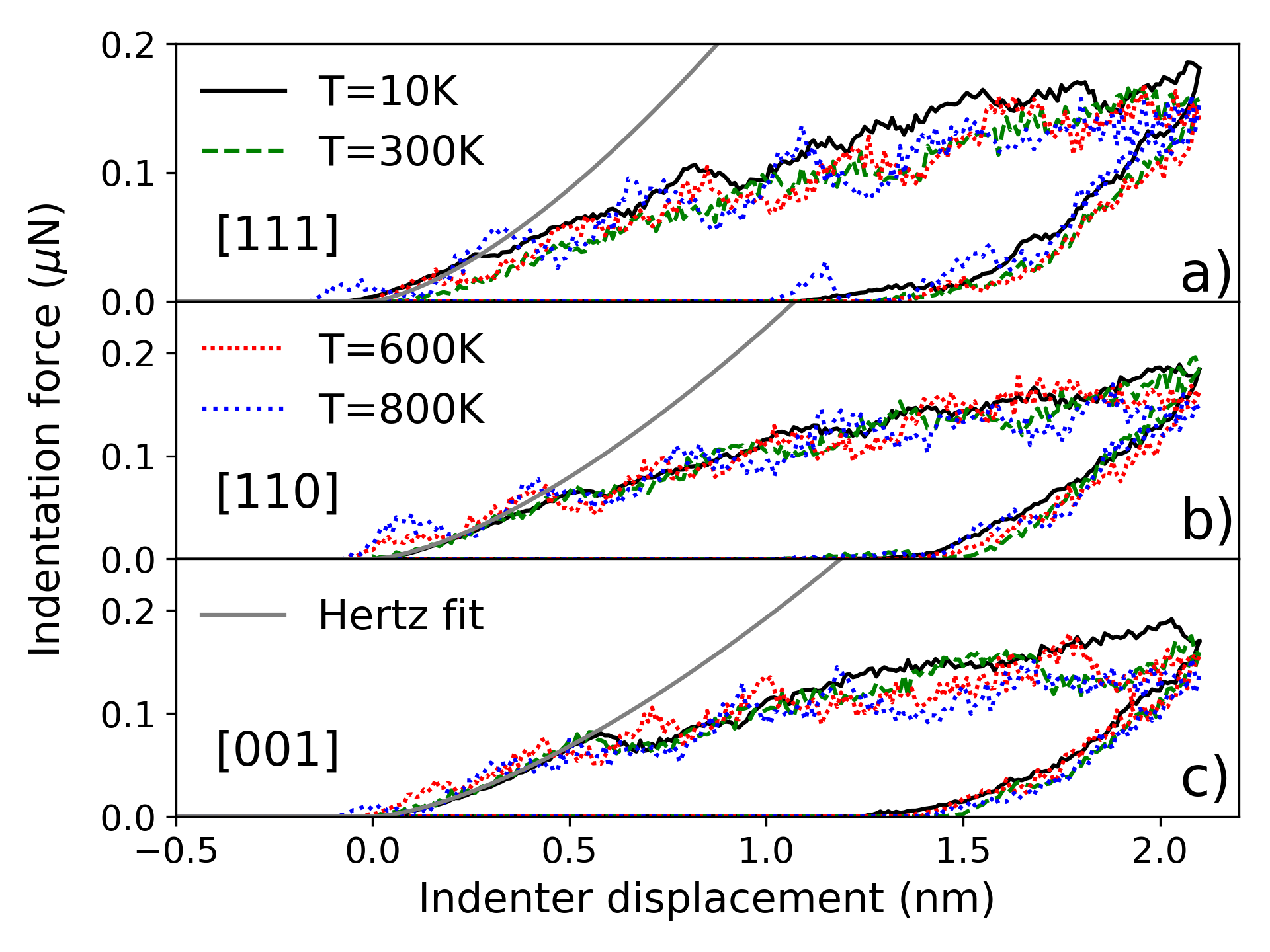
The loading and unloading processes in nanoindentation of crystalline Mo oriented in , , and are recorded, and the P-h curves are presented in Fig. 2 for a tip radius of 3 nm (for larger tip radius (6 nm), please see Sec. 3.2), at the different sample temperatures. At contact, all studied samples follow classical Hertz theory where the sphere-flat surface contact solution is expressed as
| (8) |
where are indexes related to the crystal orientation, is the Poisson’s ratio, is the indenter radius, is the indenter displacement, and is the elastic modulus calculated as
| (9) | |||||
with as the components of the compliance tensor and , , and are the direction cosines of the crystal orientation. Obtaining a elastic moduli of GPa, = 287.02 GPa, and = 305.94 GPa at the lowest temperature. It is observed that the deviation of MD simulations from the Hertzian elasticity solution at 10K takes place at different deformations, greater than 0.57 0.05 nm for , 0.5 0.05 nm for , and 0.26 0.05 for the crystal orientation, consistent with experimental findings of orientation dependence in crystal plasticity of BCC metals [21, 27, 30].
| Orient. | [001] | [110] | [111] | |||||||||
|---|---|---|---|---|---|---|---|---|---|---|---|---|
| Temp. [K] | 10 | 300 | 600 | 800 | 10 | 300 | 600 | 800 | 10 | 300 | 600 | 800 |
| Pmax [N] | 0.170 | 0.160 | 0.155 | 0.136 | 0.184 | 0.182 | 0.161 | 0.148 | 0.181 | 0.160 | 0.158 | 0.152 |
| AC [nm2] | 23.85 | 24.06 | 23.83 | 23.97 | 23.41 | 24.15 | 23.81 | 23.96 | 23.72 | 24.09 | 24.00 | 23.33 |
| S[N/m] | 432.5 | 461.76 | 387.87 | 424.42 | 369.3 | 504.54 | 403.27 | 301.29 | 416.9 | 456.27 | 399.8 | 317.81 |
| H | 6.92 | 6.59 | 6.28 | 6.38 | 7.23 | 6.84 | 6.60 | 4.57 | 7.12 | 6.40 | 5.89 | 6.43 |
| 73.17 | 76.87 | 63.20 | 67.94 | 63.06 | 84.83 | 65.75 | 48.25 | 70.74 | 76.81 | 64.91 | 51.57 | |
| -5.63 | -6.23 | -9.08 | -10.79 | -6.67 | -7.20 | -10.09 | -14.31 | -5.16 | -5.27 | -8.38 | -12.39 | |
| 4.81 | 3.76 | 3.71 | 6.79 | 4.20 | 3.06 | 4.01 | 6.71 | 2.86 | 3.12 | 3.72 | 7.00 | |
| 2.51 | 2.06 | 2.06 | 3.42 | 2.29 | 1.65 | 2.25 | 3.61 | 1.49 | 1.79 | 1.92 | 3.57 | |
| 7.13 | 6.63 | 6.50 | 5.71 | 7.86 | 7.53 | 6.76 | 6.18 | 7.63 | 6.64 | 6.58 | 6.51 | |
| 0.35 | 0.31 | 0.32 | 0.59 | 0.29 | 0.22 | 0.33 | 0.51 | 0.19 | 0.27 | 0.29 | 0.55 | |
We notice that the residual depth after indentation is h 0.1 nm for [100] and [110] orientations, while a value of h is found for the [111] orientation at 10 K. When the sample is thermalized to 600K, the elastic section of the P-h curve starts to oscillate due to the deformation of the surface shifting the residual depth after unloading process. This effect is more relevant at a temperature of 800K, where the Mo atoms interact with the spherical indenter before touching the surface. We also notice that the indentation force at maximum depth, decreases as a function of the temperature, regardless of crystal orientations, in good agreement with reported results for Ta [27]. The plastic region of the curves show more oscillations at higher temperatures due to the thermal motion of dynamical atoms region in the sample.
The resulting P-h curve for the unloading process can be fitted to the Hertz elastic solution according to Eq. 1 to compute mechanical properties of the Mo sample like Hardness and Young’s modulus, that should in principle compare to experimental data at comparable depths. In Tab. 3, we report the following values that are computed at the maximum indentation depth: maximum force, Pmax in N, the projected contact area, AC in nm2, the stiffness, S in units of N/m, and Hardness and Young modulus in units of GPa. As well as the hydrostatic stress ; the total value of von Mises and Tresca stresses; the mean pressure is computed as the instance force divided by the contact area, Ac, namely Fmax/AC. We also verify the relation factor between the mean pressure and the maximum shear stress underneath the indenter, where the classical Hertz theory suggests a value of 0.465 (See Table 3). Our MD simulations corroborates that this factor depends on the atomic scale and sample temperature, as reported in the literature [47].
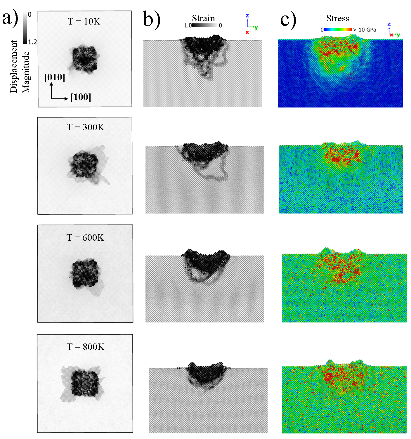
In order to provide more insights about the effect of temperature in the mechanical response of Mo samples, we analyze atomic strain information. This analysis provides information about the topography of surface deformation and pileup that can be compared to experimental results. In Fig. 3a), we present the distribution of atomic displacement magnitude of damage of indented Mo samples in a top view for the orientation with different sample temperatures, as an example. Noticing that pileups are found along the in-plane slip directions {101} and {10-1}, this region is gradually enlarged by increasing the temperature due to atomic thermal motion, commonly identified in BCC investigations [27].
In Fig. 3b) and c), we report the atomic shear strain and von Mises stress for different temperatures and the orientation. The sample is slid to the half in the axis to visualize the atomic distribution of the shear strain and von Mises stress by coloring Mo atoms according to their values. The increase of temperature suppresses propagation of dislocation lines, and suppresses the size of the plastic zone. It is also noticed that the strain and stress underneath the indenter increases as long as Mo atoms start moving faster due to thermal motion, which is also noted in the broader stress distribution. The analysis applied to the and crystal orientations are presented in the supplementary material (A). It is worth pointing out that the formation of a prismatic loop is observed on the [111] orientation at high temperatures, possibly suggesting that mechanisms shown at low temperatures [28] are relevant also at high temperatures.

It is interesting to analyze the atomic structure at the maximum indentation depth, where the computation and visualization of the dislocation structure are done by using the Dislocation Extraction Analysis (DXA) tool [46]. The output data provides the total length of dislocation lines and loops and their corresponding Burgers vectors. In Fig. 4a), we present the formation of dislocation loops at the maximum nanoindentation depth in the crystal orientation at a depth of 2.1nm. In Fig. 4b), the visualization of the deformed contact surface after unloading is shown, displaying the formation of pile-ups. We also include the information for the formation of shape and Burgers vector (depicted as blue arrows) of the (colored in green), (colored in magenta), and (colored in blue) dislocations. The total length of the dislocations, LT, is also noted, pointing to a dependence on the sample temperature after nanoindentation. In Fig. 4b) we display the remained dislocations after unloading process where the effect of temperature is observed through the quick adsorption of dislocations on the sample surface. The effect of crystal orientation is reported in the supplementary material (A), where it is also shown that dislocations disappear after nanoindentation loads are removed at high temperatures.
3.2 Effect of the indenter tip radius
| Orient. | [001] | [110] | [111] | |||||||||
|---|---|---|---|---|---|---|---|---|---|---|---|---|
| Temp. [K] | 10 | 300 | 600 | 800 | 10 | 300 | 600 | 800 | 10 | 300 | 600 | 800 |
| Pmax [N] | 0.440 | 0.430 | 0.403 | 0.361 | 0.430 | 0.382 | 0.423 | 0.373 | 0.399 | 0.359 | 0.331 | 0.361 |
| AC [nm2] | 54.86 | 55.65 | 58.01 | 57.28 | 46.29 | 51.84 | 52.37 | 55.14 | 54.93 | 55.13 | 55.93 | 55.55 |
| S[N/m] | 781.37 | 849.71 | 1018.02 | 952.41 | 595.94 | 825.21 | 891.47 | 939.05 | 709.76 | 789.44 | 765.44 | 834.71 |
| H | 7.70 | 7.65 | 6.72 | 6.97 | 12.21 | 11.77 | 11.27 | 8.97 | 8.15 | 7.55 | 7.35 | 7.61 |
| 87.17 | 93.03 | 106.32 | 109.06 | 72.38 | 96.71 | 97.99 | 99.12 | 80.27 | 86.83 | 89.58 | 87.78 | |
| -15.66 | -17.12 | -19.63 | -19.90 | -11.38 | -14.82 | -17.07 | -21.49 | -11.62 | -9.95 | -14.33 | -12.38 | |
| 7.58 | 4.54 | 1.26 | 4.05 | 8.16 | 5.69 | 2.49 | 4.53 | 8.33 | 5.71 | 1.71 | 7.00 | |
| 3.92 | 2.45 | 0.70 | 2.14 | 4.27 | 3.16 | 1.42 | 2.47 | 4.36 | 2.92 | 0.99 | 3.58 | |
| 8.02 | 7.72 | 6.94 | 6.30 | 9.29 | 8.40 | 8.08 | 6.76 | 7.47 | 6.45 | 6.99 | 6.50 | |
| 0.49 | 0.32 | 0.1 | 0.34 | 0.46 | 0.38 | 0.18 | 0.36 | 0.58 | 0.45 | 0.17 | 0.55 | |
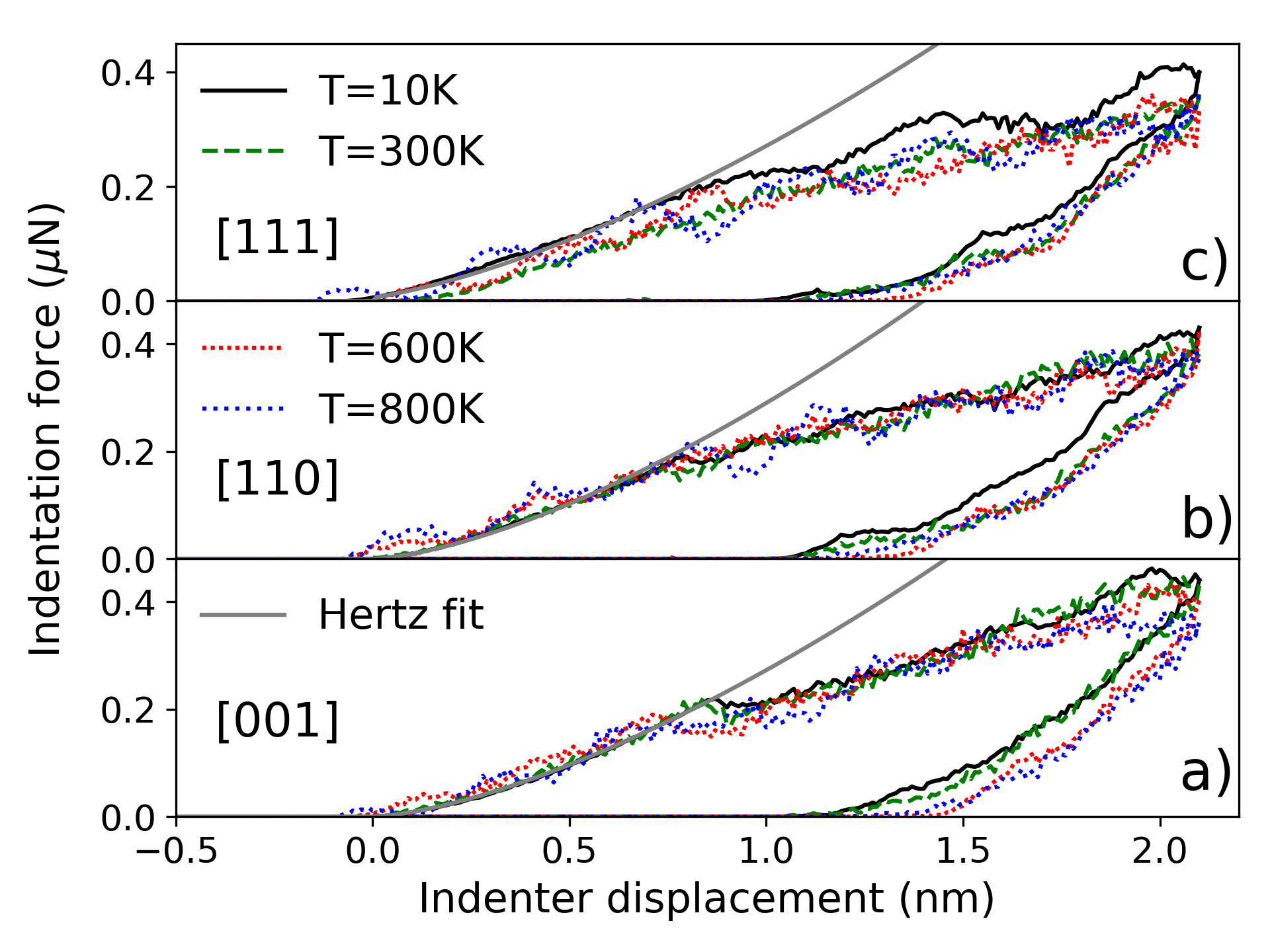
The spherical-tip nanoindentation studied in this work may resemble Berkovich nanoindentation at ultra-short depths (nm), however, in this regime, the mechanical response may display strong size effects [48], naturally influencing relevant plasticity mechanisms. The effects of the indenter tip size on the observed nanoindentation plasticity mechanisms of Mo samples, are tracked by considering a larger tip radius of 6 nm, followed by performing MD simulations under the same numerical environment as smaller tip ones. In Fig. 5, we present the P-h curve of the nanoindetation process at different sample temperatures and crystal orientations. The corresponding classical Hertz solution (Eq. 8) is superposed to show the effects of the temperature during the interaction of the surface and the sphere. For this case, the MD simulations deviated from the Hertz elastic solution at 10K at 0.86 0.05 nm for , 0.78 0.05 nm for , and 0.37 0.05 for the crystal orientation, also displaying very strong orientation dependence, as expected for BCC plasticity mechanisms [30]. Note that the first pop-in load is independent of the indenter size, leading to the [001] crystal orientation to reach the maximum indentation force and the [111] one to the lowest value regardless the sample temperature. Nevertheless, the pop-in load decreases from the [110] to [111] and [001] at temperatures above 600 K. We also note that the residual depth is 1.1 0.05 nm for the three crystal orientations at 10K. This value increases as function of the sample temperature. In Tab. 4, we report the obtained hardness , Young modulus , stiffness , and yield stresses as function of temperature for reference and further discussion.
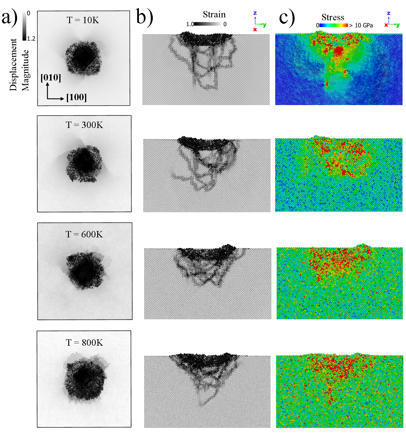
In Fig. 6, we present the resultant atomic configuration of Mo samples after loading, as function of temperature for the [100] orientation, as an example. The analysis for the indented of Mo samples at [110] and [111] orientations are presented in the supplementary material of this work (A). In Fig. 6a), we report the distribution of the atomic displacement magnitude in a scale of 0 to 1.2 nm. Here, the pileup pattern at 10 K shows expectedly that the maximum shear stress is observed for the {101} and {10-1} slip systems, as also reported for single crystalline Mo samples experimentally studied by Plummet et al. [18]. This stress pattern is maintained at higher temperatures. Fig. 6 shows the atomic strain and von Mises stress 6b) and c), respectively. While the thermally induced plastic zone reduction, observed for the smaller tip, is not present for the larger tip, there are close similarities to the atomic strain profiles and maxima as well as the temperature dependence of the von Mises stress.
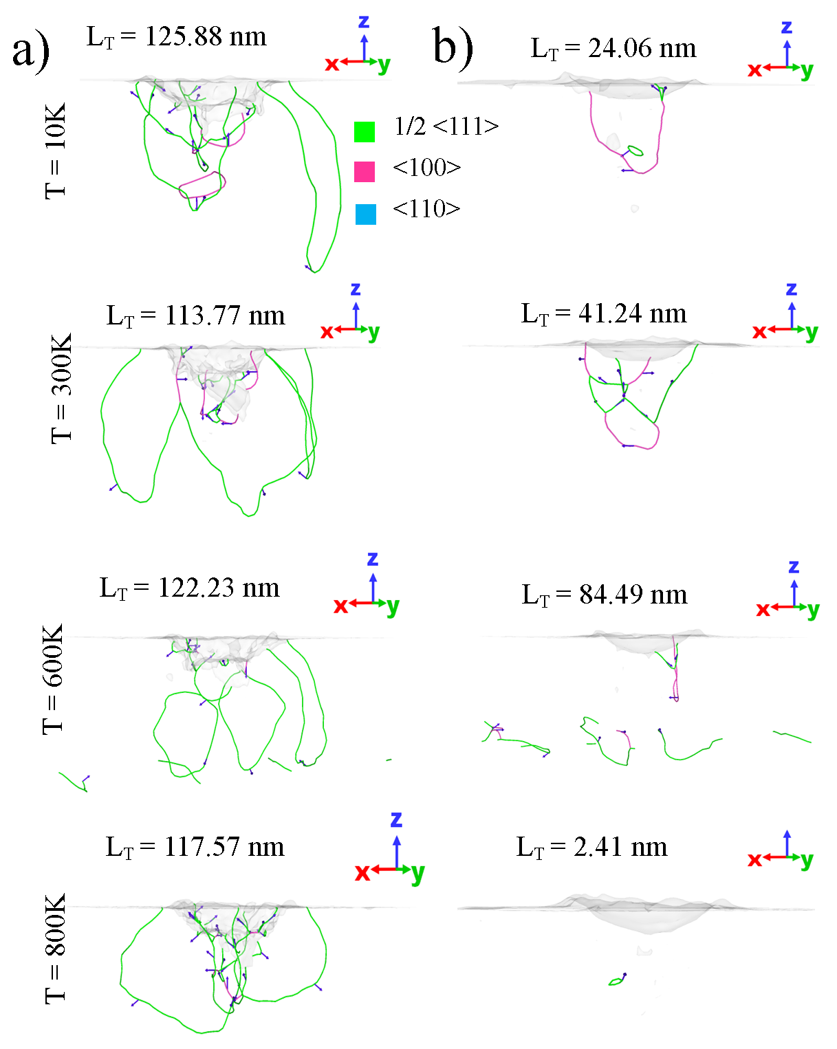
In Fig. 7, the plastic zone is characterized in two limits: a) at the maximum indentation depth and also, b) after nanoindentation, and it is characterized through the identification of the types of emerging dislocations at different temperatures. During loading, it is observed that the total length of the dislocations is larger than those reported for a smaller indenter regardless of the sample temperature. Evidence of the ‘lasso‘ mechanism [28] exists at all temperatures, suggesting that the main dislocation nucleation mechanism remains analogous to other BCC metals. After unloading, there is evidence of remaining dislocations that provide clues for the hardening mechanisms at high temperatures. Only at 800 K the dislocation nucleation appears to be overwhelmed by thermal atomic motions that drive dislocations towards surface deposition events. The formation of prismatic loops is favorable for large radius indenters at all temperatures (up to 800K), justifying prior studies for other BCC metals.
3.3 MD insights for experiments in Mo
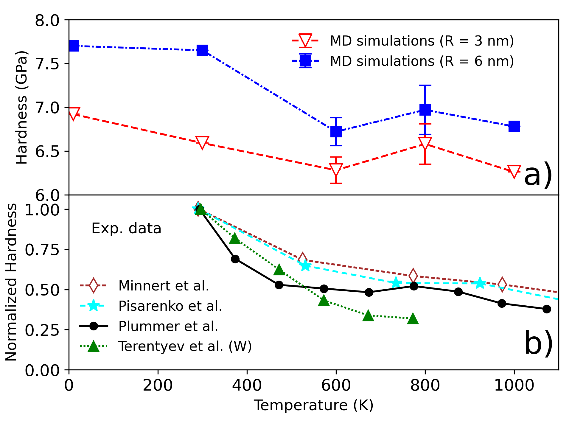
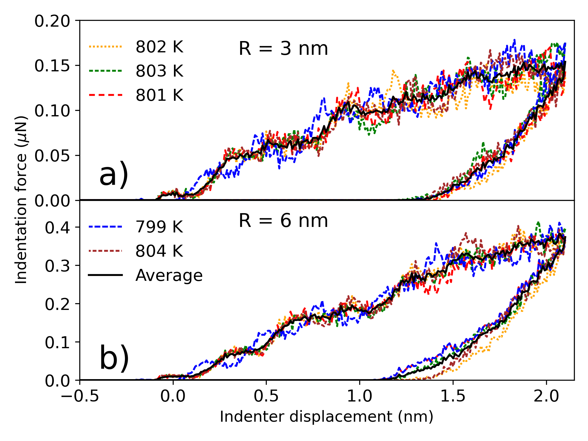
In Fig. 8 we present the temperature dependence of hardness of Mo on the [001] orientation at 2.1 nm depth and its comparison to experimental data reported by Plummer et al. [18] for the same crystal orientation. We also include experimental data of Mo by Pisarenko et al. [22] and Minnert et al. [35] for polycrystalline Mo samples as reference. We finally include the experimental measurements by Terentyev et al. [20] for W showing a monotonically decrease of hardness as a function of the temperature. The high temperature behavior resembles the one observed in the experiments [18, 22, 35] where the material hardness reaches a saturation at a temperature of 700 K. This is encouraging, given that the experimentally studied depths were much larger, pointing towards maintaining the same trend in thermal effects, despite the strong size effects. This finding is consistent with successfully modified Nix-Gao models that suggest that the emergence of thermal effects arises only through the statistically stored dislocation density in the plastic zone and in a power law form, which is then linearly added to the geometrically necessary dislocation density [19, 49]. The considered error bars in hardness are obtained through additional MD simulations and computed as is the standard deviation, the average of the MD results, and , the total number of MD simulations performed. As an example, Fig. 9 shows the P-h curves of the nanoindenation of the sample at 800 K for a radius of 3nm in a) and 6nm in b) where the increase of the hardness material is observed.
The thermomechanical stability seen in the hardness data (see Fig. 8) is strongly correlated with the total dislocation length and dislocation propagation during nanoindentation. In Fig. 10a) we show the dislocation density as function of the indenter displacement for different temperatures by considering the 3nm-sized indenter tip. The results for the bigger indenter tip are also presented in the supplementary material (A). By using the approximations of a spherical plastic zone, the dislocation density, h is computed as
| (10) |
where LT is the dislocation length, and is the largest distance of a dislocation measured from the indentation displacement, considering a hemispherical geometry. From our MD simulations, we observe (see Fig. 10a) that the nucleation of and dislocations is responsible for the hardness saturation at high temperatures. Moreover, as shown in the inset of Fig. 10b), the [001] dislocation segments are actually, dislocation junctions between 1/2[1-1-1] and 1/2[-11-1] dislocations, as well as their symmetry equivalents. The number of this type of junctions found in our MD simulations as a function of the indenter displacement is presented in Fig. 10b) and its schematic is displayed in the inset. Here Burgers vectors are depicted as blue arrows and dislocation lines are shown by green and pink lines for 1/2[111] and [001], respectively. In the supplementary material, we also show a visualization of dislocation nucleation as function of time for the [001] Mo sample at different temperatures to demonstrate the generic formation of [001] junctions (A). These junctions are proliferating at high temperatures, and are highly stable at the maximum load. [001] junctions have been long considered as a major hardening mechanism in BCC metals [50] that may explain typical strengthening [51].

Thus, we suggest that [001] junctions may be responsible for the persistent thermomechanical stability of Mo single crystals. Thermally stable [001] junctions are found to be responsible for increasing material nanohardness, and in contrast, this kind of junction formation has been shown to be unstable in other BCC metals, such as W and Ta [20, 27]. We conclude that the combination of kinetics and energetics in molybdenum leads to an increased stability of [001] junctions that are well known to play key role in strengthening effects of BCC metals [50].
4 Concluding remarks
In this work, we performed MD simulations to investigate the thermal stability of the mechanical response of crystalline molybdenum during nanoindentation, investigating the effects of crystal orientation, temperature and dislocation mechanisms. We characterized the nanoindentation process in molybdenum, in connection to experimental findings, and through tracking strain accumulation and dislocation mechanisms for several temperatures, sample orientations and indenter tips. Our simulation results suggest that crystal plasticity in nanoindentation of molybdenum follows closely known defect nucleation mechanisms for BCC metals, albeit with distinct differences in the formation and thermal stability of [001] junctions, that are observed and quantified as function of temperature during loading. The observed [001] junction formation in molybdenum was shown to be responsible for increasing the nano-hardness of molybdenum, by correlating it to the dislocation density of each dislocation type. In contrast, such stable junction formation is barely observed during nanoindentation of W and Ta [20, 27]. Given that [001] junctions are well known culprits of hardening in BCC metals [50], we believe that persistent high-temperature hardness in Mo may be attributed to [001] junction formation. Therefore, the simulation results presented in this work suggest that there may be fundamental dislocation-based kinetic reasons for molybdenum being a good, low-maintenance material candidate for applications in extreme environmental conditions, over other BCC metals.
Acknowledgments
We would like to thank Łukasz Kurpaska for inspiring conversations. We acknowledge support from the European Union Horizon 2020 research and innovation program under grant agreement no. 857470 and from the European Regional Development Fund via the Foundation for Polish Science International Research Agenda PLUS program grant No. MAB PLUS/2018/8. We acknowledge the computational resources provided by the High Performance Cluster at the National Centre for Nuclear Research in Poland, and also the Seawulf institutional cluster at the Institute for Advanced Computational Science in Stony Brook University.
Appendix A Supplementary material
We provide the analysis of the indented Mo sample for the [110] and [111] at different temperatures and indenter size. As well as the visualization of the dislocation loops at the maximum indentation depth and after unloading process.
References
- [1] Xue K M, Wang Z, Wang X, Zhou Y F and Li P 2020 Materials Science and Technology 0 1–9
- [2] Lee S, Edalati K and Horita Z 2010 Materials Transactions 51 1072–1079
- [3] Hollang L, Brunner D and Seeger A 2001 Materials Science and Engineering: A 319-321 233–236
- [4] Litasov K D, Dorogokupets P I, Ohtani E, Fei Y, Shatskiy A, Sharygin I S, Gavryushkin P N, Rashchenko S V, Seryotkin Y V, Higo Y, Funakoshi K, Chanyshev A D and Lobanov S S 2013 Journal of Applied Physics 113 093507
- [5] Ragan III C E, Silbert M G and Diven B C 1977 Journal of Applied Physics 48 2860–2870
- [6] Cieszykowska I, Janiak T, Barcikowski T et al. 2017 Applied Radiation and Isotopes 124 124–131 ISSN 0969-8043
- [7] Li P, Lin Q, Wang X, Tian Y and Xue K M 2018 International Journal of Refractory Metals and Hard Materials 72 367–372
- [8] Kumar A, Eyre B L and Christian J W 1980 Proceedings of the Royal Society of London. A. Mathematical and Physical Sciences 370 431–458
- [9] Budd M 1990 Journal of Nuclear Materials 170 129–133
- [10] The Divertor https://www.iter.org/mach/divertor accessed: 15/2/2021
- [11] Smith R, Christopher D, Kenny S D, Richter A and Wolf B 2003 Physical Review B 67 245405
- [12] Durst K, Backes B, Franke O and Göken M 2006 Acta Materialia 54 2547–2555
- [13] Stelmashenko N, Walls M, Brown L and Milman Y V 1993 Acta Metallurgica et Materialia 41 2855–2865
- [14] Syed Asif S and Pethica J 1997 Philosophical Magazine A 76 1105–1118
- [15] Bahr D F, Kramer D E and Gerberich W 1998 Acta materialia 46 3605
- [16] Kramer D, Yoder K and Gerberich W 2001 Philosophical Magazine A 81 2033–2058
- [17] Biener M M, Biener J, Hodge A M and Hamza A V 2007 Physical Review B 76 165422
- [18] Plummer K P 2021 The Temperature Dependence of Plasticity in Molybdenum PhD dissertation University of Oxford
- [19] Voyiadjis G Z, Almasri A H and Park T 2010 Mechanics Research Communications 37 307–314
- [20] Terentyev D, Xiao X, Lemeshko S, Hangen U and Zhurkin E 2020 International Journal of Refractory Metals and Hard Materials 89 105222
- [21] Beake B D and Goel S 2018 International Journal of Refractory Metals and Hard Materials 75 63–69 ISSN 0263-4368 URL https://www.sciencedirect.com/science/article/pii/S026343681830060X
- [22] Pisarenko G, Borisenko V and Kashtalyan Y 1964 Powder Metall Met Ceram. 1 371
- [23] Braun J, Kaserer L, Stajkovic J, Leitz K H, Tabernig B, Singer P, Leibenguth P, Gspan C, Kestler H and Leichtfried G 2019 International Journal of Refractory Metals and Hard Materials 84 104999
- [24] Luo W, Roundy D, Cohen M L and Morris J W 2002 Phys. Rev. B 66(9) 094110
- [25] Picu R 2000 Journal of Computer-Aided Materials Design 7 77
- [26] Hu J, Li M, Wang W and Li L 2018 Molecular dynamics simulations on nanoindentation experiment of single-layer mos2 circular nanosheets Advanced Mechanical Science and Technology for the Industrial Revolution 4.0 ed Yao L, Zhong S, Kikuta H, Juang J G and Anpo M (Singapore: Springer Singapore) pp 333–339 ISBN 978-981-10-4109-9
- [27] Alcalá J, Dalmau R, Franke O, Biener M, Biener J and Hodge A 2012 Phys. Rev. Lett. 109(7) 075502 URL https://link.aps.org/doi/10.1103/PhysRevLett.109.075502
- [28] Remington T, Ruestes C J, Bringa E M, Remington B A, Lu C, Kad B and Meyers M A 2014 Acta Materialia 78 378–393
- [29] Sato Y, Shinzato S, Ohmura T and Ogata S 2019 International Journal of Plasticity 121 280–292 URL https://www.sciencedirect.com/science/article/pii/S0749641919302335
- [30] Kaufmann D, Schneider A S, Mönig R, Volkert C A and Kraft O 2013 International Journal of Plasticity 49 145–151 URL https://www.sciencedirect.com/science/article/pii/S0749641913000740
- [31] Kaufmann D, Mönig R, Volkert C A and Kraft O 2011 International Journal of Plasticity 27 470–478 URL https://www.sciencedirect.com/science/article/pii/S0749641910001130
- [32] Papanikolaou S, Cui Y and Ghoniem N 2017 Modelling and Simulation in Materials Science and Engineering 26 013001
- [33] Voyiadjis G Z and Yaghoobi M 2017 Crystals 7 321
- [34] Zhao J, Huang P, Xu K, Wang F and Lu T 2018 Thin Solid Films 653 365–370
- [35] Minnert C, Oliver W C and Durst K 2020 Materials & Design 192 108727
- [36] Wheeler J, Armstrong D, Heinz W and Schwaiger R 2015 Current Opinion in Solid State and Materials Science 19 354–366
- [37] Domínguez-Gutiérrez F J, Byggmästar J, Nordlund K, Djurabekova F and von Toussaint U 2021 Modelling and Simulation in Materials Science and Engineering URL http://iopscience.iop.org/article/10.1088/1361-651X/abf152
- [38] Plimpton S 1995 Journal of Computational Physics 117 1 – 19
- [39] Shimizu F, Ogata S and Li J 2007 Materials Transactions 48 2923–2927
- [40] Lee S, Vaid A, Im J et al. 2020 Nature Communications 11 2367
- [41] Christopher D, Smith R and Richter A 2001 Nanotechnology 12 372–383 URL https://doi.org/10.1088/0957-4484/12/3/328
- [42] Frenkel D and Smit B 2001 Understanding molecular simulation: from algorithms to applications vol 1 (Elsevier) ISBN 0080519989
- [43] Ackland G J and Thetford R 1987 Philosophical Magazine A 56 15–30
- [44] Salonen E, Järvi T, Nordlund K and Keinonen J 2003 Journal of Physics: Condensed Matter 15 5845–5855
- [45] Oliver W and Pharr G 1992 Journal of Materials Research 7 1564–1583
- [46] Stukowski A 2010 Modelling and simulation in materials science and engineering 18 ISSN 0965-0393
- [47] Goel S, Beake B, Chan C W, Haque Faisal N and Dunne N 2015 Materials Science and Engineering: A 627 249–261
- [48] Bolin R, Yavas H, Song H, Hemker K J and Papanikolaou S 2019 Crystals 9 652
- [49] Song H, Yavas H, Van der Giessen E and Papanikolaou S 2019 Journal of the Mechanics and Physics of Solids 123 332–347
- [50] Argon A 2008 Strengthening mechanisms in crystal plasticity vol 4 (Oxford University Press on Demand) ISBN 0198516002
- [51] Sills R B, Bertin N, Aghaei A and Cai W 2018 Phys. Rev. Lett. 121(8) 085501 URL https://link.aps.org/doi/10.1103/PhysRevLett.121.085501
See pages - of supplemental.pdf