Structure, design, and mechanics of a pop-up origami with cuts
Abstract
The rotational erection system (RES) is an origami-based design method for generating a three-dimensional (3D) structure from a planar sheet. Its rotational and translational kinematics are fully encoded in the form of prescribed cuts and folds that imply negative degrees of freedom. Here, we characterize the mechanical properties of a threefold symmetric elastic RES by combining finite element analysis and a physical experiment. We demonstrate that plate bending creates a physical route connecting the two energetically separated configurations, that is, flat and standing states, allowing RES to morph into a 3D shape via a snap-through transition. We quantify the energy barrier for the bistability, and indicate that it is independent of the entire structure’s span, but depends solely on its aspect ratio. We also indicate that the standing RES has a proper structural rigidity and resilience, owing to its unique self-locking mechanism, suggesting its superior load-bearing performance in a range of applications. The present study clarifies the basic actuation mechanism of an origami-based deployable structure extended with chiral patterned cuts, providing a way to use the optimally designed RES in a range of man-made systems.
Introduction – An origami-inspired design enables the creation of a 3D structure from a planar sheet or membrane Demaine et al. (2011); Tachi (2013); Lebée (2015); Schenk and Guest (2013); Silverberg et al. (2014, 2015); Lechenault and Adda-Bedia (2015); Yasuda and Yang (2015); Faber et al. (2018). Because a folded 3D configuration involves self-contact and overlap, while the surface area must be conserved owing to the sheet inextensibility, its lateral extent usually diminishes so that the structure grows vertically. This intrinsic property of origami underlies the prominent foldability of large membranes, which are utilized in a range of natural Kobayashi et al. (1998); Mahadevan and Rica (2005); Py et al. (2007); Harrington et al. (2011); Forbes (1926); Saito et al. (2017) and man-made systems Miura (1985); Bruton et al. (2016); Kuribayashi et al. (2005).
In contrast, kirigami is a design method that makes a paper sheet highly stretchable by periodically introducing free boundaries, that is, cuts and holes Qi et al. (2014); Isobe and Okumura (2016). In a typical kirigami design, a sheet is free of any overlap or self-contact, but is mechanically monostable; its extended state is stable only in the presence of external loading. Thus, it is interesting to create a multi-stable geometric design in which a single flat sheet morphs into a stable 3D structure vertically, without losing its lateral extent. A similar, but more straightforward example can be determined in certain types of pop-up cards and lift-the-flap books. Strategies for forming 3D microstructures for photonics and flexible electronics are also based on similar concepts, which are designed to be actuated by global buckling compression Zhang et al. (2017). Clearly, an elaborate combination of folds and cuts, called, ”ori-kirigami” is a promising method for developing a novel class of shape-shifting materials Nojima and Saito (2006); Saito et al. (2011); Castle et al. (2014); Neville et al. (2016); Holms (2019); Liu et al. (2020).
.
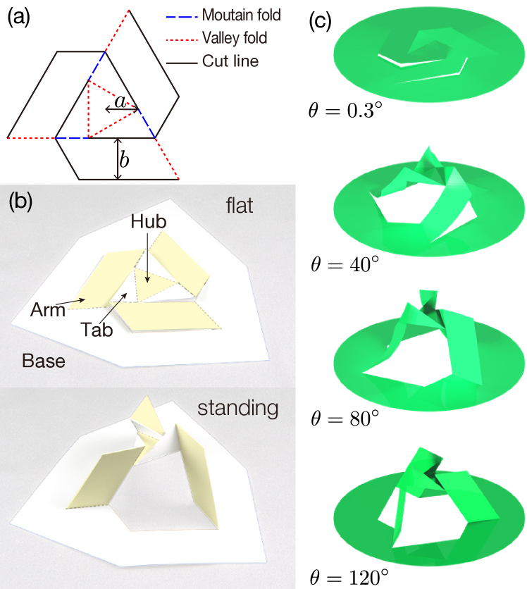
The rotational erection system (RES) developed in Ref. Miyamoto (2014, 2018); Miy provides a unique example of a 2D to 3D transformation without any global edge loading. RES is bistable, and reversibly transforms into a stable 3D structure from a planar sheet with prescribed cuts and fold lines, only by local rotational actuation (Fig. 1) . The 3D standing shape is able to support an external load, as well as its own weight, implying that the RES would be an efficient production method for industrial, artistic, and architectural uses. However, a quantitative investigation of the structure and mechanics of the RES has been unexplored, limiting its practical applications. For example, snapping must be avoided for large-scale architectural purposes, whereas it may be exploited for switching devices, or RES-based energy-absorbing metamaterials. To control and optimize the RES functions, it is crucial to obtain a quantitative and predictive understanding of its energy landscape and geometric scalability ,composed of real physical materials.
To characterize the physical properties of the RES, we first conducted numerical simulations based on finite element analysis (FEA). Compared to the existing origami simulators suitable for quickly grasping the folding behavior of an origami with a given crease pattern Ghassaei et al. (2018), our FEA simulation is physically exact and fully quantitative because it accurately accounts for out-of-plane elastic bending and twisting, as well as in-plane stretching of all the plates constituting the entire RES. Our FEA prediction is then quantitatively verified by a physical experiment using a real RES engineered from a synthetic paper.
Simulation and Experiments Although a variety of multi-stable RES designs exist, we focus on a threefold symmetric RES, as illustrated in Fig. 1 (a) that embodies an essential mechanism common to a family of more complex RES designs com (a). Because the RES morphs into a 3D shape as it is rotated in the vertical direction (defined as the -axis), we characterize its configuration by its height, , and rotational angle Miyamoto (2014). Note that rotational actuation is a key element in the RES design, allowing it to take up additional lengths from a flat, inextensive sheet to grow vertically. Throughout the experiment, we applied an axial external torque to the RES to actuate it without any vertical external force. For our physical RES comprising sufficiently stiff plates (explained below), the effects of gravity on the RES deformations are negligible.
Structurally, RES comprises four parts, which include the base, arms, tabs, and hub. (see Fig. 1). A geometric RES comprising rigid surfaces joined by hinges has a negative degree of freedom (DOF), and is not rigidly foldable. Refer to supplemental material (SM) SM .
Contrary to the prediction solely based on the geometry of the RES design, a shape transition of the RES made from real materials can be readily actuated by twisting the hub with respect to the base. To quantify this unique morphing pathway, we conducted an FEA simulation using the commercial software ABAQUS (Dassault Systems). First, we generated the panels constituting the RES separately, which were then assembled with freely rotatable joints at ridges to build a complete RES. We modeled the base as a thin circular disc with radius , which was attached to another larger disc that mimics the rotatable disc in our experiment, as explained below (Fig. 2 (a)). For the actuation of an entire RES, this outermost disc is gradually rotated by a given step of angle quasi-statically. The equilibrium configuration was obtained by minimizing the elastic energy of a linear isotropic solid using triangular shell elements with geometric nonlinearity. Different values of the Young’s modulus and thickness were examined, with a fixed Poisson’s ratio . The geometric parameters and were set to be equal to those in the experimental model given below. We systematically tested different sets of mesh sizes and types, as well as the base size (in the range of 60-80 mm), and confirmed that the presented results are essentially insensitive to those parameters. We started our computation with a slightly lifted shape from a flat plane, and simulated a complete cycle.
To verify our simulation results, we also conducted a physical experiment. Using our home-built system, we experimentally quantified the axial torque applied to the RES as a function of . The RES with dimensions and was processed at Fuji Toso Kogyo Co., Ltd. using a mm thick YUPO synthetic paper. Because a YUPO paper has a well-defined anisotropy in its bending stiffness owing to the manufacturing process, we conducted an independent mechanical test for YUPO paper, to determine its direction-averaged bending stiffness per unit width of 0.022 Nm SM . This amounts to an effective Young’s modulus of GPa, given the Poisson ratio , which may be valid for the major component of YUPO, that is, polypropylene.) We introduced a half-cut on a crease line that can be regarded as a freely rotatable hinge, compared to the typical forces required to deform the RES panels com (b).
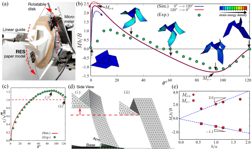
For the torque measurement, we developed an experimental system that comprised two load cells and a rotatable disc onto which an RES paper model was mounted (Fig. 2 (a)). The edge of the base was firmly attached to the disc with an adhesive tape, while the hub plate was attached to a linear translational guide that prohibited any rotation. Thus, the device allows the RES to take an arbitrary rotational angle , without translational constraints. The resulting tangential force necessary to maintain the entire structure at a given was measured using the load cells, from which we deduced the torque by , where mm is the distance between the axis of rotation and the load cell. In the experiment, we investigated the folding (i.e., standing to flat) process only, in which the twisting angle was quasi-statically decreased by , from . The mechanical response of the deployment process (flat to standing) was explored using FEA.
Results– In Fig. 2(b), we plot the rescaled experimental torque , where is the bending modulus per arm of width Audoly and Pomeau (2010), together with the FEA simulation data. Overall, the numerical and experimental data exhibit a similar trend, confirming the validity of the two independent approaches.
We first focus on the region, where the RES is activated from the flat configuration. For an ideal RES studied in the simulation, the s change in shape begins by buckling the three arms. Accordingly, the torque increases discontinuously at , from zero to (Fig. 2 (b)]. Suppose a thin strip of length , thickness , and width , subjected to an external force is applied at one end Audoly and Pomeau (2010). The strip buckles at , where is a numerical prefactor of the order of that depends sensitively on the boundary conditions and geometry of the strip com (c). Assuming threefold symmetry, the buckling torque is . For the arm of RES considered here, , We predict . In Fig. 2 (e), we plot for different values of obtained from the simulations, which confirms that . A deviation is solely observed for , for which a narrow strip assumption is no longer valid. From fitting the data in Fig. 2 (c), we determine that , which is quite a reasonable value as the prefactor of the critical buckling force com (c). In contrast to the simulated RES, the arms of our physical RES are not entirely flat, but have some small permanent curvatures once the RES completes a cycle of shape transformation. Therefore, the physical RES can stand up from the (nearly) flat configuration without any buckling, leading to a smooth torque curve, as well as a reduced peak value, as illustrated in Fig. 2 (b)]. At the maximum torque, the slope becomes negative with increasing , and at , the torque crosses the unstable equilibrium point at which . The RES would jump to another stable configuration at .
We now focus on its behavior around the standing configuration at . To highlight the extent of departure from the standing state, we define as . We observe in Fig. 2 (b)that the magnitude of the torque increases approximately linearly with , for . Interestingly, the height of the RES also increases for this range of [Fig. 2 (c)]. As the hub begins rotation, its arms are bent and simultaneously pushed outwards. Because the arms are tilted with respect to the flat base, the hub must be initially lifted upwards under such combined deformations. Refer to Fig. 2 (d) (i) and (ii). Note that the base slightly leaves the ground during the process. The compliance of the base significantly lowers the risk of the RES damage, particularly in the vicinity of the joints to the base, but is not essential for the kinematics illustrated in Fig. 2 (c)]. As will be discussed later, the unique kinematics that ”locks” its 3D configuration underlies a structural rigidity of the RES investigated below.
Discussion– In Fig. 2 (b), the torque response of the RES was indicated to be fully reversible. However, the energy landscape of the RES around is actually more complicated than expected from Fig. 2 (b). Multiple kinematic pathways are allowed for RES to take on at , most of which lead to an incomplete transformation. For RES to get on the ”right” path at , all the three arms need to buckle towards the same direction synchronously, so that the hub starts moving vertically (either upwards or downwards), keeping its horizontality. If a vertical tensile force is applied to the hub, the up-down symmetry is broken externally, and the synchronized buckling of the three arms is readily induced, which is exactly the way we involuntarily play with the RES manually. Similarly, if the arms have a small initial curvature in a similar direction, this also assists the entire structure in deforming smoothly without elastic instabilities, which is what was observed in the torque measurement experiment. Altogether, a weak distortion intrinsic to structures made of real physical materials, combined with visually guided manipulations manually, can drastically simplify the morphing energy landscape, which then enables the RES to perform as intended, with a stable and reproducible cyclic actuation. This feature will be a fairly generic consequence that is probably valid for a wide class of functionally foldable thin structures, beyond the specific example studied here.
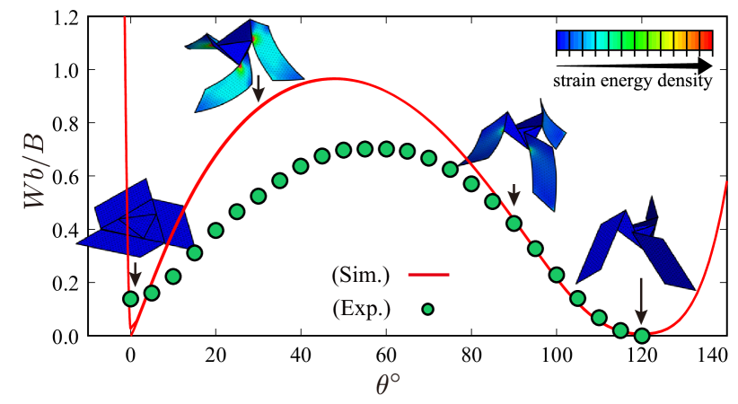
It is now evident that the RES jumps from one stable state to another by bending its three arms elastically. A distributed curvature over the surface of the arm works as a ”virtual crease,” much as for origami with a square-twist pattern Silverberg et al. (2015). The bending energy connects a kinematic pathway between the flat and standing configurations that are otherwise isolated in the configuration space Liu et al. (2018). We can quantify the energy barrier for bistability based on the torque response illustrated in Fig. 2 (b), according to , which is plotted in Fig. 3 as a function of . We reproduce an expected double-well potential with two stable states of a similar energy value. According to the scaling argument given previously, we conclude that the energy barrier for the shape transition, , is defined as
| (1) |
Remarkably, is independent of the entire span of the structure, but solely depends on the ratio , indicating that the bistability of RES is essentially scale-independent. This confirms the validity of the bar-hinge (truss) model, in which a smooth deflection of the arm is substituted with a localized bending stiffness across the ”virtual crease” independent of the length of the arm .
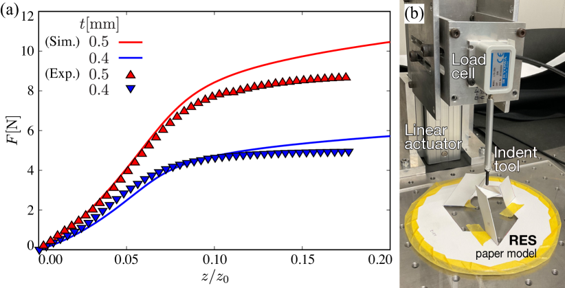
To investigate the mechanical stability of our RES, we conducted a compression test to obtain the load-displacement curves (Fig. 4). We determined that a vertical compression force induces the twisting of the RES beyond , thereby rigidifying the entire structure. Thus, the RES resists the flattening transition, recovering its original configuration immediately the loading is removed, like an ordinary elastic spring Chang et al. (2020). The restoring force increases with an increase in the vertical displacement, where the arms buckle and deflect correspondingly. Actually, the flattening transition (i.e., collapse) of the RES never occurs with compressional loading only. This is understood based on the kinematics of the RES illustrated in Fig. 2 (c), where the RES first has to increase its height to finally reach the flat configuration. It has to be pulled upward first (with its rotation to be allowed freely), and then pushed downward, clearly an impossible mode with a pure compressive load only. The built-in self-locking mechanism is illustrated in Fig. 2 (c), which underlies the structural rigidity of the standing RES in Fig. 4 (a)].
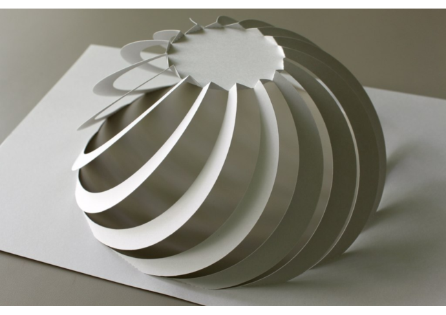
The actuation of a rotationally patterned 3D structure from a planar sheet represents a robust design principle in a range of engineering systems Zhang et al. (2017). A variety of elaborate planar patterns of cuts and folds generate a family of RES with different 3D architectures and topologies, including domes (Fig. 5) and multistage tower-like configurations as well Miyamoto (2014). For more, refer to Miy . These complex designs share similar geometric and mechanical principles that has been revealed for the simplest threefold symmetric model here. The scale-free and tunable nature of RES bistability will be potentially useful in a range of applications, including switching devices, energy-adsorbing mechanical systems, and one-step construction in architectures. Our proof-of-concept study clarifies the basic actuation mechanism of an origami-based deployable structure extended with cuts, and will determine the use of optimally designed RES in a range of artificial systems.
Acknowledgements.
Financial support from JSPS KAKENHI (Grant No. 18K13519 (to H.W.) No. 20K12518 (to Y. M.)) and Grant-in-Aid for JSPS Research Fellow (DC1, No. 19J22381 (to T.Y.)) is acknowledged.References
- Demaine et al. (2011) E. D. Demaine, M. L. Demaine, D. Koschitz, and T. Tachi, in Proc. IABSE-IASS Symp. Taller, Longer, Light. (IABSE-IASS 2011, 2011).
- Tachi (2013) T. Tachi, J. Mech. Des. 135, 111006 (2013).
- Lebée (2015) A. Lebée, Int. J. Space Struct. 30, 55 (2015).
- Schenk and Guest (2013) M. Schenk and S. D. Guest, Proc. Natl. Acad. Sci. USA 110, 3276â3281 (2013).
- Silverberg et al. (2014) J. L. Silverberg, A. A. Evans, L. McLeod, R. C. Hayward, T. Hull, C. D. Santangelo, and I. Cohen, Science 345, 647 (2014).
- Silverberg et al. (2015) J. L. Silverberg, J.-H. Ha, A. A. Evans, B. Liu, T. Hull, C. D. Santangelo, R. J. Lang, R. C. Hayward, and I. Cohen, Nat. Mater. 14, 389 (2015).
- Lechenault and Adda-Bedia (2015) F. Lechenault and M. Adda-Bedia, Phys. Rev. Lett. 115, 235501 (2015).
- Yasuda and Yang (2015) H. Yasuda and J. Yang, Phys. Rev. Lett. 114, 185502 (2015).
- Faber et al. (2018) J. A. Faber, A. F. Arrieta, and A. R. Studart, Science 359, 1386 (2018).
- Kobayashi et al. (1998) H. Kobayashi, B. Kresling, and J. F. V. Vincent, Proc. R. Soc. B 265, 147 (1998).
- Mahadevan and Rica (2005) L. Mahadevan and S. Rica, Science 307, 1740 (2005).
- Py et al. (2007) C. Py, P. Reverdy, L. Doppler, J. Bico, B. Roman, and C. N. Baroud, Phys. Rev. Lett. 98, 156103 (2007).
- Harrington et al. (2011) M. J. Harrington, K. Razghandi, F. Ditsch, L. Guiducci, M. Rueggeberg, J. W. C. Dunlop, P. Fratzl, C. Neinhuis, and I. Burgert, Nat. Commun. 2, 2 (2011).
- Forbes (1926) W. T. M. Forbes, J. NY Entomol. Soc. 24, 91 (1926).
- Saito et al. (2017) K. Saito, S. Nomura, S. Yamamoto, R. Niyama, and Y. Okabe, Proc. Natl. Acad. Sci. USA 114, 5624 (2017).
- Miura (1985) K. Miura, Tech. Rep., Inst. Space Astronaut Sci. (1985).
- Bruton et al. (2016) J. T. Bruton, T. G. Nelson, T. K. Zimmerman, J. D. Fernelius, S. P. Magleby, and L. L. Howell, R. Soc. Open Sci 3, 160429 (2016).
- Kuribayashi et al. (2005) K. Kuribayashi, K. Tsuchiya, Z. You, D. Tomus, M. Umemoto, and M. Sasaki, Mater. Sci. Eng. A 419, 131 (2005).
- Qi et al. (2014) Z. Qi, D. K. Campbell, and H. S. Park, Phys. Rev. B 90, 245437 (2014).
- Isobe and Okumura (2016) M. Isobe and K. Okumura, Sci. Rep. 6, 24758 (2016).
- Zhang et al. (2017) Y. Zhang, F. Zhang, Z. Yan, Q. Ma, X. Li, Y. Huang, and J. A. Rogers, Nat. Rev. Mater. 2, 1 (2017).
- Nojima and Saito (2006) T. Nojima and K. Saito, JSME International Journal A 49, 38 (2006).
- Saito et al. (2011) K. Saito, F. Agnese, and F. Scarpa, J. Int. Mat. Sys. Struct. 22, 935 (2011).
- Castle et al. (2014) T. Castle, Y. Cho, X. Gong, E. Jung, D. M. Sussman, S. Yang, and R. D. Kamien, Phys. Rev. Lett. 113, 245502 (2014).
- Neville et al. (2016) R. M. Neville, F. Scarpa, and A. Pirrera, Sci. Rep. 6, 31067 (2016).
- Holms (2019) D. P. Holms, Curr. Opin. Colloid Interface Sci. 40, 118 (2019).
- Liu et al. (2020) M. Liu, L. Domino, and D. Vella, Soft Matter 16, 7739 (2020).
- Miyamoto (2014) Y. Miyamoto, in Origmai 6: The 6th International Meeting on Origami in Science, Mathematics and Education (2014).
- Miyamoto (2018) Y. Miyamoto, in Origami 7: The 7th International Meeting on Origami in Science, Mathematics and Education (2018).
- (30) Prof. Miyaamoto’s flickr:, https://www.flickr.com/photos/yoshinobu_miyamoto/albums.
- Ghassaei et al. (2018) A. Ghassaei, E. Demaine, and N. Gershenfeld, in Origami 7, Vol.4 (2018), pp. 1151–1166.
- com (a) To be exact, our threefold symmetric RES is tri-stable. It can pop out either upwards or downwards, where resulting structures are mirror-symmetric, with their chiralities being opposite, and all the vally and mountain folds being interchanged. As those reflection-symmetric strucutres are mechanically identical, we describe in this study our RES as being bistable.
- (33) See Supplemental Material at [URL will be inserted by publisher] for the Movies.
- com (b) Owning to small (but unavoidable) imperfections in the fabrication, the rotational axis of the hub and of the base did not match completely, and some strains remained in the both stable configurations, which is unimportant to our main results.
- Audoly and Pomeau (2010) B. Audoly and Y. Pomeau, Elasticity and geometry: from hair curls to the non-linear response of shells (Oxford University Press, 2010).
- com (c) For a planar buckling of a uniform rod, we have and , for hinged, clamped, and free boundary conditions, respectively. For more general boundary conditions and specific strip geometry including our case, the exact value of will also fall within the range of .
- Liu et al. (2018) B. Liu, J. L. Silverberg, A. A. Evans, C. D. Santangelo, R. J. Lang, and I. Cohen, Nat. Phys. 14, 811 (2018).
- Chang et al. (2020) Z. Chang, T. D. Ta, K. Narumi, H. Kim, F. Okuya, D. Li, K. Kato, J. Qi, Y. Miyamoto, K. Saito, et al., in Proceedings of the 2020 CHI Conference on Human Factors in Computing Systems (CHI’20) (2020), pp. 1–12.