Modeling of quantum dot based CNOT and Toffoli gates in a noisy environment
Abstract
Quantum dot-based system is one of the most promising systems owing to its integrability with classical computation hardware and its versatility in realizing qubits and quantum gates. In this work, we investigate the functionality of the two-qubit CNOT gate and three-qubit Toffoli gate in the presence of hyperfine fluctuation noise and phononic noise. We model two and three-qubit gates using the Lindblad Master Equation to estimate the operating range of the external static magnetic field. In these ranges, we observe a successful gate operation under decoherence.
Index Terms:
Quantum dots, qubits, decoherence, quantum gates, CNOT gate, Toffoli gateI Introduction
The idea of quantum computing came into the picture in 1980 when a quantum mechanical model of the Turing machine was proposed by Paul Benioff [1]. Later, leading physicist Richard Feynman pointed out various advantages of quantum computation over its classical counterpart [2]. Subsequently, in 1999 David P. DiVincenzo proposed criteria that a physical system needs to follow in order to be a successful candidate for realizing qubits and consequently a quantum computer [3]. Since then, a lot of systems have been explored to realize quantum computing. The degree of success of a physical quantum system depends on how strictly it follows the DiVincenzo criteria. Additionally, one of the main desirables in implementation of a quantum computing system is to have an implementation which can easily be integrated with classical computing framework. For that purpose, quantum dot (QD) based implementation is the most promising one [4, 5]. In 1998, Loss and DiVincenzo were the first to propose a quantum dot based implementation of quantum computation that used electron spin as qubit [6]. Since then, a lot of progress has been made on quantum dot based qubits [7, 8, 9, 10, 11].
For implementing an arbitrary quantum computing task, we need to have a set of ‘universal’ quantum gates. There exist many such sets that can act as universal quantum gates according to Solovay-Kitaev theorem [12, 13]. In realizing various universal sets, controlled-NOT (CNOT) gate and Toffoli gate are very important gates. The qubits interact with the system surrounding which affects the gate implementation. In a spin-based QD system, we observe interaction with i) magnetic spin of nuclei and ii) phonons [14, 15, 16, 17, 18, 19] that cause decoherence in the system. The spin of the nuclei surrounding the confined electron in the quantum dot exhibits a normalized magnetic field. This magnetic field interacts with the spin of a confined electron introducing hyperfine noise in the system. The phonon interaction occurs between different orbital states and not spin states. Spin-orbit interaction (SOI) mixes the spin states with the orbital state making our system susceptible to decoherence due to phonons. It was observed that hyperfine interaction is dominant at the low external static magnetic field (low energy gap), and phonon interaction is dominant at the high value of static magnetic field (high energy gap) [15]. This work presents a framework to model CNOT and Toffoli gates in the presence of hyperfine noise and phononic interactions. We have used Lindblad Master Equation formalism to model dynamics and decoherence in the system. Finally, we present a parameter range for a CNOT and Toffoli gate implementation in noisy conditions.
The manuscript has been organized as follows: Section II discusses the simulation methodology followed for analysis. Section III discusses the simulation setup for a quantum dot based two qubit system. Section IV discusses the simulation setup for the three qubit system. Section V discusses the simulation results in detail. Finally, we conclude the work with a discussion about future directions. All calculations were performed using QuTiP in python 3.7.
II Methodology
This section gives a simulation method to model the qubit dynamics and quantify quantum noise in two and three-spin systems. This work shows the effect of decoherence on a two qubits CNOT gate and a three qubits Toffoli gate. We use the Lindblad operator equation for this purpose (Eq. 1).
| (1) |
| (2) |
A quantum system’s coherent and non-coherent time evolution is observed due to and , respectively. The general formulation of is given in Eq. 2, where H(t) is the complete Hamiltonian of a closed system (two and three spin system), denotes quantum state at arbitrary time instant t. The non-coherent evolution operator is described in Eq. 3.
| (3) |
| (4) |
| (5) |
| (6) |
| (7) |
In Eq. 3, corresponds to the relaxation/dephasing operator for the system. In Eq. 4 and Eq. 6, correspond to positive relaxation transition, whereas in Eq. 5 and Eq. 7 correspond to negative relaxation transition. () and () correspond to positive and negative relaxation operator (rate) due to hyperfine noise. Similarly, () and () correspond to positive and negative relaxation operator (rate) due to phonon interaction [20]. The term corresponds to the relaxation operator, where transition happens from state to (energy gap ). In and , = 0.3 eV for GaAs [14, 21]. The parameter is associated with the nuclear magnetic field (due to nuclear spin) experienced by confined electron. is the constant associated with relaxation due to hyperfine noise, in and . The temperature of the system is = 10 eV (125mK). is the constant associated with the relaxation operator due to phononic interaction, whereas corresponds to Zeeman split between the energy levels [20, 15].
III Two Spin system
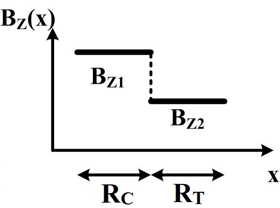
In order to implement a double qubit system, we need two adjacent quantum dots, as has been demonstrated recently in [11] (Fig. 1). It makes use of a magnetic field gradient and exchange interaction between electrons to implement CNOT/controlled-NOT operation. The Hamiltonian for two qubits CNOT operation is given by Eq. 8:
| (8) |
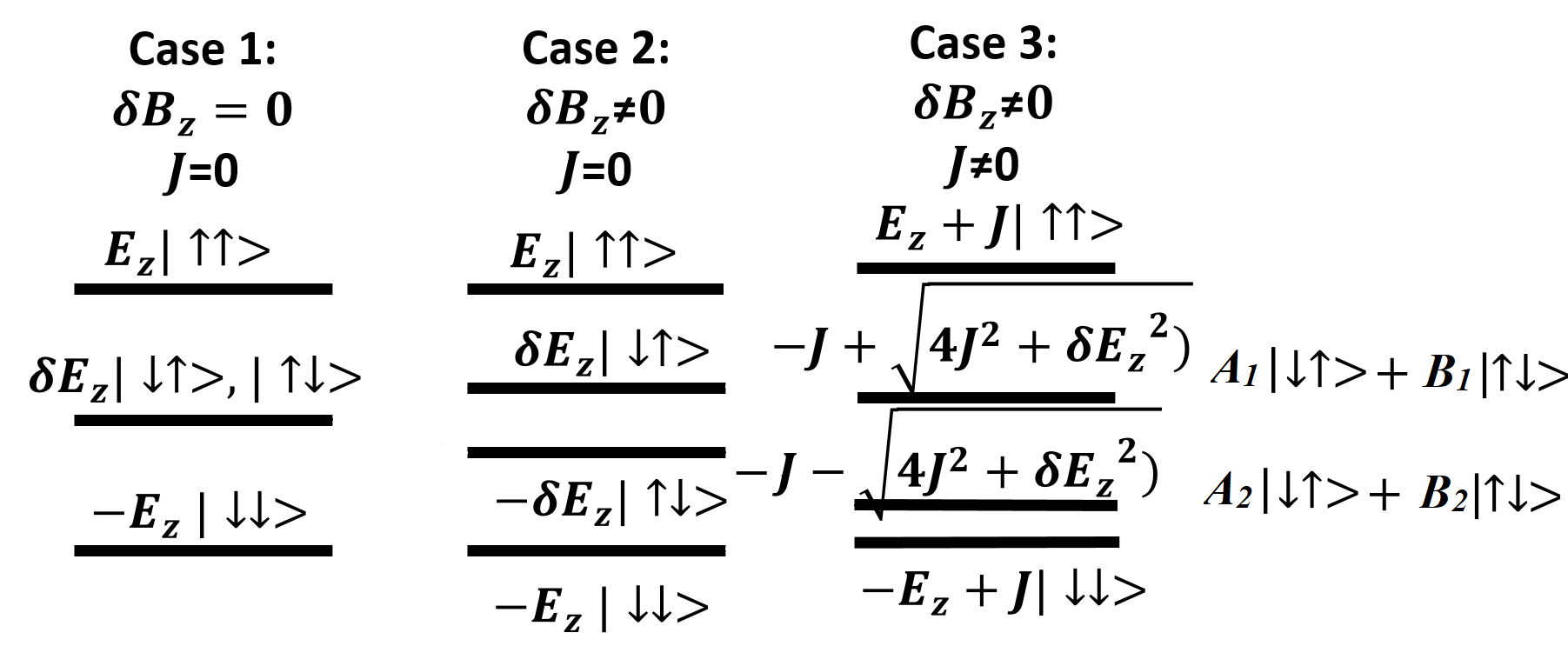
Eq. 8 has been solved using rotating wave approximation (RWA). The results are illustrated in Fig. 2 showing eigenvalue/eigenstates for both zero and non-zero exchange interaction and magnetic field gradient . We assume that the magnetic field is constant along the length of the individual electron wave function. In Eq. 8, is the exchange interaction, , are static magnetic field, is the ac magnetic field, g is electron gyro-magnetic ratio, is Bohr magneton constant, and all the are spin operator for electron and . In CNOT operation, when the control qubit is in state , the state of target qubit is flipped other wise it remains unchanged. This happens because the frequency of corresponds to energygap . When the spin states and occur in superposition owing to high exchange interaction energy value. When is too low, the energy gap between states and is same. In that case, cause transition between both pairs of mentioned energy state, resulting in an erroneous CNOT operation. This restrict value of J to a small range (compared to ) for which we can observe a successful gate operation. Hence, we analyze the effect of externally applied static magnetic fields and not exchange interaction in our study.
There are four energy levels for the two spin system resulting in six positive () and six negative () relaxation operators due to hyperfine noise (Eq. 4, Eq. 5). Similarly, six positive and six negative relaxation operator due to interaction with phonon (Eq. 6, Eq. 7). (Eq. 9) correspond to dephasing operators for two qubit system where we assume = [22]. It is assumed that dephasing time for two qubit system is same as one qubit system.
| (9) |
This methodology was followed, and results for high (Fig. 3) and low values (Fig. 4) of the static magnetic field are plotted. The key results are discussed in SectionV.

IV Three Spin system
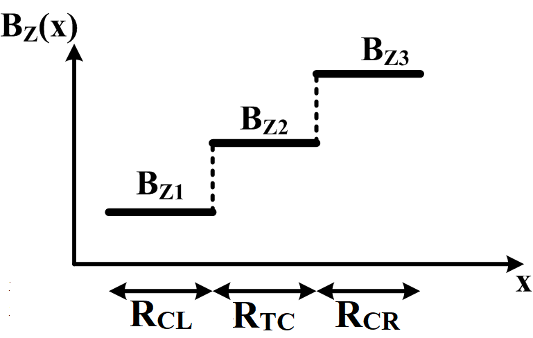
On the similar lines as two qubits system, a system of three spin qubits was used to implement controlled-controlled NOT gate (CCNOT) or Toffoli gate, as illustrated in [23] (Fig. 5). The Toffoli gate uses two control qubits, and based on their states, the target qubit is either flipped or left unchanged. The complete Hamiltonian for three qubits Toffoli system is given by Eq.10, where gives exchange interaction between electron existing between region - and the gives exchange interaction for region - (Fig. 5).
| (10) |
The static magnetic fields , , are used to create a magnetic field gradient where we assume that the magnetic field is constant along the length of the individual electron wave function. is the ac magnetic field that is used to cause state transitions at a particular frequency. When both control qubits are in the state , the state of the target qubit is flipped; otherwise, it remains unchanged. This happens because the frequency of correspond to energy gap .
There are eight energy levels for the three spin system , and resulting in twenty-eight positive () and twenty-eight negative () relaxation operators due to hyperfine noise (Eq. 4,Eq. 5).Similarly, twenty-eight positive and twenty-eight negative relaxation operators due to interaction with phonon (Eq. 6, Eq. 7). (Eq. 11) correspond to dephasing operator for three qubit system where we assume = [22]. It is assumed that dephasing time for three qubit system is same as one qubit system.
| (11) |
This methodology was followed, and results for high (Fig. 6) and low values (Fig. 7) of the static magnetic field are plotted. The key results are discussed in SectionV.
V Results and Analysis
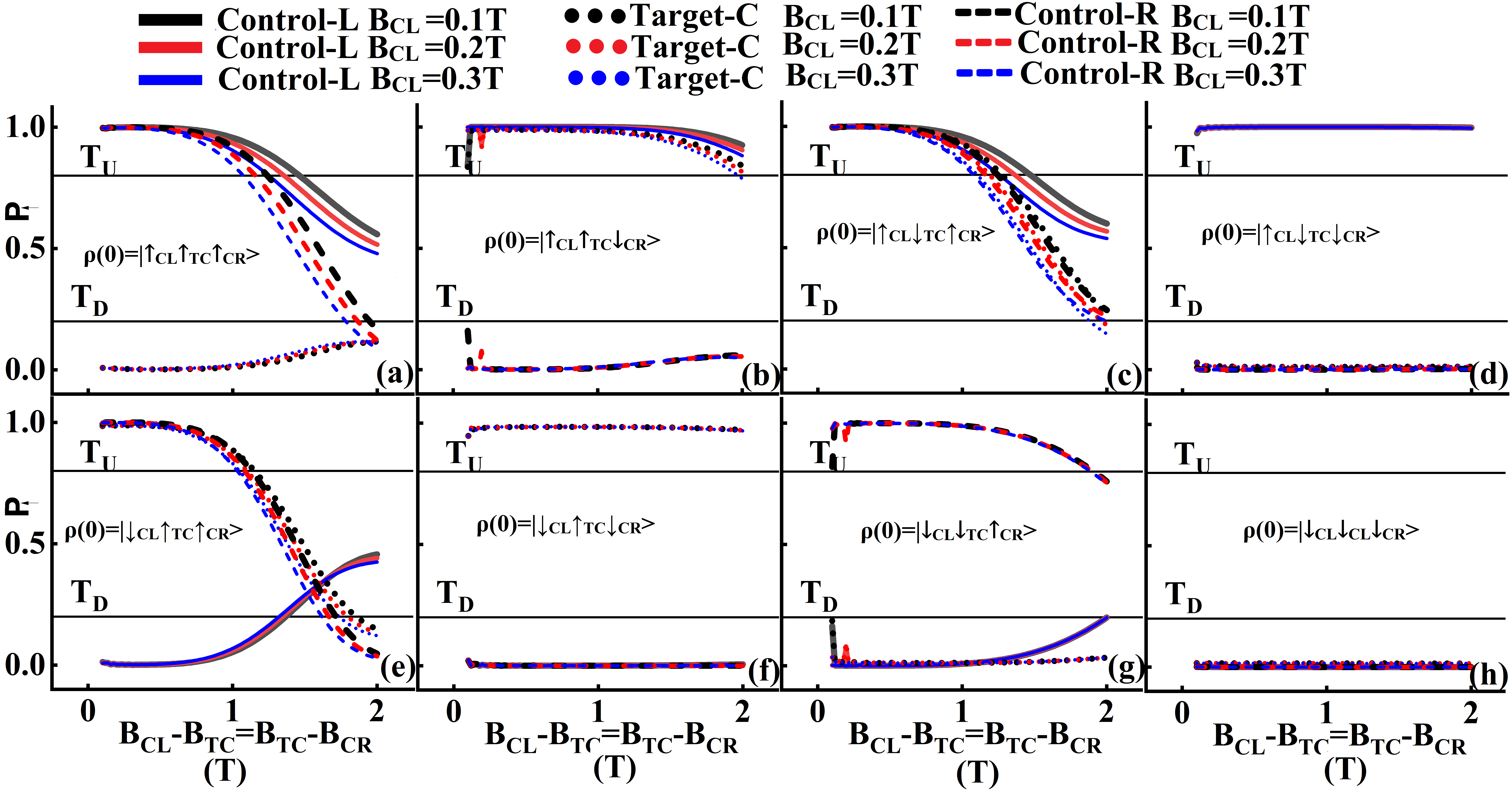
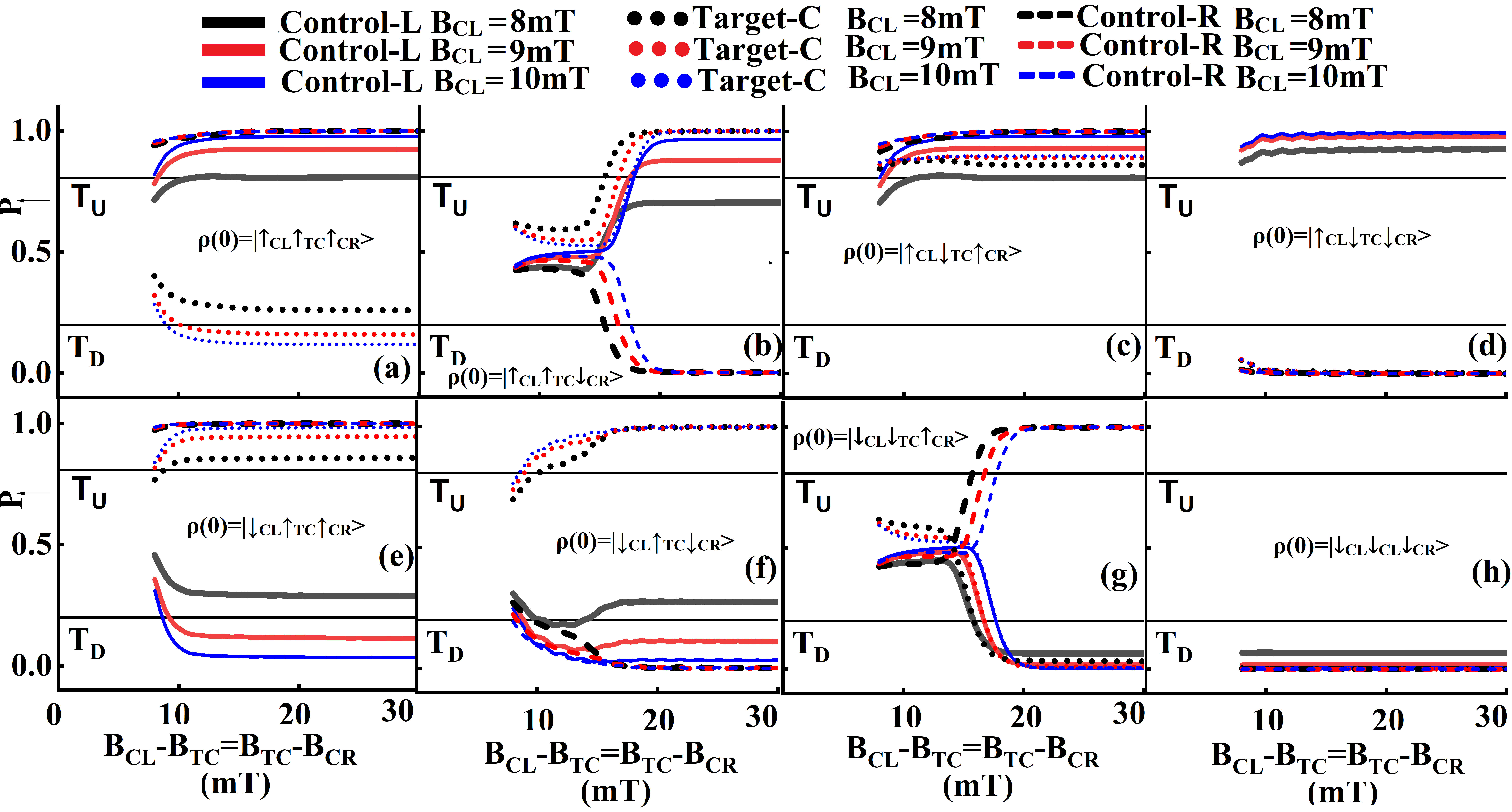
In this section, we discuss the results for a two-qubit CNOT gate at a high magnetic field (Fig. 3) and low magnetic field (Fig.4) at a fixed ac magnetic field. Then a similar analysis is done for a three-qubit Toffoli gate at high (Fig.6) and low magnetic field (Fig.7).
V-A Two spin Analysis
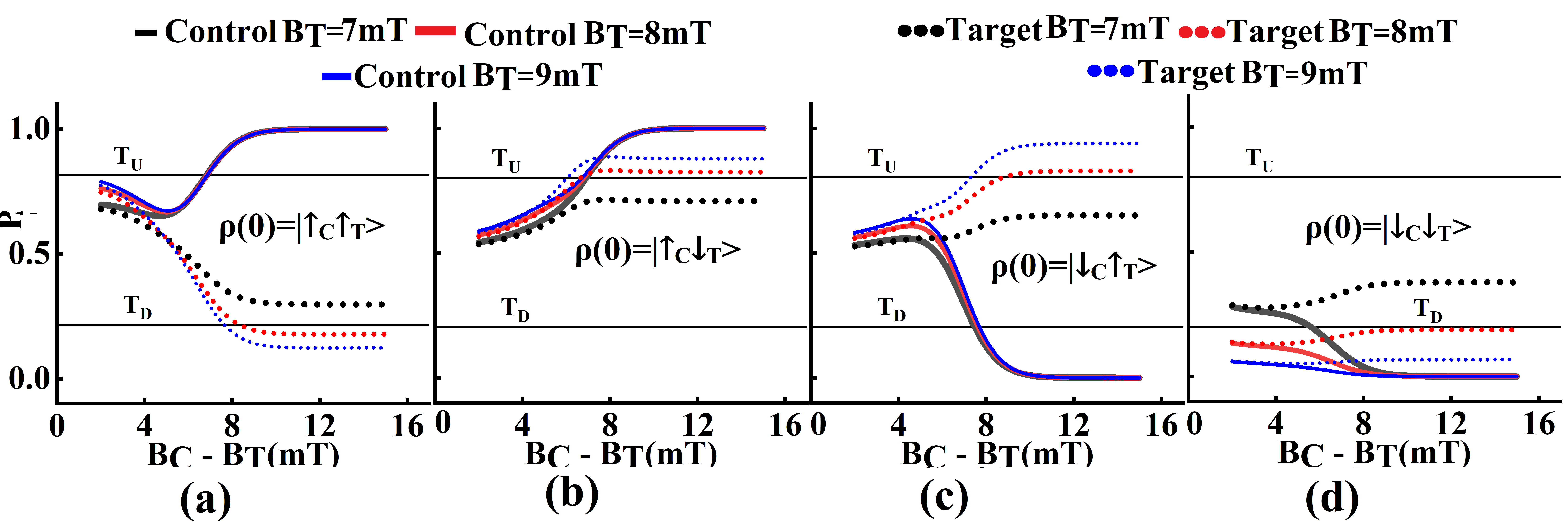
Fig. 3 and Fig. 4 shows a two qubit CNOT response at high and low external magnetic field undergoing decohrence. Each column in both figure correspond to a possible initial state of the system which are , , , . For a single initial state, the solid curve correspond to the value of control qubit whereas dotted curve correspond to of target qubit. value correspond to the probability that electron is in state , taken at time when the target bit gets flipped for CNOT operation () and plotted for various value of gradient (). The different colors depict the magnetic field at target qubit . We also define two threshold levels that can help define gate operations, and . If , we assume our logical state of the system be in . When logical state of the system will be .
At a high magnetic field regime (Fig. 3), the operating range of CNOT will be determined by the minimum value of (among all possible initial states) where the curve of control or target qubit crosses the threshold level ( and ). We observe that the system’s response depends on the initial state. When it is in (Fig 3.a) and (Fig 3.b) the system behaves as CNOT across the parameter range. However, when the system is initially in (Fig 3.c) and (Fig 3.d), the system should remain unchanged but it changes when the curves for control and target qubit crosses the threshold. For e.g. when at , we cannot consider the logical response of system be in when initially the state of qubit was . This behavior is attributed to the spin interaction of confined electrons with phonons. The system shows significant positive relaxation but little negative relaxation.In other words, in Eq.6 and in Eq.7 which will result in . This will result in the highest relaxation rate (among all possible initial states) when the system is initially in . In this regime, relaxation due to hyperfine interaction is negligible (). We conclude that the state with lowest energy put a constraint in CNOT two qubit operation. The magnetic gradient limit for this system is being decided by the control qubit when initially the state is . It happens because of the gradient shape where the control qubit is placed at a higher static magnetic field. For some parameter regimes at a high magnetic field, proper CNOT operation is observed, and this is summarized in Table I.
At low magnetic field (Fig. 4), all possible initial state show relaxation for low value of . In these regimes, the system cannot give a correct CNOT response. E.g. when , for , we do not observe correct CNOT response for initial state (Fig 4.c). The operating range of CNOT is determined by maximum value of (among all possible state) where target/control crosses the threshold. This behavior is attributed to the spin interaction of confined electrons with an ensemble of nuclear spin. The relaxation rate due to hyperfine noise is approximately identical for positive relaxation () Eq. 5 and negative relaxation Eq. 6 (). In this regime, relaxtion due to phononic interaction is negligble (. We observe the decoherence is more dominant for the target qubit since gradient shape is such that . At low magnetic field values, the state showing maximum relaxation () determines the threshold for CNOT. In the low magnetic field, it is the state which has the lowest energy gap with respect to all other states. Table I is a summary of the parameter for which the CNOT operation works properly at a low magnetic field. This methodology can be used to decide the static magnetic field profile and max/min gradient beyond which the system would not behave as a CNOT gate.
| 4mT,0.42eV | 1T | 1.1T-3.01T |
| 0.75T | 0.85T-3.19T | |
| 0.5T | 0.6T-3.35T | |
| 0.04mT,4.2neV | 8mT | 16.60mT |
The lower bound of the static magnetic field gradient for a high magnetic field (few T) is determined by the value of exchange interaction (). In contrast, the upper bound is governed by decoherence due to spin-orbit interaction (SOI)-assisted phonon interaction. The lower bound of the static magnetic field in a low magnetic field regime (few mT) is limited by decoherence due to hyperfine noise. At a high value of magnetic gradient such that energy gap between state , the system show transition for both energy gap, thereby failing CNOT gate operation. This limits the upper bound for CNOT operation at a high static magnetic field.
V-B Three spin Analysis
Just like the two-qubit gate, the results for a three-qubit Toffoli gate are presented in Fig. 6 for a high static magnetic field. We assume the static magnetic field gradient between left control () and center target () qubit to be equal to gradient between center target and right control qubit (). The operating range of Toffoli will be determined by the minimum value of magnetic field gradient (among all possible initial states) for which the curve of either control/target qubit, crosses the threshold level ( and ). When the initial state of system is (Fig.6.h) which has highest energy, it shows negligible decay in given parameter range whereas the lowest energy initial state (Fig.6.a) show maximum decay. The right control qubit of the state decide the maximum range for successful Toffoli operation (since ). E.g. when , at , we cannot consider the logical response of system be in state when initially the state of qubit was . This is due to phononic interaction of three spin confined in quantum dots at high magnetic field values. As mentioned for two qubit case, this happens due to a higher positive relaxation rate (Eq. 5) and lower negative relaxation rate (Eq. 6) i.e. . In this regime, relaxtion due to hyperifne interaction is negligible (). For a certain parameter regime at a high magnetic field, we observe a proper Toffoli operation which is summarized in Table II.
| 4mT,0.42eV,0.42eV | 0.1T | 0.2T-1.17T | 0.3T-2.24T |
| 0.2T | 0.3T-1.35T | 0.4T-2.50T | |
| 0.3T | 0.4T-1.63T | 0.5T-2.96T | |
| 4mT,4.2neV,4.2neV | 9mT | 26.86mT | 44.72mT |
At a low magnetic field (Fig. 7), some states in this regime show less performance degradation compared to others. For example, state (Fig. 7.h) shows negligible decay of response compared to other states even at high gradient. It happens because the state has large energygap with respect to other states. State (Fig. 7.b) is relatively closer to all other states thereby showing maximum relaxation decay. As mentioned for two qubit case, this happens due to similar relaxation rates for positive (Eq. 3) and negative relaxation (Eq. 4) i.e. . In this regime, relaxtion due to hyperifne interaction is negligible (). Table II contains the parameter range for which the Toffoli gate works properly at a low magnetic field.
In summary, the lower bound of the static magnetic field gradient for a high magnetic field (few T) is determined by the value of exchange interaction (, ), while the upper bound is governed by decoherence due to SOI-assisted phonon interaction. The lower bound of the static magnetic field in a low magnetic field regime (few mT) is limited by decohrence due to hyperfine noise. At a high value of magnetic gradient (), when energy gap , the system shows transition for both state-pairs thereby failing Toffoli operation. This limits the upper bound for Toffoli gate operation at high magnetic field.
For the same set of constant values (ac magnetic field and exchange interaction), we observe that a two-qubit CNOT operation has a much wider static magnetic field range than a three-qubit Toffoli gate. This should be the case since more is the number of confined electrons in the system, more will be the decoherence (noise due to hyperfine interaction and SOI assisted phonon interaction). At a higher ac field, these parameters’ magnetic field will improve significantly. This was done for a single-qubit system recently, and we expect it to be valid for a two and three-qubit system as well [24].
VI Conclusion
In this work, we present a scheme for examining a two-qubit CNOT gate and a three-qubit Toffoli gate operation in the presence of noise. We estimate the parameter range of the static magnetic field for which we can have a proper gate operation with nuclear hyperfine noise and phononic noise. In the future, we plan to devise noise cancellation techniques that can improve the gate response and increase the operating range of these parameters. We hope this study can be extended to a larger qubit system to understand various gate operations and would be helpful in understanding the execution of quantum algorithms on quantum dot qubits.
Acknowledgments
This work is supported by the Department of Science and Technology (DST), India with grant no. DST/INSPIRE/04/2018/000023.
References
- [1] P. Benioff, “The computer as a physical system: A microscopic quantum mechanical hamiltonian model of computers as represented by turing machines,” Journal of statistical physics, vol. 22, no. 5, pp. 563–591, 1980.
- [2] R. P. Feynman, “Simulating physics with computers,” in Feynman and computation. CRC Press, 2018, pp. 133–153.
- [3] D. P. DiVincenzo, “The physical implementation of quantum computation,” Fortschritte der Physik: Progress of Physics, vol. 48, no. 9-11, pp. 771–783, 2000.
- [4] C. Kloeffel and D. Loss, “Prospects for spin-based quantum computing in quantum dots,” Annu. Rev. Condens. Matter Phys., vol. 4, no. 1, pp. 51–81, 2013.
- [5] M. A. Eriksson, M. Friesen, S. N. Coppersmith, R. Joynt, L. J. Klein, K. Slinker, C. Tahan, P. Mooney, J. Chu, and S. Koester, “Spin-based quantum dot quantum computing in silicon,” Quantum Information Processing, vol. 3, no. 1, pp. 133–146, 2004.
- [6] D. Loss and D. P. DiVincenzo, “Quantum computation with quantum dots,” Physical Review A, vol. 57, no. 1, p. 120, 1998.
- [7] F. H. Koppens, C. Buizert, K.-J. Tielrooij, I. T. Vink, K. C. Nowack, T. Meunier, L. Kouwenhoven, and L. Vandersypen, “Driven coherent oscillations of a single electron spin in a quantum dot,” Nature, vol. 442, no. 7104, pp. 766–771, 2006.
- [8] B. M. Maune, M. G. Borselli, B. Huang, T. D. Ladd, P. W. Deelman, K. S. Holabird, A. A. Kiselev, I. Alvarado-Rodriguez, R. S. Ross, A. E. Schmitz et al., “Coherent singlet-triplet oscillations in a silicon-based double quantum dot,” Nature, vol. 481, no. 7381, pp. 344–347, 2012.
- [9] M. Veldhorst, J. Hwang, C. Yang, A. Leenstra, B. de Ronde, J. Dehollain, J. Muhonen, F. Hudson, K. M. Itoh, A. Morello et al., “An addressable quantum dot qubit with fault-tolerant control-fidelity,” Nature nanotechnology, vol. 9, no. 12, pp. 981–985, 2014.
- [10] M. Veldhorst, C. Yang, J. Hwang, W. Huang, J. Dehollain, J. Muhonen, S. Simmons, A. Laucht, F. Hudson, K. M. Itoh et al., “A two-qubit logic gate in silicon,” Nature, vol. 526, no. 7573, pp. 410–414, 2015.
- [11] D. M. Zajac, A. J. Sigillito, M. Russ, F. Borjans, J. M. Taylor, G. Burkard, and J. R. Petta, “Resonantly driven cnot gate for electron spins,” Science, vol. 359, no. 6374, pp. 439–442, 2018.
- [12] M. A. Nielsen and I. L. Chuang, “Quantum computation and quantum information,” Phys. Today, vol. 54, no. 2, p. 60, 2001.
- [13] A. W. Harrow, B. Recht, and I. L. Chuang, “Efficient discrete approximations of quantum gates,” Journal of Mathematical Physics, vol. 43, no. 9, pp. 4445–4451, 2002.
- [14] J. M. Taylor, Hyperfine interactions and quantum information processing in quantum dots, 2006, vol. 67, no. 12.
- [15] S. Amasha, K. MacLean, I. P. Radu, D. Zumbühl, M. Kastner, M. Hanson, and A. Gossard, “Electrical control of spin relaxation in a quantum dot,” Physical review letters, vol. 100, no. 4, p. 046803, 2008.
- [16] A. V. Khaetskii and Y. V. Nazarov, “Spin-flip transitions between zeeman sublevels in semiconductor quantum dots,” Physical Review B, vol. 64, no. 12, p. 125316, 2001.
- [17] P. San-Jose, G. Zarand, A. Shnirman, and G. Schön, “Geometrical spin dephasing in quantum dots,” Physical review letters, vol. 97, no. 7, p. 076803, 2006.
- [18] F. Marquardt and V. A. Abalmassov, “Spin relaxation in a quantum dot due to nyquist noise,” Physical Review B, vol. 71, no. 16, p. 165325, 2005.
- [19] M. Borhani, V. N. Golovach, and D. Loss, “Spin decay in a quantum dot coupled to a quantum point contact,” Physical Review B, vol. 73, no. 15, p. 155311, 2006.
- [20] S. Mehl and D. P. DiVincenzo, “Noise analysis of qubits implemented in triple quantum dot systems in a davies master equation approach,” Physical Review B, vol. 87, no. 19, p. 195309, 2013.
- [21] D. Paget, G. Lampel, B. Sapoval, and V. Safarov, “Low field electron-nuclear spin coupling in gallium arsenide under optical pumping conditions,” Physical review B, vol. 15, no. 12, p. 5780, 1977.
- [22] F. Koppens, K. Nowack, and L. Vandersypen, “Spin echo of a single electron spin in a quantum dot,” Physical Review Letters, vol. 100, no. 23, p. 236802, 2008.
- [23] M. Gullans and J. Petta, “Protocol for a resonantly driven three-qubit toffoli gate with silicon spin qubits,” Physical Review B, vol. 100, no. 8, p. 085419, 2019.
- [24] T. Sarkar, Y. Tiwari, and V. S. Poonia, “Impact of ac magnetic field on decoherence of quantum dot based single spin qubit system,” arXiv preprint arXiv:2201.06121, 2022.