High-level Intellectual Property Obfuscation via Decoy Constants
Abstract
This paper presents a high-level circuit obfuscation technique to prevent the theft of intellectual property (IP) of integrated circuits. In particular, our technique protects a class of circuits that relies on constant multiplications, such as filters and neural networks, where the constants themselves are the IP to be protected. By making use of decoy constants and a key-based scheme, a reverse engineer adversary at an untrusted foundry is rendered incapable of discerning true constants from decoy constants. The time-multiplexed constant multiplication (TMCM) block of such circuits, which realizes the multiplication of an input variable by a constant at a time, is considered as our case study for obfuscation. Furthermore, two TMCM design architectures are taken into account; an implementation using a multiplier and a multiplierless shift-adds implementation. Optimization methods are also applied to reduce the hardware complexity of these architectures. The well-known satisfiability (SAT) and automatic test pattern generation (ATPG) attacks are used to determine the vulnerability of the obfuscated designs. It is observed that the proposed technique incurs small overheads in area, power, and delay that are comparable to the hardware complexity of prominent logic locking methods. Yet, the advantage of our approach is in the insight that constants – instead of arbitrary circuit nodes – become key-protected.
Index Terms:
hardware obfuscation, reverse engineering, IP obfuscation, SAT attack, digital FIR filter design.I Introduction
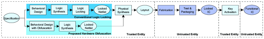
The involvement of multiple entities in the design and fabrication process of integrated circuits (ICs) potentially leads to security threats, such as reverse engineering, overbuilding, and insertion of malicious hardware Trojans [1, 2, 3]. Many efficient techniques, such as watermarking [4], IC metering [5], IC camouflaging [6], and logic locking [7], have been proposed to address these issues. Among these techniques, logic locking stands out, offering a protection against a diverse array of adversaries [8]. Logic locking inserts additional logic into a circuit, such as XOR/XNOR gates [9], AND/OR gates [10], or look-up tables [11], driven by a secret key, so that the circuit behaves as specified only when the correct key inputs are applied. The logic locking and activation of a locked circuit in the IC design flow are shown in Fig. 1.
Many widely employed circuits, such as artificial neural networks (ANNs) and finite impulse response (FIR) filters, require the multiplication of constant(s) by input variable(s). In these applications, ANN weights and filter coefficients are constants determined beforehand using sophisticated algorithms [12, 13]. These constants are, therefore, an intellectual property (IP). Hence, there is a clear interest in protecting the constants since they are valuable, perhaps even more so than the circuit architecture, e.g., the number of layers in an ANN or the multiplier and accumulate block in a filter.
The hardware complexity of ANNs and filters increases as the number of neurons and filter coefficients increases, respectively, restricting their applications on design platforms with a limited number of computing resources, such as FPGAs, and on designs having a strict area requirement [14, 15]. To reduce the design area, taking into account an increase in latency, such IPs are generally implemented under a folded architecture re-using the computing resources [16]. In a folded design, the time-multiplexed constant multiplication (TMCM) operation is a fundamental block that realizes the multiplication of an input variable by a single constant selected from a set of multiple constants at a time [17, 18]. Since a design’s layout is inevitably available to an adversary at an untrusted foundry, constants of the TMCM block are vulnerable to reverse engineering even if a logic locking method is employed. Logic locking, despite its popularity, is not particularly well suited for hiding constants or similar design features.
Given the limitations discussed above, the main contribution of this paper is an obfuscation technique that protects the sensitive constants from an adversary at an untrusted foundry by hiding them among decoy constants using additional logic with keyed inputs. The proposed technique implements the obfuscation of the TMCM operation at the register-transfer level (RTL) as shown in Fig. 1. This enables a synthesis tool to optimize the design complexity and also promotes resource sharing, as opposed to traditional logic locking methods which are applied post synthesis at gate level. This paper considers two TMCM design architectures referred to as tmcm-mul and tmcm-sa. While the former utilizes multiplexors and a multiplier, the latter utilizes shifts, adders, subtractors, adders/subtractors (determined by a select input), and multiplexors under a shift-adds architecture, but no multiplier.
The rest of this paper is organized as follows. Section II gives the background concepts on the TMCM block and folded FIR filter design and presents the related work. The proposed TMCM obfuscation technique is described in Section III. Experimental results are presented in Section IV and finally, Section V concludes the paper.
II Background
II-A Time-Multiplexed Constant Multiplication
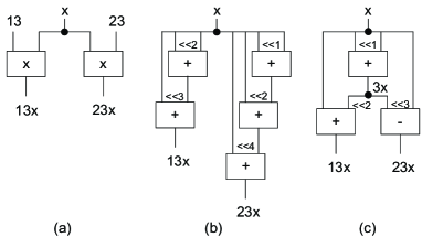
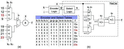
Multiplication of constant(s) by input variable(s) is generally realized under a shift-adds architecture using only shifts, adders, and subtractors [19]. Shifts by a constant value can be realized using only wires which represent no hardware cost. A straightforward way of realizing constant multiplications under a shift-adds architecture is the digit-based recoding (DBR) technique [20], which has two main steps: (i) define the constants under a particular number representation, e.g., binary; (ii) for the nonzero digits in the representation of constants, shift the input variables according to digit positions and add/subtract the shifted variables with respect to digit values. As a simple example, consider the multiplication of constants and by the input variable in the multiple constant multiplication (MCM) block shown in Fig. 2(a). The decompositions of constants under binary are given as follows:
which lead to a multiplierless design with 5 operations as shown in Fig. 2(b). Over the years, algorithms have been proposed for minimizing the number of adders and subtractors by maximizing the sharing of partial products [21]. For our example, the exact algorithm of [22] finds a solution with 3 operations, sharing the subexpression as shown in Fig. 2(c).
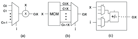
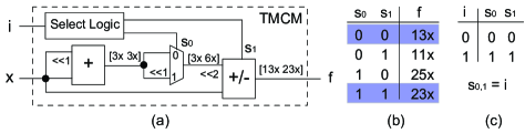
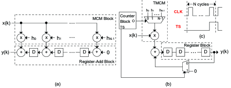
On the other hand, the combinational TMCM operation can be implemented under different architectures as shown in Fig. 3 [18]. Given constants, the TMCM operation can be implemented using an -to-1 multiplexor and a generic multiplier, where the primary select input with determines which constant is multiplied by the input variable (cf. mux-mul architecture in Fig. 3(a)). It can also be realized using an MCM block, which implements the multiplications of constants by the input variable, and an -to-1 multiplexor (cf. mcm-mux architecture in Fig. 3(b)). Furthermore, it can be implemented using adders, subtractors, adders/subtractors, and multiplexors (cf. mux-add architecture in Fig. 3(c)). Novel methods have been introduced to reduce the hardware complexity of the TMCM operation under the mux-add architecture [17, 18]. As a simple example, consider the TMCM operation realizing the constant multiplications of and at a time under the mux-add architecture. Fig. 4(a) presents the solution of the algorithm of [18], where the constant multiplications to be computed in time are given between square brackets in order. Note that the adder/subtractor behaves as an adder and a subtractor when its select input is 0 and 1, respectively. All possible values at the output of the TMCM operation under the select inputs of the multiplexor and adder/subtractor are given in Fig. 4(b). The TMCM operation can also generate and . To obtain the desired outputs under the primary select input , the select logic is required to map to the select inputs of the multiplexor and the adder/subtractor, i.e., , as shown in Fig. 4(c).
II-B Folded Implementation of Digital FIR Filters
Digital filtering is frequently used in digital signal processing (DSP) applications and FIR filters are generally preferred due to their stability and linear phase property [23]. The output of an -tap FIR filter is computed as , where is the filter length, is the filter coefficient, and is the previous filter input with . Fig. 5(a) presents the parallel design of the transposed form FIR filter. On the other hand, Fig. 5(b) shows its folded design. The -bit counter counts from 0 to , generating the timing signal shown in Fig. 5(c). In this figure, denotes the clock signal fed to all registers which was not shown in Figs. 5(a)-(b) for the sake of clarity. The register block includes cascaded registers whose counterparts in the parallel design are the ones in the register-add block. Although the complexity of the filter design is reduced under the folded architecture by reusing the common operations, the filter output is obtained in clock cycles.
II-C Related Work
Over the years, many defense and attack techniques have been introduced to lock logic circuits and determine the key values of the locked circuits, respectively [24]. Among the attacks against logic locking, the satisfiability (SAT) based attack [25] is a powerful one, which was able to overcome the defenses existing at the time of its publication, such as the logic locking techniques of [9, 10]. In recent years, a large number of SAT attack resilient logic locking methods have been introduced [26, 8].
Efficient hardware obfuscation techniques proposed to protect IPs have been presented in [27, 28, 29]. For the obfuscation of DSP circuits, a novel approach that uses high-level transformations, a key-based finite-state machine and a reconfigurator was introduced in [30]. The use of decoys in obfuscation has been utilized in [31], but in a manner that is not related to the IP itself, as the decoys are keyed gates. To make the reverse engineering of coefficients of an FIR filter harder for an end-user, adding input and output noises was proposed in [32]. To the best of our knowledge, the use of decoys to hide the target constants of an IP at RTL has not been explored before.
III The Proposed Obfuscation Method
Although target constants can be stored in a tamper-proof memory as the keys in conventional logic locking, this would prevent both sharing of hardware resources and use of a multiplierless design which can lead to a significant reduction in hardware complexity when utilized as shown in Section II-A. Thus, given a set of target constants , primary select inputs , where , and key inputs , the proposed obfuscation technique initially assigns decoy constants to each target constant in an iterative manner as shown in Algorithm 1. In the AssignDecoy function of Algorithm 1, the decoy constants are preferred to have a small Hamming distance with respect to the target constant under the binary representation. This is simply because synthesis tools can also implement constant multiplications under a shift-adds architecture similar to the DBR technique [20] and maximize the sharing of partial products among constant multiplications as shown in Fig. 2. The decoys are selected in between , where , , denotes the maximum bit-width of target constants. The difference on bits between the target and decoy constants starts from the least significant bit. Also, the decoys are decided to be unique to increase the obfuscation. For our example in Fig. 4 with is 2, given the number of key inputs is 4, for the target constant 13 , the decoys 9 , 12 , and 15 are selected and for the target constant 23 , the decoys 19 , 21 , and 22 are chosen, using a total of 6 decoys.
Then, the obfuscated TMCM operation is implemented based on the given design architecture, i.e., tmcm-mul or tmcm-sa. The tmcm-mul architecture is based on the mux-mul architecture shown in Fig. 3(a). Initially, for each target constant, a multiplexor is used to select the target and its decoy constant(s) using key input(s). The locations of the target and decoy constants at the multiplexor inputs are determined randomly. The number of inputs of these multiplexors is equal to the number of decoy constants assigned to the target constant plus 1 (denoting the target constant). Then, another multiplexor is used to realize the constant multiplication in the TMCM block in the given order using the primary select input . The number of inputs of this multiplexor is equal to . Finally, a multiplier is used to realize the constant multiplication. Its size is equal to , where denotes the bit-width of the input variable . For our example in Fig. 4, the realization of the obfuscated TMCM block is illustrated in Fig. 6(a). The constant multiplications and are computed when and , respectively, where is the don’t care. Note that a wrong key leads to at least one decoy multiplication at a time, e.g., if , the TMCM block generates and when is 0 and 1, respectively. Hence, in a folded design such as FIR filter in Fig. 5(b), whose TMCM block is obfuscated using the proposed method, a wrong key always generates a wrong output.
The tmcm-sa architecture is based on the mux-add architecture shown in Fig. 3(c). Initially, given the order of target and decoy constant multiplications, an encoder logic, which maps the key inputs and primary select to the select inputs of the TMCM operation, i.e., , is generated. Note that the encoder logic has inputs and outputs, where denotes the total number of decoy constants. Then, the constant multiplications in the same order are given to the algorithm of [18] and an optimized implementation is found under the shift-adds architecture. For our simple example, given the order of target and decoy constant multiplications as in Fig. 6(a), i.e., , the realization of the obfuscated TMCM operation is shown in Fig. 6(b) including the encoder and select tables. Note that the select logic, which is implemented by the algorithm of [18] to realize the constant multiplications in a given order, maps the select inputs of the TMCM operation, i.e., , to the select inputs of adders/subtractors and multiplexors in the TMCM design, i.e., .
The TMCM operation can also be obfuscated based on the mcm-mux architecture shown in Fig. 3(b). In our obfuscated implementation, the MCM block realizes the target and decoy constant multiplications. For each target constant with decoys, a multiplexor is used to select the constant multiplication using the key inputs. Finally, the multiplexor with the primary select input , which generates the output, is used. However, in this case, it was observed that the key inputs are so vulnerable to the logic locking attacks since they can be observed easily at the output. The key inputs in the tmcm-mul and tmcm-sa architectures are behind many logic operators, which is preferred from an obfuscation point of view.
To automate the design and verification process, a computer-aided design (CAD) tool was developed for the obfuscation of the TMCM operation. The CAD tool takes the target constants, the number of key inputs, and the design architecture as inputs, and generates the description of the obfuscated TMCM design in Verilog, the testbench for verification, and synthesis and simulation scripts. Note that the designs under both architectures are described in a behavioral fashion. While targets and decoys are expressed as constants in the RTL code under the tmcm-mul architecture, the TMCM block, which realizes the multiplication of the input variable by a target or decoy constant at a time, is generated by the method of [18] under the tmcm-sa architecture.
IV Experimental Results
As an experiment set, three FIR filters, selected from the FIR filter benchmark suite [33], were used. Their specifications are given in Table I, where and are the number of filter coefficients and primary select inputs, repectively, and is the maximum bit-width of filter coefficients. Note that #in and #out stand respectively for the number of inputs and outputs of the TMCM design computed when the bit-width of the filter input is 32.
| Filter | Coefficient Details | TMCM Details | ||||
|---|---|---|---|---|---|---|
| Index | Name | n | m | mbw | #in | #out |
| 1 | Johansson08_30 | 30 | 5 | 10 | 37 | 42 |
| 2 | Shi11_S2 | 60 | 6 | 10 | 38 | 42 |
| 3 | Maskell07_A108 | 108 | 7 | 9 | 39 | 41 |
Conventional logic locking was applied to the combinational TMCM blocks of FIR filters under the mux-mul and mux-add architectures, while the proposed technique was used to obfuscate these combinational TMCM blocks under the tmcm-mul and tmcm-sa architectures. Logic synthesis was performed by Cadence Genus using a commercial 65nm cell library. The functionality of designs was verified on 10,000 randomly generated input signals in simulation, from which the switching activity information is collected and utilized by the synthesis tool to compute power dissipation. The SAT and automatic test pattern generation (ATPG) based attacks developed in [25] were used to check the resiliency of locked and obfuscated TMCM designs after they were synthesized into a gate-level netlist. Note that the ATPG based attack of [25] initially uses ATPG methods to determine key inputs and then, the SAT based attack to find the rest of key inputs undetermined by ATPG methods. As a common practice, a time limit of 1 day was given to the attacks which were run on a computing cluster including Intel Xeon processing units at 2.4GHz with 40 cores and 96GB memory.
Tables II and III present the gate-level design results of locked and obfuscated combinational TMCM blocks, respectively, when is 32. The number of key inputs is 32, 64, and 128 for the FIR filter Johansson08_30, Shi11_S2, and Maskell07_A108, respectively. In these tables, area, delay, and power stand for the total area in , delay in the critical path in , and total power dissipation in , respectively. Also, Asat and Aatpg denote the SAT and ATPG based attacks, respectively, where time is their run-time in seconds. In Table II, LLT denotes a logic locking technique, where rand, iolts, sar, and sfll111The parameter of the SFLL-HD technique, which is used to adjust the tradeoff between SAT attack resiliency and output corruption, was set to in our experiments. are the methods of [9], [10], [26], and [8], respectively.
| Filter | Architecture | LLT | Synthesis Results | Asat | Aatpg | ||
|---|---|---|---|---|---|---|---|
| Index | area | delay | power | time | time | ||
| 1 | mux-mul | rand | 2775 | 5558 | 1147 | 49743 | 22 |
| iolts | 2802 | 4355 | 1229 | >1day | >1day | ||
| sar | 2927 | 4436 | 1225 | >1day | >1day | ||
| sfll | 4020 | 4473 | 2391 | 301 | 100 | ||
| mux-add | rand | 3071 | 6336 | 1393 | 65002 | 1377 | |
| iolts | 2894 | 5234 | 1386 | >1day | >1day | ||
| sar | 2999 | 5122 | 1390 | >1day | >1day | ||
| sfll | 4092 | 5202 | 2696 | 7215 | 367 | ||
| 2 | mux-mul | rand | 3104 | 5588 | 1334 | >1day | 18 |
| iolts | 3035 | 4558 | 1279 | >1day | >1day | ||
| sar | 3168 | 4603 | 1236 | >1day | >1day | ||
| sfll | 5648 | 6290 | 4998 | >1day | >1day | ||
| mux-add | rand | 3570 | 6661 | 1536 | >1day | >1day | |
| iolts | 3260 | 5939 | 1400 | >1day | >1day | ||
| sar | 3395 | 5730 | 1397 | >1day | >1day | ||
| sfll | 5913 | 6136 | 5021 | >1day | >1day | ||
| 3 | mux-mul | rand | 3020 | 6268 | 1186 | 50758 | 33327 |
| iolts | 2759 | 4765 | 1112 | 21104 | 23423 | ||
| sar | 3070 | 4945 | 1121 | >1day | >1day | ||
| sfll | 9313 | 11629 | 17585 | >1day | >1day | ||
| mux-add | rand | 3913 | 6705 | 1126 | 10555 | 7254 | |
| iolts | 3462 | 5189 | 1099 | 19235 | 20885 | ||
| sar | 3703 | 5149 | 1070 | >1day | >1day | ||
| sfll | 10000 | 11909 | 17487 | >1day | >1day | ||
| Filter | Architecture | Synthesis Results | Asat | Aatpg | ||
|---|---|---|---|---|---|---|
| Index | area | delay | power | time | time | |
| 1 | tmcm-mul | 2749 | 5341 | 1170 | >1day | >1day |
| tmcm-sa | 3445 | 6651 | 2024 | >1day | >1day | |
| 2 | tmcm-mul | 4362 | 5810 | 3546 | >1day | >1day |
| tmcm-sa | 4318 | 7139 | 2169 | >1day | >1day | |
| 3 | tmcm-mul | 4595 | 5636 | 3522 | >1day | >1day |
| tmcm-sa | 4155 | 6256 | 1895 | >1day | >1day | |
Observe from Table II that while the TMCM designs locked by rand, iolts and sfll techniques are vulnerable to the SAT and ATPG based attacks, the sfll technique leads to locked designs which have larger hardware complexity than those of any other techniques used in this paper. Besides, the sar method generates locked designs comparable to those generated by the iolts and rand methods in terms of hardware complexity, but more resilient to the attacks. On the other hand, observe from Table III that the proposed obfuscation technique generates locked designs that the SAT and ATPG based attacks find hard to decrypt. Moreover, the designs obfuscated by the proposed technique have less hardware complexity than those locked by the sfll technique. When compared to the designs locked by the sar technique222Designs locked by both sar and the proposed obfuscation methods could not be decrypted by the SAT and ATPG based logic locking attacks in a given time-limit. under the mux-mul architecture, the area, delay, and power dissipation can increase up to 49%, 26%, and 214% in the obfuscated TMCM designs under the tmcm-mul architecture. However, the obfuscation technique can find a TMCM design with less area on the filter Johansson08_30. With respect to the synthesis results of designs locked by the sar technique under the mux-add architecture, the area, delay, and power dissipation can increase up to 27%, 29%, and 77% in the obfuscated designs under the tmcm-sa architecture. However, we note that the main advantage of the proposed obfuscation method is to protect the target constants from reverse engineering, which cannot be guaranteed by a traditional logic locking technique. Also, sar has an extremely low impact on circuit functionality, meaning that for each input pattern, there is only one key value that leads to corruption at outputs, whereas, our method has a high impact as shown in Fig. 7. Furthermore, observe from Table III that the tmcm-sa architecture can lead to designs with less area and power consumption when compared to the tmcm-mul architecture, e.g., the FIR filter Shi11_S2 and Maskell07_A108. The delay of obfuscated designs under the tmcm-sa architecture is generally larger than that of designs under the tmcm-mul architecture because of a large number of operations in series in the TMCM blocks obtained by the algorithm of [18].
To explore the impact of the number of key inputs on the hardware complexity and resiliency to the attacks of the obfuscated designs, the TMCM block of the FIR filter Johansson08_30 is implemented with a value in between 16 and 80, increased in a step of 16. Table IV shows the synthesis results of TMCM designs and solutions of the attacks.
| Architecture | Synthesis Results | Asat | Aatpg | |||
|---|---|---|---|---|---|---|
| area | delay | power | time | time | ||
| 16 | tmcm-mul | 2688 | 5390 | 1084 | 773 | 26 |
| tmcm-sa | 3398 | 5442 | 1647 | >1day | 34 | |
| 32 | tmcm-mul | 2749 | 5341 | 1170 | >1day | >1day |
| tmcm-sa | 3445 | 6651 | 2024 | >1day | >1day | |
| 48 | tmcm-mul | 2862 | 5696 | 1282 | >1day | >1day |
| tmcm-sa | 3611 | 6586 | 1720 | >1day | >1day | |
| 64 | tmcm-mul | 4420 | 5762 | 3132 | >1day | >1day |
| tmcm-sa | 3697 | 7224 | 1874 | >1day | >1day | |
| 80 | tmcm-mul | 4631 | 5656 | 3241 | >1day | >1day |
| tmcm-sa | 4515 | 7618 | 2990 | >1day | >1day | |
Observe from Table IV that as increases, the hardware complexity of the obfuscated designs is increased. However, the increase ratio in area and power dissipation of the designs under the tmcm-mul architecture is larger than that of the designs under the tmcm-sa architecture, such that the area and power dissipation of the design under the tmcm-sa architecture become smaller than those of designs under the tmcm-mul architecture as increases. This is because as increases, the size of multiplexors increases under the tmcm-mul architecture and the complexity of the TMCM design under the tmcm-sa architecture increases slightly due to the optimization algorithm of [18]. Also, as decreases, the obfuscated TMCM design becomes less resilient to attacks.
To find the impact of the filter input bit-width on the hardware complexity and resiliency to the attacks of the obfuscated designs, the TMCM block of the FIR filter Shi11_S2 is designed when is 64 and is in between 16 and 32, increased in a step of 4. Table V shows the synthesis results of the obfuscated TMCM designs and solutions of the attacks.
| Architecture | Synthesis Results | Asat | Aatpg | |||
|---|---|---|---|---|---|---|
| area | delay | power | time | time | ||
| 16 | tmcm-mul | 2145 | 3611 | 980 | 177 | 17902 |
| tmcm-sa | 2741 | 5291 | 1269 | 409 | 1181 | |
| 20 | tmcm-mul | 2589 | 4670 | 1466 | 1369 | >1day |
| tmcm-sa | 3127 | 5691 | 1555 | 2682 | 3626 | |
| 24 | tmcm-mul | 3144 | 4603 | 1970 | 28003 | >1day |
| tmcm-sa | 3507 | 6159 | 1802 | 13148 | 7848 | |
| 28 | tmcm-mul | 3836 | 5000 | 2700 | >1day | >1day |
| tmcm-sa | 3855 | 6644 | 2087 | 27221 | 31877 | |
| 32 | tmcm-mul | 4362 | 5810 | 3546 | >1day | >1day |
| tmcm-sa | 4318 | 7139 | 2169 | >1day | >1day | |
Observe from Table V that as increases, the hardware complexity of the TMCM designs increases since the size of operators increases. Note that the size of a multipler under the tmcm-mul architecture has a larger impact on the hardware complexity when compared to the size of adders, subtractors, and adders/subtractors under the tmcm-sa architecture since area and power dissipation of designs under the tmcm-mul architecture become larger than those of designs under the tmcm-sa architecture as increases. Observe that the resiliency of obfuscated designs to the attacks also increases as increases. This is mainly because the search space of the problem of finding key inputs increases as increases.
To explore the impact of the decoy selection method (DSM) on the hardware complexity and resiliency to the attacks of the obfuscated designs, the TMCM blocks of FIR filters are also implemented when decoys are chosen randomly, respecting . In these designs, is 32 and is 32, 64, and 128 for the FIR filter Johansson08_30, Shi11_S2, and Maskell07_A108, respectively. Table VI presents the synthesis results of the obfuscated TMCM designs obtained using different DSMs and the solutions of the attacks.
| Filter | Architecture | DSM | Synthesis Results | Asat | Aatpg | ||
|---|---|---|---|---|---|---|---|
| Index | area | delay | power | time | time | ||
| 1 | tmcm-mul | random | 4382 | 5388 | 3115 | >1day | 3580 |
| proposed | 2749 | 5341 | 1170 | >1day | >1day | ||
| tmcm-sa | random | 3489 | 5360 | 1767 | >1day | >1day | |
| proposed | 3445 | 6651 | 2024 | >1day | >1day | ||
| 2 | tmcm-mul | random | 4740 | 5756 | 3784 | >1day | >1day |
| proposed | 4362 | 5810 | 3546 | >1day | >1day | ||
| tmcm-sa | random | 4475 | 6208 | 1800 | 26299 | 42029 | |
| proposed | 4318 | 7139 | 2169 | >1day | >1day | ||
| 3 | tmcm-mul | random | 4833 | 5756 | 3442 | >1day | >1day |
| proposed | 4595 | 5636 | 3522 | >1day | >1day | ||
| tmcm-sa | random | 4073 | 7529 | 1644 | 42414 | >1day | |
| proposed | 4155 | 6256 | 1895 | >1day | >1day | ||
| Filter | Technique | Architecture | Synthesis Results | ||
|---|---|---|---|---|---|
| Index | area | delay | power | ||
| 1 | Original | mux-mul | 14082 | 6362 | 1386 |
| mux-add | 14396 | 6797 | 1592 | ||
| Obfuscated | tmcm-mul | 14171 | 6101 | 1386 | |
| tmcm-sa | 14973 | 7548 | 1969 | ||
| 2 | Original | mux-mul | 25007 | 6045 | 2011 |
| mux-add | 25485 | 6789 | 2242 | ||
| Obfuscated | tmcm-mul | 26486 | 6298 | 2382 | |
| tmcm-sa | 26813 | 8172 | 2722 | ||
| 3 | Original | mux-mul | 41391 | 6260 | 3200 |
| mux-add | 42238 | 6652 | 3228 | ||
| Obfuscated | tmcm-mul | 43379 | 6568 | 3630 | |
| tmcm-sa | 43738 | 8422 | 4083 | ||
Observe from Table VI that because the proposed DSM favors unique decoy constants with a small Hamming distance value with respect to the associated target constant, it generally leads to obfuscated TMCM designs with a smaller area when compared to the random decoy selection under both design architectures, except the FIR filter Maskell07_A108 under the tmcm-sa architecture. Random decoy selection can also create vulnerabilities on the key inputs which is anticipated due to the use of common decoys for different target constants.
To investigate the impact of obfuscation of the TMCM block in filter design, these FIR filters are implemented as shown in Fig. 5(b) when their TMCM blocks are realized under the mux-mul and mux-add architectures and these designs are compared with filters including the obfuscated TMCM blocks generated under the tmcm-mul and tmcm-sa architectures. Table VII shows the synthesis results obtained when is 32 and is 32, 64, and 128 for the FIR filter Johansson08_30, Shi11_S2, and Maskell07_A108, respectively.
Observe from Table VII that the hardware obfuscation on the TMCM block of an FIR filter under the tmcm-mul (tmcm-sa) architecture can respectively increase the area, delay, and power dissipation up to 5.5% (4.9%), 4.6% (21.0%), and 15.5% (20.9%) when compared to the original FIR filters under the mux-mul (mux-add) architecture. Note that the TMCM block has less impact on the area of a folded FIR filter with respect to the registers. Hence, an FIR filter can be obfuscated with a small increase in area.
As opposed to existing logic locking techniques, measuring bit-level corruption at the outputs is not an appropriate metric for a filter. Instead, to explore the impact of decoys on the filter behavior, its zero-phase frequency response is computed based on the original coefficients and the constants selected randomly from the original coefficients and decoys. Fig. 7 shows the behavior of the filter Maskell07_A108 when is 128 and a correct (blue) and 100 wrong (red) keys are applied.
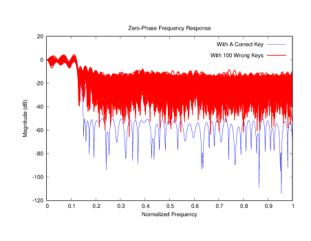
Observe from Fig. 7 that the decoys can alter the filter design characteristics, obfuscating the filter behavior. Note that decoys can be selected to change the filter behavior completely under each possible wrong key, considering also the hardware complexity and resiliency to the logic locking attacks.
V Conclusions
This paper presented a hardware obfuscation technique that prevents an adversary at an untrusted foundry from reverse engineering the constants of a TMCM block, a fundamental operation in the folded design of many IPs, such as ANNs and DSP circuits. The proposed technique obfuscates the target constants of the TMCM block using unique decoy constants and additional logic with keyed inputs. The obfuscation process takes place at RTL before logic synthesis, rather than at gate-level as in traditional logic locking schemes. It is observed that the proposed technique generates obfuscated TMCM designs that are resilient to well-known logic locking attacks. The proposed design architectures introduce alternative realizations of the TMCM block with different hardware complexity and resiliency to the attacks, enabling a designer to choose the one that fits best in an application. In any case, the true IP of these designs, i.e., the constants themselves, can be protected.
As a future work, the impact of synthesis optimizations on the hardware complexity and resiliency of the obfuscated designs is being explored.
Acknowledgment
This work has been partially conducted in the project “ICT programme” which was supported by the European Union through the European Social Fund. It was also partially supported by European Union’s Horizon 2020 research and innovation programme under grant agreement No 952252 (SAFEST) and by the Estonian Research Council grant MOBERC35.
References
- [1] Defence Science Board Task Force. (2015, February) On High Performance Microchip Supply Chain. [Online]. Available: https://dsb.cto.mil/reports/2000s/ADA435563.pdf
- [2] R. Torrance and D. James, “The State-of-the-Art in Semiconductor Reverse Engineering,” in DAC, 2011, p. 333–338.
- [3] R. Karri, J. Rajendran, K. Rosenfeld, and M. Tehranipoor, “Trustworthy Hardware: Identifying and Classifying Hardware Trojans,” Computer, vol. 43, no. 10, p. 39–46, 2010.
- [4] A. B. Kahng, J. Lach, W. H. Mangione-Smith, S. Mantik, I. L. Markov, M. Potkonjak, P. Tucker, H. Wang, and G. Wolfe, “Watermarking Techniques for Intellectual Property Protection,” in DAC, 1998, pp. 776–781.
- [5] F. Koushanfar and G. Qu, “Hardware Metering,” in DAC, 2001, pp. 490–493.
- [6] J. Rajendran, M. Sam, O. Sinanoglu, and R. Karri, “Security Analysis of Integrated Circuit Camouflaging,” in ACM SIGSAC Conference on Computer and Communications Security, 2013, p. 709–720.
- [7] J. Rajendran, Y. Pino, O. Sinanoglu, and R. Karri, “Security Analysis of Logic Obfuscation,” in DAC, 2012, pp. 83–89.
- [8] M. Yasin, A. Sengupta, M. T. Nabeel, M. Ashraf, J. Rajendran, and O. Sinanoglu, “Provably-Secure Logic Locking: From Theory To Practice,” in ACM SIGSAC Conference on Computer and Communications Security, 2017, p. 1601–1618.
- [9] J. A. Roy, F. Koushanfar, and I. L. Markov, “EPIC: Ending Piracy of Integrated Circuits,” in DATE, 2008, pp. 1069–1074.
- [10] S. Dupuis, P. Ba, G. Di Natale, M. Flottes, and B. Rouzeyre, “A Novel Hardware Logic Encryption Technique for Thwarting Illegal Overproduction and Hardware Trojans,” in IOLTS, 2014, pp. 49–54.
- [11] A. Baumgarten, A. Tyagi, and J. Zambreno, “Preventing IC Piracy Using Reconfigurable Logic Barriers,” IEEE Design Test of Computers, vol. 27, no. 1, pp. 66–75, 2010.
- [12] R. Ding, Z. Liu, R. D. S. Blanton, and D. Marculescu, “Quantized Deep Neural Networks for Energy Efficient Hardware-based Inference,” in ASP-DAC, 2018, pp. 1–8.
- [13] Y. J. Yu and Y. C. Lim, “Optimization of Linear Phase FIR Filters in Dynamically Expanding Subexpression Space,” Circuits, Systems, and Signal Processing, vol. 29, no. 1, pp. 65–80, 2010.
- [14] N. Nedjah, R. M. da Silva, L. M. Mourelle, and M. V. C. da Silva, “Dynamic MAC-based Architecture of Artificial Neural Networks Suitable for Hardware Implementation on FPGAs,” Neurocomputing, vol. 72, no. 10, pp. 2171 – 2179, 2009.
- [15] S. Mirzaei, A. Hosangadi, and R. Kastner, “FPGA Implementation of High Speed FIR Filters Using Add and Shift Method,” in International Conference on Computer Design, 2006, pp. 308–313.
- [16] K. Parhi, VLSI Digital Signal Processing Systems: Design and Implementation. John Wiley & Sons, 1999.
- [17] P. Tummeltshammer, J. Hoe, and M. Püschel, “Time-Multiplexed Multiple-Constant Multiplication,” IEEE TCAD, vol. 26, no. 9, pp. 1551–1563, 2007.
- [18] L. Aksoy, P. Flores, and J. Monteiro, “Multiplierless Design of Folded DSP Blocks,” ACM Transactions on Design Automation of Electronic Systems, vol. 20, no. 1, 2014.
- [19] H. Nguyen and A. Chatterjee, “Number-Splitting with Shift-and-Add Decomposition for Power and Hardware Optimization in Linear DSP Synthesis,” IEEE TVLSI, vol. 8, no. 4, pp. 419–424, 2000.
- [20] M. Ercegovac and T. Lang, Digital Arithmetic. Morgan Kaufmann, 2003.
- [21] L. Aksoy, P. Flores, and J. Monteiro, “A Tutorial on Multiplierless Design of FIR Filters: Algorithms and Architectures,” Circuits, Systems, and Signal Processing, vol. 33, no. 6, p. 1689–1719, 2014.
- [22] L. Aksoy, E. O. Güneş, and P. Flores, “Search Algorithms for the Multiple Constant Multiplications Problem: Exact and Approximate,” Elsevier Microprocessors and Microsystems, vol. 34, no. 5, p. 151–162, 2010.
- [23] L. Wanhammar, DSP Integrated Circuits. Academic Press, 1999.
- [24] K. Z. Azar, H. M. Kamali, H. Homayoun, and A. Sasan, “Threats on Logic Locking: A Decade Later,” 2019. [Online]. Available: http://arxiv.org/abs/1905.05896
- [25] P. Subramanyan, S. Ray, and S. Malik, “Evaluating the Security of Logic Encryption Algorithms,” in HOST, 2015, pp. 137–143.
- [26] M. Yasin, B. Mazumdar, J. J. V. Rajendran, and O. Sinanoglu, “SARLock: SAT Attack Resistant Logic Locking,” in HOST, 2016, pp. 236–241.
- [27] R. S. Chakraborty and S. Bhunia, “HARPOON: An Obfuscation-Based SoC Design Methodology for Hardware Protection,” IEEE TCAD, vol. 28, no. 10, p. 1493–1502, 2009.
- [28] C. Pilato, F. Regazzoni, R. Karri, and S. Garg, “TAO: Techniques for Algorithm-Level Obfuscation during High-Level Synthesis,” in DAC, 2018.
- [29] S. A. Islam, L. K. Sah, and S. Katkoori, “High-Level Synthesis of Key-Obfuscated RTL IP with Design Lockout and Camouflaging,” ACM TODAES, vol. 26, no. 1, 2020.
- [30] Y. Lao and K. K. Parhi, “Obfuscating DSP Circuits via High-Level Transformations,” IEEE TVLSI, vol. 23, no. 5, pp. 819–830, 2015.
- [31] J. Sweeney, M. Zackriya, S. Pagliarini, and L. Pileggi, “Latch-Based Logic Locking,” in HOST, 2020, pp. 132–141.
- [32] G. Bottegal, F. Farokhi, and I. Shames, “Preserving Privacy of Finite Impulse Response Systems,” IEEE Control Systems Letters, vol. 1, no. 1, pp. 128–133, 2017.
- [33] FIRSuite. (2009) Suite of Constant Coefficient FIR Filters. [Online]. Available: https://www.firsuite.net/