Joint Optimization for RIS-Assisted Wireless Communications: From Physical and Electromagnetic Perspectives
Abstract
Reconfigurable intelligent surfaces (RISs) are envisioned to be a disruptive wireless communication technique that is capable of reconfiguring the wireless propagation environment. In this paper, we study a free-space RIS-assisted multiple-input single-output (MISO) communication system in far-field operation. To maximize the received power from the physical and electromagnetic nature point of view, a comprehensive optimization, including beamforming of the transmitter, phase shifts of the RIS, orientation and position of the RIS is formulated and addressed. After exploiting the property of line-of-sight (LoS) links, we derive closed-form solutions of beamforming and phase shifts. For the non-trivial RIS position optimization problem in arbitrary three-dimensional space, a dimensional-reducing theory is proved. The simulation results show that the proposed closed-form beamforming and phase shifts approach the upper bound of the received power. The robustness of our proposed solutions in terms of the perturbation is also verified. Moreover, the RIS significantly enhances the performance of the mmWave/THz communication system.
Index Terms:
Reconfigurable intelligent surface, intelligent reflecting surface, far-field, closed-form beamforming and phase shifts, position optimization, millimeter wave communication.I Introduction
In recent years, wireless communication has witnessed great success in various aspects such as rate, stability and security. However, most of the existing techniques mainly rely on the transceiver design at both the transmitter and the receiver. The wireless propagation environment is left untouched. Unfortunately, the propagation loss and multi-path fading deteriorate the communication performance. Due to the rapid development of radio frequency (RF), micro electromechanical systems (MEMS) and metamaterial, a metasurface called reconfigurable intelligent surface (RIS) [1, 2] has attracted a lot of attention. In [3], a new wireless communication paradigm based on the concept of RIS was proposed, which can adaptively tune the propagation environment. The benefits and challenges were discussed in [4].
A RIS is composed of an array of low-cost passive reflective elements, each of which can be controlled by a control loop to re-engineer the electromagnetic wave (EM) including steering towards any desired direction full absorption, polarization manipulation. The EM programmed by many reflective elements can be integrated constructively to induce remarkable effect. Unlike relay which requires active radio frequency (RF) chains, the RIS is passive because it dose not adopt any active transmit module (e.g., power amplifier)[5]. Hence, the RIS is more energy efficient than the relay scheme.
Due to the above appealing features, RIS-assisted communication systems have been studied extensively. For example, owing to low-cost and passive reflecting elements, RIS can achieve high spectrum and energy efficiency for future wireless networks [6]. The joint design of beamforming and phase shifts was also investigated in various communication scenarios. The contributions in [7, 8, 9, 10] showed that the RIS offers performance improvement and coverage enhancement in the single-user multiple-input single-output (MISO) system. In downlink multi-user MISO case, the advantages of introducing RISs in enhancing the cell-edge user performance were confirmed in [11]. Employing RISs to wireless information and power transfer (SWIPT) system in multi-user MIMO scenarios was shown to beneficially enhance the system performance in terms of both the link quantity and the harvested power[12]. The advantages of introducing RIS were demonstrated in a secure multigroup multicast MISO communication system in [13]. To minimize the symbol error rate (MSER) of an RIS-assisted point-to-point multi-data-stream MIMO wireless communication system, the reflective elements at the RIS and the precoder at the transmitter were alternately optimized in [14]. With the assistance of RISs, secrecy communication rate i.e., physical layer security can be significantly improved [15, 16]. The work of [17] examined the performance gain achieved by deploying an RIS in covert communications. RIS was proposed to create friendly multipaths for directional modulation (DM) such that two confidential bit streams (CBSs) can be transmitted from Alice to Bob in [18]. The important theoretical performance like ergodic spectral efficiency, symbol error probability, and outage probability was analysed and optimized in [11, 19, 10]. The channel estimation in the RIS-assisted scenario was studied in [20, 21]. More realistic limits like discrete phase-shift and phase-dependent amplitude were considered in [22]. The authors in [23] proposed a reflective modulation (RM) scheme for RIS-based communications, utilizing both the reflective patterns and transmit signals to carry information.
However, the above papers applied simple mathematical models that regard the reflective elements of RIS as a diagonal matrix with phase shifts values, leading to relatively simplified algorithm designs and performance predictions. There are some existing works that have studied the physical and electromagnetic models of the RIS in free space [24, 25, 26, 27]. The responses of RISs to the radio waves were studied and based on this, physical and electromagnetic path loss models in free space was established. The works showed that the path loss model in near-field/far-field scenarios are of two kinds, depending on the distance between the RIS and the transmitter/receiver. In the far-field condition, the spherical wave generated by the transmitter can be approximately regarded as a plane wave[28]. Thus it is more tractable for theoretical analysis. The proposed free-space path loss model in [26], which is first validated through extensive simulation results, revealed the relationships between the free-space path loss of RIS-assisted wireless communications and the distances from the transmitter/receiver to the RIS, the size of the RIS, the near-field/far-field effects of the RIS, and the radiation patterns of antennas and unit cells. Moreover, the analytical model matches quite well with the experiments in a microwave anechoic. Therefore, we apply the tractable and reliable path loss model proposed in [26] to our work.
In this paper, we consider a far-field RIS-assisted MISO wireless communication system in free space. The RIS-assisted free-space communication has been applied in many important scenarios, mainly in the field of UAV network[29, 30] and mmWave transmission[31, 32], which have been both spotlighted as next-generation communications. To achieve the performance limit of this system from the physical and electromagnetic points of view, a comprehensive optimization, including beamforming of the transmitter, phase shifts of the RIS and placement of the RIS, is formulated and addressed.
Our main contributions are summarized as follows:
-
1.
The comprehensive optimization problem of far-field RIS-assisted wireless communication in free space, considering the physical and electromagnetic nature of RIS, is formulated. By exploiting the propagation property of electromagnetic wave in free space, under the principle of phase alignment and maximum ratio transmission, we derive closed-form solutions of beamforming and phase shifts to maximize the received power. Due to the extreme accuracy of the approximation technology, the performance of the closed-form solutions approaches the upper bound of the received power, verified in simulation part. Besides, the robustness of the proposed solutions in terms of the position perturbation of RIS is verified. It is also found that the optimal orientation of RIS is just to perform specular reflection. Moreover, a design principle of manufacturing the RIS is provided to countervail the deteriorating path loss of high-frequency electromagnetic wave.
-
2.
In order to reap full advantage brought by RIS, the problem of where to place an RIS in an arbitrary three-dimensional space is discussed. By excavating the quasi-convex property of the objective function, we demonstrate that the optimal position is always on the boundary of the two-dimensional area of interest. Then the theorem is naturally extended to arbitrary three-dimensional space. This work provides the theoretical basis of essentially reducing the dimension of the area of interesting. The simulation results show that the significant received power gain can be achieved, owing to the assistance of the RIS at optimal position.
The remainder of this paper is organized as follows. In Section II, we describe the system model of RIS-assisted wireless communication. After considering the physical and electromagnetic nature of the RIS, a joint optimization problem is formulated under far-field approximations. We propose the closed-form beamforming and phase shifts, as well as the optimal orientation of the RIS in Section III. Based on above, a reduced-dimension theory for finding the optimal position in the feasible space is proved in Section IV. Moreover, several important extensions of the aforementioned works are discussed in Section V. The proposed comprehensive scheme is numerically evaluated in Section VI. Finally, we draw conclusions in Section VII.
Notations: Boldface lower case and upper case letters denote vectors and matrices, respectively. denotes the conjugate and transpose operation and denotes the conjugate operation. denotes the space of complex matrices. represents expectation operation. denotes 2-norm. denotes a diagonal matrix whose diagonal elements are given by the corresponding vector. represents the maximum singular value of a matrix. represents the element-wise taking angle operation.
II System Model and Problem Formulation
II-A System Model
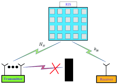
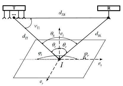
We consider a multiple-input single-output (MISO) system where a RIS is deployed to assist in the wireless communication from the transmitter to the receiver, as illustrated in Fig. 1. The transmitter is equipped with antennas, forming uniform linear array (ULA) while the user is equipped with a single antenna. In this scenario, the direct link between the transmitter and the receiver is blocked and the RIS is placed to provide a line-of-sight (LoS) link. The symmetric and regular RIS consists of reflective elements with rows and columns. The length of the single reflective element is denoted as and the width is denoted as . For simple notations, the RIS, the transmitter, and the receiver are denoted as I, T, and R, respectively.
Let us define as the channel between the transmitter and the RIS and as the channel between the receiver and the RIS. Using the amplitude and phase to represent the plural element, the channels are given by
| (1a) | |||
| (1b) | |||
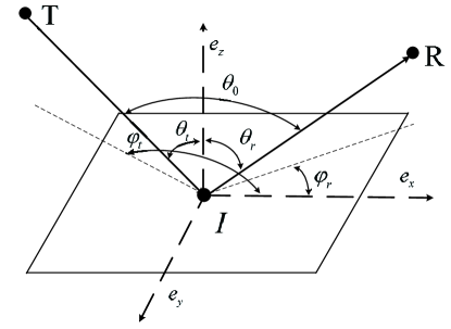
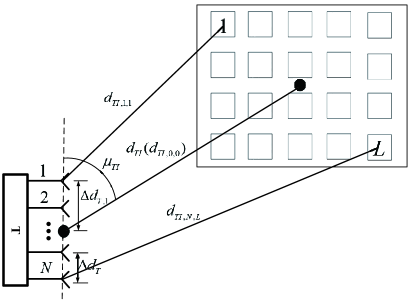
Note that, in the LoS link, the channel element is mainly related to the position relationships of the communication parties. For example, is determined by the distance from the -th antenna of T to the -th reflective element directly. The establishment of the geometric model between communication parties is important. After selecting a coordinate system and choosing the center point of the transmitter/receiver and the RIS as reference points, we represent the positions of T, I, and R by vector , , and respectively. Let denote the orientation of RIS. It is embodied in the elevation angle and the azimuth angle from T to I (denoted as and respectively), and the elevation angle and the azimuth angle from R to the I (denoted as and respectively). Tuning the orientation of the RIS purposely means adjusting the RIS-related angles ( , , and ) under geometric limitations, as illustrated in Fig. 2LABEL:sub@angle. When representing the position of the -th reflective element as , the centre point of the -th reflective element is chosen as the reference point. In the same manner, is used to denote the position of the -th antenna of . Fig. 2LABEL:sub@geometricalre depicts the positional relationship between the transmitter and the RIS. The geometrical relationship between the receiver and RIS is a simplification of it, thus omitted here. The position relationship between the elements and the RIS can be represented by a function as . The function is determined by the shape and size of the RIS. Similarly, , is a function determined by the direction of the ULA and the antenna spacing . Let denote the distance between the -th antenna and the reference point of T, given by
| (2) |
The distance from the -th antenna element to the -th RIS reflective element denoted by can be expressed as
| (3) |
It should be noticed that the rule of numbering sequence for antennas of T or elements of RIS is flexible and has no impact on the results we concerned.
In such a MISO system, the useful message is sent from T to R, which is normalized such that . Besides, they are multiplied by the beamforming vector with the power limit (). In order to combine with the physical path loss model hereinafter, accounts for the signal power in the linear domain at unit distance. The phase-shift matrix of the RIS, representing the properties of the RIS, is denoted by with . The elements in satisfy the condition . Equivalently, with is a real number.
The useful power of the received signal can be expressed by
| (4) |
II-B Physical and Electromagnetic Perspectives
| The characteristic impedance of the air | |
| Antenna gain of the transmitter | |
| Gain of the RIS | |
| Normalized power radiation pattern | |
| The complement angle of the DOA of the RIS at the transmitter | |
| The elevation angle from the reference point of the RIS to the transmitter | |
| The azimuth angle from the reference point of the RIS to the transmitter | |
| The elevation angle from the reference point of the RIS to the receiver | |
| The azimuth angle from the reference point of the RIS to the receiver | |
| The reflection coefficient of the RIS | |
| The aperture of the transmit antenna | |
| The aperture of the receive antenna | |
| The electric field intensity of the received signal |
In this subsection, we shall express the far-field amplitude gain and phase change of the RIS link from physical and electromagnetic perspectives. The parameters mentioned in this subsection are explained in Table I.
In far-field operation, the length/width of the RIS is much smaller than the distances of communication parties. According to the propagation principle of electromagnetic wave, the amplitude gains from different antenna elements to different RIS elements can be assumed the same.
| (5) |
This kind of approximation is named far-field amplitude approximation. Since it’s irrational to divide the effectiveness of RIS by or , the joint term is defined to represent the final amplitude gain from the transmitter to the receiver through individual reflective element of the RIS111The amplitude gain is actually a combination of channel gain and antenna gain..
Let us concretize . Referring to the the electric fields model described in [26], we have
| (6) |
Note that normalized power radiation pattern of the RIS is denoted as . The general normalized power radiation pattern of a single reflective element is in the form of
| (7a) | |||
| (7b) | |||
where 222The form can be used to match the normalized power radiation pattern of different unit cell and antenna designs with an appropriate [28].. Thus, turning a RIS at a fixed position impacts the amplitude gain . Fig. 2LABEL:sub@angle illustrates this problem. From above, the amplitude gain of the RIS is essentially a function of the position and orientation of the RIS.
We now turn the attention to the phase changes of the EM in the RIS link. The phase changes in the channel are equivalently written as
| (8a) | |||
| (8b) |
where is the carrier wavelength. Because the size of the reflective element and the antenna element separation is the same order or sub-order of the carrier wavelength, unlike amplitude gains, different phase changes can’t be assumed to be the same. However, in far-field operation, a tight distance approximation is suitable to apply, which is shown at the top of next page.
| (9a) | ||||
| (9b) | ||||
In the formula (9), represents the elevation/azimuth angle at the RIS from the -th transmitting antenna to the RIS. is the index number of columns of the -th element and is the index number of rows of the -th element. It needs to be mentioned that there are functions instead of functions in existing works[33, 34] due to the use of the supplementary angle. This kind of approximation is named far-field phase approximation.
In more details, approximation requires , similar to the traditional MIMO model[35]. Approximation is based on the formula in [26], which requires . We assume that the elevation/azimuth angles at the RIS from different antennas of the transmitter are identical, deriving approximation . This assumption is reasonable when . As a conclusion, The conditions of far-field approximationare summarized as follows
| (10) |
II-C Problem Formulation
From above, we can see that the channel gain and phase changes are both tightly related to the position and the orientation of the RIS. Some existing works, considering a fixed RIS, have designed the beamforming vector and phase-shift matrix jointly to improve the received power, namely the information achievable rate. In this paper, the position of the RIS and the orientation of the RIS are also under-determined variables, thus they can be utilized to further enhance the received power. Considering practical limitations, the joint optimization problem of RIS-assisted wireless communication is given by
| (11) |
where is a set that guarantees the EM to propagate from T to R through the RIS directly, which is specified by application environment. In more details, it is determined by the relative positional relationship of communication parties, obstacles and the orientation of RIS. can be expressed as . and are the minimum distance to guarantee the far-field condition, respectively. is the feasible area that the RIS can be fixed at. Herein, we denote the feasible set of as here. Without loss of generality, we assume that the antennas in T and R are omni-directional333If we consider the directional antenna, only placing the RIS in the main lobe is meaningful. Let denotes the area in the main lobe. Therefore, a new restriction should be added to ..
The problem () is a joint optimization of four variables, and it is challenging to solve directly. In the following, we devote to solving it by two phases. In the first phase, we assume is fixed, and the closed-form global optimal solutions of and as well as the optimal are proposed. In the second phase, based on the optimal solutions of the other three variables for a fixed , the problem become an unadulterated position optimizing problem (). Substituting the optimal position of () back to the optimal and and , which can be treated as functions of , the global optimal solutions of are all concretized444However, since we focus on far-field communications, the channels have been already approximated according to the far-field approximations in (). Therefore, the global optimal solutions of are near-optimal to the primal problem without approximations.. Note that, the sub-optimization problems in each phase can also be viewed as meaningful independent works.
III Optimal Strategy with a Fixed RIS
To decouple the solutions of , , with in problem , we consider a fixed RIS in this section. We find that the and are coupled with each other, but irrelevant to . In addition to derive optimal solutions of , and , we propose an anti-decay designing principle of manufacturing RIS for free-space THz communication.
III-A Optimal and
The solutions of and for the fixed RIS can be obtained using the iterative method proposed in [7]. However, it’s challenging to solve the joint optimization problem based on it. Herein, by exploiting the tightly coupled property of channel elements in the free space, we provide the analytic and optimal solutions of and .
For any given , it is widely known that maximum-ratio transmission (MRT) is the optimal transmit beamforming to maximize the received power [7], i.e.,
| (12) |
Applying the optimal , the received power can be expressed by
| (13) |
According to the far-field gain approximation and far-field phase approximation, the channel matrix can be rewritten as
| (14a) | |||
| (14b) | |||
| (14c) | |||
To maintain the uniform, we rewrite the as
| (15a) | |||
| (15b) | |||
After substituting them into (13), the new form of the received power is given by
| (16) |
with
| (17) |
Hence, the optimal to maximize the received power is
| (18) |
More clearly, considering the expressions of terms in (9), the optimal phase shift of reflective element is designed as
| (19a) | ||||
| (19b) | ||||
With the closed-form , the decoupled analytic solution of is given by
| (20) |
More clearly, considering the expressions of terms in (9), the -th element of is designed as
| (21) |
Under the proposed closed-form beamforming and phase shifts, the optimal received power becomes
| (22) |
As seen, the growth of the received power follows a scaling with the antenna elements and scaling with the reflective elements, which has been recognized in several recent works [27, 4].
The optimal received power can be expended as
| (23) |
where denotes the total area of the RIS. The formula (III-A) indicates an anti-decay designing principle of manufacturing RIS for mmWave/THz communication in free space. To maintain the the received power as the frequency of carrier wave increases, the RIS must manufactured according to the wavelength. In more details, there are two alternatives: One is when the area of total RIS is limited, the size of the reflective element should be in a fix proportional to the carrier wavelength. The other is when the area of reflective element is fixed, the number of the reflective elements is in a fixed inverse ratio to the carrier wavelength.
III-B Optimal Orientation of the RIS
As mentioned before, the orientation of the RIS can be adjusted to improve the received power via maximizing . The optimal value is denoted as hereinafter. Due to large distances between the RIS and communication parties in the far-field case, it’s reasonable to treat all reflective elements as the reference point of the RIS when calculating . As illustrated in Fig. 2LABEL:sub@angle, the problem of turning a RIS to reap the max gain is organized as
| (24) |
It is found that when , the objective function in (III-B) reaches the max value, denoted as , which is given by
| (25) |
From the above, the optimal orientation is just to make the RIS perform specular reflection, that is, the incident signal is mainly reflected towards the mirror direction . It is worth mentioned that this result in the MISO system is consistent with the counterpart in the SISO system[26].
IV Optimal position of the RIS
In this section, jointly with the optimal solutions of , , , we aim to study the optimal position of the RIS in problem .
As the objective function to optimize the position of the RIS, the maximum received power (III-A) is simplified as
| (26) |
According to (II-B), is a constant with no relationship to the position of the RIS. The position change of the RIS only impacts the value of and in this formula.
The position optimizing question is formulated as
| (27) |
where represents the feasible space to place RIS. In this section, we’ll study the property of optimal position in a two-dimensional plane, then extend it to arbitrarily three-dimensional space.
It is known that a three-dimensional feasible space can be fully split into parallel two-dimensional subspaces. Then, the problem is replaced by many parallel subproblems, where the position of the RIS is an two-dimensional variable. It is noted that the principle of splitting is flexible and has no influence to the final result.
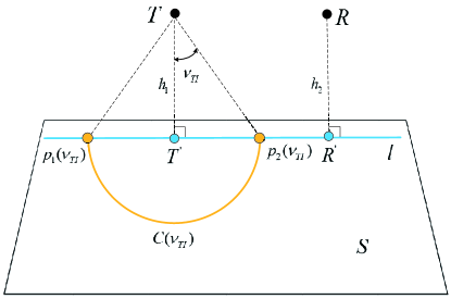
We start from not considering the constraints of placing RIS,. Then the parallel subproblems is to optimize the position of RIS on an infinite large plane, named S. Adequately, we consider the plane of S due to the symmetry. Hereinafter, the plane S represents the half plane. The scenario of finding optimal position on plane S is illustrated in Fig. 3. The points and represent the projection of T and R on plane S respectively. The line l denotes the line containing and on plane S. The term denotes the line segment whose endpoints are and . The term accounts for the half-line staring from and containing . By contrary, the half-line stars from and contains . The term is the intersection angle of and .
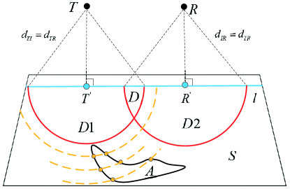
It is obvious that the values of and can uniquely determine a position of the RIS on plane S. The optimal problem is reformulated as:
| (28) |
where, represents possible unions of and . For a given , the feasible set of the RIS on plane S is a circle marked as . After excavating the quasi-convex property of , the following theorems are obtained.
Theorem 1
Proof 1
See Appendix A and Appendix B.
As illustrated in Fig. 4, we put forward a useful corollary for placing the RIS on an arbitrary two-dimensional area A.
Corollary 1
For an arbitrary closed feasible area A on the whole plane S when or SD when , the optimal position of the RIS is must on A’s boundary and the feasible part on line l.
Eventually, based on the fact that a three-dimensional space can be split to the parallel planes fully, we extend above corollaries to the feasible space . Similar to the two-dimensional case, a special space is defined as the forbidden space, whose cross section created by plane S are the area D. The following corollary is derived.
Corollary 2
For an arbitrary closed feasible space in the whole three-dimensional space when or in the three-dimensional space except the special space when , the optimal position of the RIS is must on the surface of 555Note that, due to the plane S is an arbitrary plane, the feasible part on line l can be avoided by selecting the plane S suitablely..
Remark 1
Note that the area D diminishes as the and becomes either larger or smaller. For most cases, the area D can be neglected or does not exist. Accordingly, for three-dimensional cases, the special space can be neglected or does not exist in most cases. Based on our proposed corollaries, the dimension of the area of interest can be reduced. Thus the computational complexity of any numeral algorithms can be reduced.
V Extensions and Discussions
V-A Extensions to the Existing of Direct Link
We consider adding a RIS to enhance the wireless communication in free space. Now, besides the RIS link, the direct link also exists. The direct channel can be expressed as
| (29) |
with
| (30) |
where is the distance from antenna to the receiver, . In this scenario, the received signal is a sum from two pathes, which is given by
| (31) |
The joint optimal Problem P1 is unchanged except replacing the objective function with . For this scenario, we also propose a closed-form phase shifts as follows.
| (32a) | ||||
| (32b) | ||||
where
| (33) |
Proof 2
See Appendix C.
Interestingly, compared to (19), only the term is polymeric in (32). It’ not hard to obtain the corresponding bemforming by using MRT, thus omitted here. With the solutions, the received power is expressed as
| (34) |
The derived results about the orientation and position of the RIS can also be extended to this scenario naturally. It is obvious that the optimal orientation of RIS is in accordance with the counterpart in Section III-B. The aforementioned conclusions of the optimal position of RIS has to be adjusted slightly. The analytic process is similar to that shown in Section IV. Differently, the plane S fitting in this scenario can’t be arbitrary anymore, and becomes a special plane where the ULA of the transmitter is perpendicular to it. While analysing in the same manner as the derivation in Appendix B, it is found that only the results under fixed is available due to the the existing of . Because when is fixed, is fixed, resulting in a certain value of . By this way, the is consistent with the objective function of Problem . However, the similar results don’t exist anymore when is fixed. Therefore, the theorems and corollaries in Section IV also hold by replacing area with area . Besides, for three-dimensional cases, a now space needs to be added where the optimal position may lies in. That is the feasible part on the plane consisting of the ULA and line l.
V-B Extension to UPA Cases
We have assumed the transmit antenna to be a ULA in system model. Actually, our work can be transplanted to uniform planar array (UPA) case seamlessly as long as the far-field condition is satisfied. The corresponding adjustment is to reformulate the distance approximations at the transmitter. In more details, we reformulate in (9) as
| (35) |
where denotes the columns of the UPA and denotes the index number of columns of antenna . denotes the rows of the UPA and denotes the index number of rows of antenna . denotes the unit two-dimensional interval in the UPA. and account for the elevation angle and the azimuth angle from the transmit antenna to the RIS at the transmitter side, respectively. Note that it is similar to the approximations at the RIS since they are both planar array. With the adjustment, our analysis is unchanged for UPA cases.
V-C General Beamforming and Phase Shifts
A main limitation of the aforementioned results for the joint optimization is that they are derived under far-field operation. In far-field operation, the channel gain is obtained by far-field amplitude approximation and far-field phase approximation. These approximations may be unreliable under near-field operation, when RIS is close to the transmitter or to the receiver or RIS has a large size. In order to extend application scenarios, we develop the proposed beamforming and phase shifts to both near-field and far-field cases and propose SVD-based solutions. According to (13), the received power with optimal is
| (36) |
where is the SVD version of and is the first column of . For , the equality holds when , where represents the first column of . However, due to the unit-modulus restriction of phase shifts, we perform a projection process to obtain a feasible solution. Our proposed phase shifts is given by
| (37) |
Then, the corresponding beamforming is expressed as
| (38) |
Remark 2
As shown in Section III, the channels can be seen as a rank-one unit-modulus matrix in far-filed cases. When applying (37), the proposed closed-form solutions for far-field cases can be derived equivalently. The phase shifts in (37) is actually a general form of (19). However, as the distances between communication parties become nearer or the RIS becomes larger, the inequality in (37) is more relax, degrading the effectiveness. Simulation results reveal that the proposed SVD-based solutions are effective in far-field operation and relative near-field operation (the distance is not close enough), but not in absolute near-field operation (the distance is very close).
VI Simulations and Discussions
Numerical simulations about RIS-assisted wireless communication in free space have been conducted. This section is further divided into three subsections. Subsection VI-A investigates the effectiveness of our proposed beamforming and phase shifts, compared with the received power upper bound as a performance benchmark. Subsection VI-B studies the received power with the position of RIS on a plane under direct link either blocked or existed. Then we show the advantages of RIS to assist in free-space mmWave/THz communication. Eventually, we verify the robustness of our proposed beamforming and phase shifts in Subsection VI-C. In default, the physical and electromagnetic parameters are listed in Table.II.
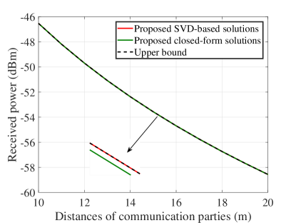
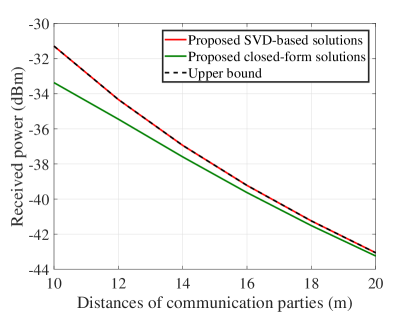
VI-A The Effectiveness of the Proposed Beamforming and Phase Shifts
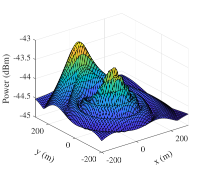
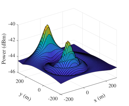
We have proposed two approaches for beamforming and phase shifts, one is the closed-form solutions ((19) and (20)), the other is SVD-based solutions ((37) and (38)). The effectiveness of them are demonstrated in Fig. 6. The geometric setups are illustrated in Figure. 5. Moreover, let . Via scaling the value of , both near-field and far-field operations can be included. The transmit/receive antennas are omnidirectional here, thus . As seen, when the size of the reflective element is small as , both the two proposed approaches achieve the limit performance, equal to the upper bound (V-C). When the size of the reflective element is large as , the proposed SVD-based method exceeds the proposed closed-form method, especially at short distances. But the computational complexity of proposed SVD-based method is higher. It is also found that the proposed SVD-based solutions still approach the upper bound (V-C). Note that, the distances shown in Fig. 6 are already in the near field of the RIS ( see [26]). Therefore, our proposed approaches are effective in far-field operation and even in relative near-field operation (the distance is not close enough). For the absolute near-field operation (the distance is very close), the traditional way of calculating the total gain of reflective elements may not be accuracy (see [27]), therefore we don’t consider here.
VI-B The Performance of RIS
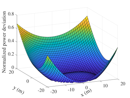
We investigate the performance of RIS by placing the reference point of RIS on a two-dimensional plane S. For a fixed RIS, the optimal strategy, including the proposed beamforming and phase shifts, the optimal orientation of RIS, is applied666It is worth mention that with the optimal orientation, the RIS and plane S are not coplanar.. The geometric setup can be referred in Fig. 3. Moreover, we set and the direction of ULA is perpendicular to plane S (for convenience of simulation but not necessary). The coordinate origins of plane S is selected as . The positive direction of X-axis is selected as and the Y-axis is determined correspondingly on plane S. Without loss of generality, we let .
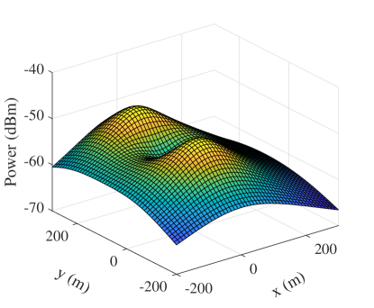
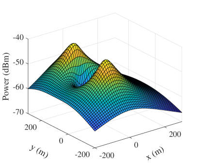
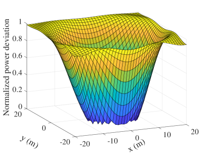
Fig. 7 reveals the received power versus the position of RIS on plane S via traversal grid when the direct link is blocked. As seen the optimal solution is near or and on line l, which is consistent with our analysis. Similarly, we investigate the received power for existing the direct link in Fig. 8. As seen, there are many ripples due to the balance of the RIS link and direct link to maximize the received power (34). In more details, they are determined by the antennas structure and DOAs of the RIS/receiver at the transmitter, which is given by (33). We also find that the amount of the ripples is half of the number of antennas at the transmitter. It is observed that the optimal solution is close to , and on line l, which is consistent with with our analysis. Moreover, the power at is obvious larger than that at due to the existence of direct link.
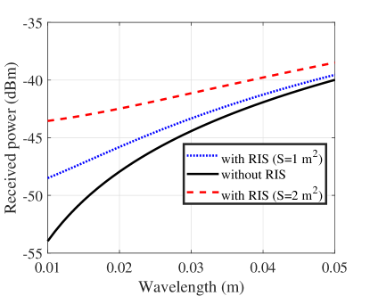
Fig. 9 illustrates the optimal received power versus the carrier wavelength. Moreover, we let and fix the RIS at on plane S. Note that the RIS in this figure satisfies the proposed anti-decay designing principle where . It is observed that, as the wavelength decreases, the optimal received power from direct link decays largely. But with the help of RIS link, the performance degradation is alleviated. Therefore, the RIS has absolute advantages to assist in free-space mmWave/THz communication.
VI-C The Robustness of Our Proposed Beamforming and Phase shifts
In practice, the obtained position of RIS may be obtained imperfectly due to the error of measurement or the mobility of the RIS. Therefore we demonstrates the robustness of our proposed solutions of beamforming and phase shifts in Fig. 10. The geometric setup is same to the last subsection, and the direct link is blocked. Assuming the known position of the RIS is (origin). According to it, the closed-form beamforming and phase shifts are derived, named the estimated solutions. Fig. 10 illustrates the normalized power deviation using estimated solutions versus the practical position of the RIS on plane S. The normalized power deviation is used to quantity the deviation of the received power, which is given by
| (39) |
where denotes the received power using estimated solutions and denotes the ideal optimal received power. It is found that the area for is large than . Therefore, our proposed solutions are strongly robust to the position perturbation of the RIS. Note that the performance of the proposed SVD-based solutions is consistent with the proposed closed-form solutions in the far-field operation, thus omitted here.
VII Conclusion
In this paper, comprehensive optimization of incorporating a RIS to MISO wireless communication in free space has been considered from electromagnetic and physical perspectives. The closed-form solutions of transmitter’s beamforming and phase shifts have been proposed and extended. Considering the general power radiation pattern, we have proved that the optimal orientation of the RIS is just to satisfy specular reflection. United with the above contributions, the position optimizing problem of placing a RIS has been studied. For most three-dimensional space to place the RIS, a substantial dimensionality reduction theory was provided. In simulation part, the proposed closed-form solutions of beamforming and phase shifts approach the power upper bound. Besides, the robustness in terms of position perturbation is verified. The simulation results indicate that adding a RIS is remarkable in mmWave/THz communication.
Appendix A Proof of Theorem. 1 ()
For any fixed , the orbit of feasible position is a circle on plane S. If is fixed, the value of is also certain. decreases from to along . is a decreasing function to , the max value of arrives at point . Therefore, for an arbitrarily position on the plane S, there must exists a position on the half-line with the same , at which the value of the objective function is equal or bigger. As a conclusion, the optimal position is must on the half-line . With the same manner, when starting from fixing , we obtain a conclusion that the optimal position is must on the half of the half-line . Therefore, on plane S, the optimal position of RIS is must on line segment .
Appendix B Proof of Theorem. 1 ()
Necessarily, we’ll exploit the quasi-convex property of . For convenient expression, we simplify as and denote as . To maximize the value of is equal to maximize the value of . Then the objective function can be written as
| (40) |
Wherein, the constant and , deducing from (III-B).
The derivation of , denoted as is given by
| (41) |
where,
| (42) |
Proof:
| (43) |
Because , determines whether is positive or negative.
| (44) |
So, is a quasi-convex (quasilinear) function for . ∎
Proof:
The condition for is
| (45) |
If the solution doesn’t exist, then is a quasi-convex (quasi-linear) function. If it exists, since , implies . The second derivative of is given by
| (46) |
Due to , whether is negative or positive is determined by . The expression of is further expressed as
| (47) |
wherein, is due to when (45) holds. results from the substitution of (45) and the expression of . Therefore, is a quasi-convex function for . ∎
As a conclusion, when , is a quasi-convex function for a fixed . Due to the symmetry of and in the function , it also holds that when , is a quasi-convex function for a fixed . Let D1 account for the area where and D2 account for the area where . The union set of D1 and D2 is denoted as D.
Eventually, based on the basic property of quasi-convex function (Section in [36]), extending Appendix A, we derive a conclusion for . For , on the area S-D, the optimal position is must on the line l. Note that it is the line l, not the line segment due to the discrepancy of monotonicity and quasi-convex property.
Appendix C Optimal Phase Shifts for Existing Direct Link
We already know the MRT is the optimal method to design beamforming for point to point communication. After applying MRT, the received power can be expressed as
| (48) |
where,
| (49a) | |||
| (49b) | |||
We equivalently represent as , which is given by
| (50) |
It indicates that, via changing , the amplitude can be an arbitrary value in the feasible set and the amplitude can be an arbitrary value in the feasible set .
We deduce the expression of further as follows.
| (53) |
where is due to and results from is a geometric progression. It is verified that the conditions of maximizing are and . The variable can achieve this requirement if and only if
| (54) |
References
- [1] T. J. Cui, M. Q. Qi, X. Wan, J. Zhao, and Q. Cheng, “Coding metamaterials, digital metamaterials and programmable metamaterials,” Light, Sci. Appl., vol. 3, no. 10, p. e218, 2014.
- [2] Huanhuan, Yang, Xiangyu, Cao, Fan, Jun, Gao, Shenheng, Xu, and M. and, “A programmable metasurface with dynamic polarization, scattering and focusing control.” Sci. Rep., vol. 6, no. 1, p. 129, 2016.
- [3] C. Liaskos, S. Nie, A. Tsioliaridou, A. Pitsillides, S. Ioannidis, and I. Akyildiz, “A new wireless communication paradigm through software-controlled metasurfaces,” IEEE Commun. Mag., vol. 56, no. 9, pp. 162–169, 2018.
- [4] Q. Wu and R. Zhang, “Towards smart and reconfigurable environment: Intelligent reflecting surface aided wireless network,” IEEE Commun. Mag., vol. 58, no. 1, pp. 106–112, 2020.
- [5] M. Di Renzo, K. Ntontin, J. Song, F. H. Danufane, X. Qian, F. Lazarakis, J. De Rosny, D.-T. Phan-Huy, O. Simeone, R. Zhang, M. Debbah, G. Lerosey, M. Fink, S. Tretyakov, and S. Shamai, “Reconfigurable intelligent surfaces vs. relaying: Differences, similarities, and performance comparison,” IEEE J. Select. Areas Commun., vol. 1, pp. 798–807, 2020.
- [6] M. Jung, W. Saad, M. Debbah, and C. S. Hong, “On the optimality of reconfigurable intelligent surfaces (RISs): Passive beamforming, modulation, and resource allocation,” IEEE Trans. Wireless Commun., vol. 20, no. 7, pp. 4347–4363, 2021.
- [7] Q. Wu and R. Zhang, “Intelligent reflecting surface enhanced wireless network: Joint active and passive beamforming design,” in IEEE Global Communications Conference, GLOBECOM 2018, Abu Dhabi, United Arab Emirates, December 9-13, 2018, 2018, pp. 1–6.
- [8] X. Yu, D. Xu, and R. Schober, “MISO wireless communication systems via intelligent reflecting surfaces : (invited paper),” in 2019 IEEE/CIC International Conference on Communications in China (ICCC), 2019, pp. 735–740.
- [9] W. Shi, X. Zhou, L. Jia, Y. Wu, F. Shu, and J. Wang, “Enhanced secure wireless information and power transfer via intelligent reflecting surface,” IEEE Commun. Lett., vol. 25, no. 4, pp. 1084–1088, 2021.
- [10] Y. Han, W. Tang, S. Jin, C. Wen, and X. Ma, “Large intelligent surface-assisted wireless communication exploiting statistical CSI,” IEEE Trans. Veh Technol., vol. 68, no. 8, pp. 8238–8242, 2019.
- [11] C. Pan, H. Ren, K. Wang, M. Elkashlan, A. Nallanathan, J. Wang, and L. Hanzo, “Intelligent reflecting surface aided MIMO broadcasting for simultaneous wireless information and power transfer,” IEEE J. Sel. Areas Commun., vol. 38, no. 8, pp. 1719–1734, 2020.
- [12] C. Pan, H. Ren, K. Wang, W. Xu, M. Elkashlan, A. Nallanathan, and L. Hanzo, “Multicell MIMO communications relying on intelligent reflecting surfaces,” IEEE Trans. Wireless Commun., vol. 19, no. 8, pp. 5218–5233, 2020.
- [13] W. Shi, J. Li, G. Xia, Y. Wang, X. Zhou, Y. Zhang, and F. Shu, “Secure multigroup multicast communication systems via intelligent reflecting surface,” China Commun., vol. 18, no. 3, pp. 39–51, 2021.
- [14] J. Ye, S. Guo, and M.-S. Alouini, “Joint reflecting and precoding designs for ser minimization in reconfigurable intelligent surfaces assisted MIMO systems,” IEEE Trans. Wireless Commun., vol. 19, no. 8, pp. 5561–5574, 2020.
- [15] M. Cui, G. Zhang, and R. Zhang, “Secure wireless communication via intelligent reflecting surface,” IEEE Wireless Commun. Lett, vol. 8, no. 5, pp. 1410–1414, 2019.
- [16] H. Shen, W. Xu, S. Gong, Z. He, and C. Zhao, “Secrecy rate maximization for intelligent reflecting surface assisted multi-antenna communications,” IEEE Commun. Lett., vol. 23, no. 9, pp. 1488–1492, 2019.
- [17] X. Zhou, S. Yan, Q. Wu, F. Shu, and D. W. K. Ng, “Intelligent reflecting surface (IRS)-aided covert wireless communications with delay constraint,” IEEE Trans. Wireless Commun., pp. 1–1, 2021.
- [18] F. Shu, Y. Teng, J. Li, M. Huang, W. Shi, J. Li, Y. Wu, and J. Wang, “Enhanced secrecy rate maximization for directional modulation networks via IRS,” IEEE Trans. Commun., pp. 1–1, 2021.
- [19] M. Jung, W. Saad, Y. Jang, G. Kong, and S. Choi, “Reliability analysis of large intelligent surfaces (LISs): Rate distribution and outage probability,” IEEE Wireless Commun. Lett., vol. 8, no. 6, pp. 1662–1666, 2019.
- [20] A. Taha, M. Alrabeiah, and A. Alkhateeb, “Enabling large intelligent surfaces with compressive sensing and deep learning,” IEEE Access., pp. 1–1, 2021.
- [21] Z. He and X. Yuan, “Cascaded channel estimation for large intelligent metasurface assisted massive MIMO,” IEEE Wireless Commun. Lett., vol. 9, no. 2, pp. 210–214, 2020.
- [22] Q. Wu and R. Zhang, “Beamforming optimization for wireless network aided by intelligent reflecting surface with discrete phase shifts,” IEEE Trans. Commun., vol. 68, no. 3, pp. 1838–1851, 2020.
- [23] S. Guo, S. Lv, H. Zhang, J. Ye, and P. Zhang, “Reflecting modulation,” IEEE J. Select. Areas Commun., vol. 38, no. 11, pp. 2548–2561, 2020.
- [24] Ö. Özdogan, E. Björnson, and E. G. Larsson, “Intelligent reflecting surfaces: Physics, propagation, and pathloss modeling,” IEEE Wireless Commun. Lett., vol. 9, no. 5, pp. 581–585, 2020.
- [25] S. W. Ellingson, “Path loss in reconfigurable intelligent surface-enabled channels,” CoRR, vol. abs/1912.06759, 2019. [Online]. Available: http://arxiv.org/abs/1912.06759
- [26] W. Tang, M. Z. Chen, X. Chen, J. Y. Dai, Y. Han, M. Di Renzo, Y. Zeng, S. Jin, Q. Cheng, and T. J. Cui, “Wireless communications with reconfigurable intelligent surface: Path loss modeling and experimental measurement,” IEEE Trans. Wireless Commun., vol. 20, no. 1, pp. 421–439, 2021.
- [27] E. Björnson and L. Sanguinetti, “Power scaling laws and near-field behaviors of massive MIMO and intelligent reflecting surfaces,” IEEE Open J. Commun. Soc., vol. 1, pp. 1306–1324, 2020.
- [28] W. L. Stutzman and G. A. Thiele, Antenna Theory and Design. New York : J. Wiley., 1997.
- [29] P. Mursia, F. Devoti, V. Sciancalepore, and X. Costa-Pérez, “RISe of flight: RIS-empowered UAV communications for robust and reliable air-to-ground networks,” IEEE Open J. Commun. Soc., vol. 2, pp. 1616–1629, 2021.
- [30] Y. Pan, K. Wang, C. Pan, H. Zhu, and J. Wang, “UAV-assisted and intelligent reflecting surfaces-supported terahertz communications,” IEEE Wireless Commun. Lett., vol. 10, no. 6, pp. 1256–1260, 2021.
- [31] E. N. Papasotiriou, A.-A. A. Boulogeorgos, A. Stratakou, and A. Alexiou, “Performance evaluation of reconfigurable intelligent surface assisted d-band wireless communication,” in 2020 IEEE 3rd 5G World Forum (5GWF), 2020, pp. 360–365.
- [32] J. He, H. Wymeersch, and M. Juntti, “Leveraging location information for RIS-aided mmwave MIMO communications,” IEEE Wireless Commun. Lett., vol. 10, no. 7, pp. 1380–1384, 2021.
- [33] A. Sayeed and J. Brady, “Beamspace MIMO for high-dimensional multiuser communication at millimeter-wave frequencies,” in 2013 IEEE Global Communications Conference (GLOBECOM), 2013, pp. 3679–3684.
- [34] A. M. Sayeed and N. Behdad, “Continuous aperture phased MIMO: A new architecture for optimum line-of-sight links,” in 2011 IEEE International Symposium on Antennas and Propagation (APSURSI), 2011, pp. 293–296.
- [35] A. Goldsmith, Wireless Communications. Cambridge University Press, 2005.
- [36] S. Boyd and L. Vandenberghe, Convex Optimization. Cambridge, U.K.: Cambridge Univ. Press, 2004.