Higher-order meniscus oscillations driven by flow-focusing leading to bubble pinch off and entrainment in a piezo acoustic inkjet nozzle
Abstract
The stability of high-end piezo-acoustic drop-on-demand (DOD) inkjet printing is sometimes compromised by the entrainment of an air bubble inside the ink channel. Here, bubble pinch-off from an acoustically driven meniscus is studied in an optically transparent DOD printhead as a function of the driving waveform. We show that bubble pinch-off follows from low-amplitude higher-order meniscus oscillations on top of the global high-amplitude meniscus motion that drives droplet formation. In a certain window of control parameters, phase inversion between the low and high frequency components leads to the enclosure of an air cavity and bubble pinch-off. Although phenomenologically similar, bubble pinch-off is not a result of capillary wave interaction such as observed in drop impact on a liquid pool. Instead, we reveal geometrical flow focusing as the mechanism through which at first, an outward jet is formed on the retracted concave meniscus. When the subsequent high-frequency pressure wave hits the now toroidal-shaped meniscus, it accelerates the toroidal ring outward resulting in the formation of an air cavity that can pinch off. The critical control parameters for pinch off are the pulse timing and amplitude. To cure the bubble entrainment problem, the threshold for bubble pinch-off can be increased by suppressing the high frequency acoustic waves through appropriate waveform design. The present work therefore aids the improvement of the stability of inkjet printers through a physical understanding of meniscus instabilities.
I Introduction
Piezo inkjet printing is an accurate and contactless method to deposit ink droplets on a substrate Basaran (2002); Wijshoff (2010); Hoath (2015); Lohse (2021). Droplets are formed on-demand from a nozzle by actuating a piezoelectric element. The piezo deforms the channel wall upon electrical stimulation, resulting in acoustic pressure waves that jet the ink out of the nozzle Fraters et al. (2020). Piezo inkjet printing is used in high-end industrial printers for on-demand personalized printing of documents, graphic art, and packaging. The main reason being its high reliability, high print quality, and its compatibility with a wide range of inks. The aforementioned properties make piezo inkjet printing also an excellent technique for several emerging additive manufacturing applications such as printing electronics Majee et al. (2016, 2017); Eshkalak et al. (2017); Vilardell et al. (2013); Moya et al. (2017); Eggenhuisen et al. (2015); Hashmi et al. (2015); Shimoda et al. (2003); Jiang et al. (2017), pharmaceutics Daly et al. (2015), biomaterials Simaite et al. (2016); Hewes et al. (2017); Nakamura et al. (2005); Villar et al. (2013), and even for the lubrication of ball bearings van der Kruk et al. (2019).
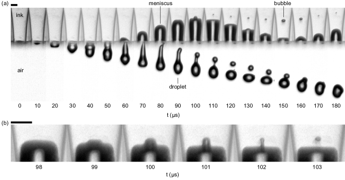
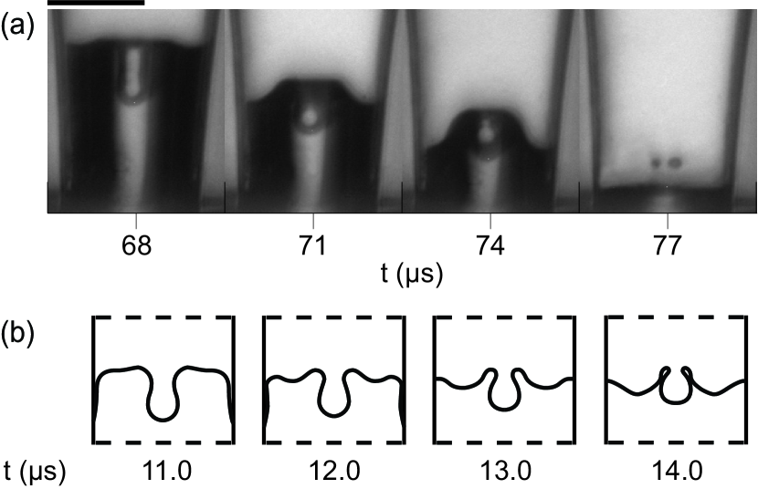
Although piezo inkjet printing is a highly reliable droplet deposition technique, the droplet formation process is sometimes compromised by the entrainment of an air bubble de Jong et al. (2006a, b); Jeurissen et al. (2008, 2009); Lee et al. (2009); Kim et al. (2009); Jeurissen et al. (2011); van der Bos et al. (2011b); Fraters et al. (2019a, b). The entrained air bubble disturbs or even stops the jetting process and thereby dramatically reduces the printing quality and reliability. Previously, several mechanisms have been identified by which bubbles can be entrained in the ink channel. First, on the nozzle plate at the nozzle exit, dirt particles or an ink layer can trigger bubble entrainment by disturbing the jetting process at the nozzle exit de Jong et al. (2006a). Second, a dirt particle in the ink can trigger bubble nucleation upon its interaction with the oscillating meniscus interface and, third, a bubble can nucleate on the particle through cavitation inception in the rarefaction pressure wave Fraters et al. (2019b). However, bubbles can also be entrained in the absence of dirt particles or an ink layer, i.e., by yet another physical mechanism. Figure 1 shows such a bubble pinch-off and entrainment event that was observed in a squeeze type piezo inkjet printhead with a 70-µm diameter optically transparent nozzle exit (Microdrop Technologies GmbH, Autodrop Pipette AD-K-501), driven by a rectangular push-pull pulse (amplitude: 150 V, width: 30 µs). First, a droplet is ejected, and subsequently, the meniscus retracts back into the nozzle and a bubble pinches off when the meniscus motion reverses from its inward motion to an outward motion, away from the ink channel. The bubble pinch-off event is shown in more detail in Fig. 1(b). The figure shows that the central region of the meniscus moves inward while the outer region of the meniscus moves outward. As a result, an air cavity forms that eventually closes, thereby pinching off an air bubble.
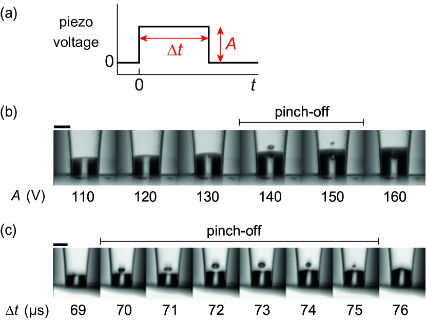
Bubble pinch-off as shown in Fig. 1 was found to occur only within certain windows of the piezo driving conditions. This is illustrated in Fig. 2, where two examples of a bubble pinch-off window are given for a rectangular pull-push pulse with amplitude and width (Fig. 2(a)). In the first example in Fig. 2(b), the pulse amplitude was varied with all other parameters fixed. A window of bubble pinch-off was observed between pulse amplitudes of 140 V and 150 V. Given the nature of meniscus instabilities, meaning that the growth time shortens and the oscillation amplitude increases with increasing acceleration Rayleigh (1883); Taylor (1950); Faraday (1831), it was expected that bubble pinch-off would always occur above a certain threshold amplitude. Surprisingly, no bubble pinch-off was observed at amplitudes larger than 160 V. In the second example, see Fig. 2(c), the pulse width was varied. Bubble pinch-off was observed between pulse widths of 70 µs and 75 µs. The bubble size initially increases and then decreases, with a maximum radius between 72 µs and 73 µs.
An oscillating meniscus can be destabilized by several mechanisms, including the classical Rayleigh-Taylor instability Rayleigh (1883); Taylor (1950); van der Meulen et al. (2020) and the parametrically driven meniscus instability Faraday (1831); Tence et al. . A Rayleigh-Taylor instability grows on a flat interface between two fluids with different density, i.e., in this particular case the ink and air. The two fluids are accelerated at a rate high enough for the inertial forces to overcome the restoring surface tension. The parametrically driven meniscus instability grows on an initially flat meniscus at the subharmonic of the frequency at which the meniscus is driven (period doubling). The meniscus can also be destabilized at intermediate Ohnesorge number by an inhomogeneous velocity field at the meniscus due to the finite transport time of viscous-drag-induced vorticity from the wall to the center of the nozzle Chen and Basaran (2002). Furthermore, the meniscus can be deformed by geometrical flow focusing when a pressure wave hits a concave meniscus Antkowiak et al. (2007); Peters et al. (2013); Gordillo et al. (2020). Finally, meniscus destabilization and resulting bubble pinch-off can originate from the interaction of capillary waves at the gas-liquid interface. In fact, there is a remarkable similarity between the bubble entrainment phenomenon in Figs. 1 and 2, and in particular the window of bubble entrainment, with bubble pinch-off during crater collapse in drop impact and that during bubble bursting at the surface of a liquid pool Oguz and Prosperetti (1990); Pumphrey and Elmore (1990); Thoroddsen et al. (2018); Sleutel et al. ; Duchemin et al. (2002); Gordillo and Rodríguez-Rodríguez (2019). In these cases, bubble entrainment is a result of capillary waves traveling down the cavity that then interact at the base of the cavity leading to the pinch-off of a bubble. Bubble pinch-off has been shown to require perfect timing of capillary wave interaction and it thereby depends on both the amplitude and the overal shape of the cavity Oguz and Prosperetti (1990); Sleutel et al. ; Gordillo and Rodríguez-Rodríguez (2019).
The aim of the present study is to find the underlying physical mechanisms that drive bubble pinch-off and entrainment as observed in Figs. 1 and 2, and to gain fundamental physical insight into the stability of an acoustically driven meniscus. To that end, after describing the methods for both the experiments and numerics in Section II, the meniscus and bubble dynamics shown in Fig. 1 are analyzed in more detail by tracking the meniscus position over time (Section III). The acoustic driving of the meniscus by the piezo actuator is further characterized by measuring the ring-down piezosignal. Then the meniscus dynamics of two additional experiments is analyzed to identify the process during which the inner and and outer region of the meniscus develop their destabilizing out-of-phase motion. Finally, the mechanisms that drive the development of this out-of-phase motion are identified using numerical simulations with the boundary integral (BI) method Peters et al. (2013). The paper ends with conclusions (section IV).
II Experimental and numerical methods
II.1 Printhead and ink
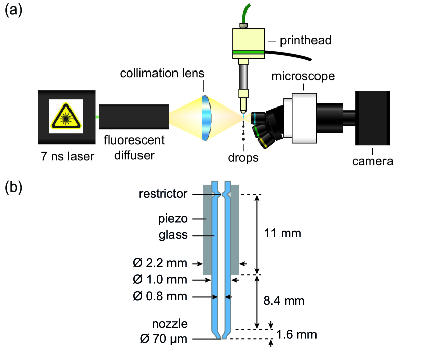
A 70 µm nozzle diameter Autodrop Pipette from Microdrop Technologies GmbH (AD-K-501 and AD-H-501) was used, see Fig. 3(a). Figure 3(b) shows the approximate inner dimensions of the functional acoustic part of the printhead. More details about this type of printhead can be found in refs. Dijksman (1984, 1998).
A 4:1 (v/v) mixture of water with glycerol (Sigma-Aldrich, G9012, 1,2,3-Propanetriol, 99.5%) was used as a model ink. All experiments were performed at room temperature. The density, viscosity, and surface tension were taken from literature to be 1050 kg/m3, 2.1 mPas, and 71 mN/m, respectively Segur and Oberstar (1951); Association (1963). The model ink was supplied from a plastic syringe to the top of the Autodrop Pipette holder via flexible plastic PEEK tubing (Upchurch Scientific), and the meniscus was positioned at the nozzle exit by manually adjusting the piston of the syringe.
II.2 Imaging setup
Bubble pinch-off was recorded using a stroboscopic imaging setup, see Fig. 3(a). The microscope (Olympus) had a 5 objective (LMPLFLN5x), a tube lens (U-TLU), and a high-resolution CCD camera (Lumenera, Lw135m, 13921040 pixels, 4.65 µm pixel size). The resulting optical resolution was 0.93 µm/pixel. The images captured by the camera were saved by custom-made software on a Personal Computer (PC) programmed in the graphical programming language Labview (National Instruments).
The tip of the Autodrop Pipette was illuminated by incoherent 8 ns illumination pulses with a wavelength of 577 nm from a Laser-Induced Fluorescence (iLIF) system van der Bos et al. (2011a). The iLIF system consisted of a pulsed laser (Quantel EverGreen, dual cavity Nd:YAG, \textlambda= 532 nm, 7 ns), a fluorescent plate embedded in a highly efficient diffuser (Lavision, part nr. 1108417 and 1003144), and a lens to condense the light pulses onto the imaging plane of the microscope.
II.3 Measurement procedure
A programmable pulse-delay generator (Berkeley Nucleonics Corp., BNC 575) triggered the laser, the camera, and the printhead actuation system with nanosecond precision. The jetting process was kept reproducible by jetting the entrained bubble outwards after each bubble pinch-off event. To do so, the piezo was actuated by rectangular pulses from two arbitrary waveform generators: one waveform generator (Agilent 33220A, 20 MHz, 14 bit, 50 MS/s) produced one high-amplitude pulse to entrain an air bubble, and the other waveform generator (Wavetek 195, 16 MHz, 12 bit, 40 MS/s) produced successively 49 low amplitude pulses to jet the entrained air bubbles out of the nozzle. For every actuation cycle, a custom-made Labview program captured one image during the high-amplitude piezo actuation pulse. The timing of image exposure was controlled by varying the delay of the laser flash with respect to the start of the piezo driving pulse. The delay was varied over a range from 0 µs to 200 µs with steps of 1 µs to capture the complete drop formation and bubble pinch-off process. A laboratory amplifier (Falco System WMA-300, 5 MHz, 2000 V/µs) amplified the pulses from the waveform generators by a factor of 50. Given the 5 MHz amplifier bandwidth, the rise- and fall time of the rectangular pulses was 0.2 µs. The rectangular piezo driving pulses had an amplitude between 0 V and 160 V, and the printhead could be driven in either the push-pull mode or pull-push mode by switching the polarity of the electrical connections at the printhead. With the complete system, droplets were produced with diameters in the range of 70 µm to 100 µm, corresponding to volumes of 180 pL to 520 pL, and droplet velocities in the range of 1 to 3 m s-1.
II.4 Image analysis
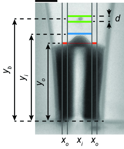
The motion of the meniscus and that of the bubble were tracked as a function of time. First the contrast in each image was enhanced using ImageJ (http://imagej.nih.gov/ij) by subtracting the original image from the image taken at = 0 µs, and by adding the inverted result to the original image. Second, the edges of the meniscus and bubble were detected using a script programmed in Python (Python Software Foundation, https://www.python.org/). The script applied a Scikit-Image Canny Edge Detector to each image, extracted the edges of interest, and calculated its positions. The meniscus was separated in an inner and outer region to quantify the meniscus shape deformation, see Fig. 4. The inner region was chosen such that it always confined the bubble, and had a width of 0.6 times the nozzle diameter. The outer region was set to a width of 0.9 times the nozzle diameter. The position of the outer region of the meniscus was the average position of the detected edge in that region. The position of the inner region of the meniscus was the maximum or minimum position of the detected edge in that region depending on whether it had a concave or convex shape, respectively. When a bubble was present, its center position and diameter were determined. The bubble diameter was always measured in axial direction to minimize a potential error in the bubble diameter due to the refraction of light at the cylindrical walls of the glass nozzle that can deform the image. The time-dependent positions , , and were filtered to extract the amplitudes and dynamics of the low- and high-frequency components of the meniscus motion.
II.5 Piezo eigenfrequency characterization through ring-down measurements
To characterize the resonance behavior of the piezo, the ring-down of the piezo was measured using a piezo sensing technique described in refs. de Jong et al. (2006a); Wijshoff (2010). The piezo was driven using an electrical pulse. Subsequently, when the driving voltage dropped below 1 V, the piezo contacts were connected automatically to an oscilloscope that recorded the ring-down voltage-oscillations of the piezo giving its characteristic resonance frequency.
II.6 Boundary integral simulations
To study the bubble pinch-off process and the underlying physical mechanisms in greater detail, boundary integral (BI) simulations were performed Peters et al. (2013). The utilized BI code is axisymmetric, and assumes irrotational, incompressible, and inviscid flow Ouz and Prosperetti (1993); Power and Wrobel (1995); Bergmann et al. (2009); Gekle et al. (2009). In essence, the unsteady Bernoulli equation:
| (1) |
is time integrated as described in Peters et al. (2013). In above equation, is the flow potential, the pressure variation, the curvature, and and the liquid surface tension and density, respectively. Owing to the micron sized meniscus, we neglect gravity. The inviscid assumption is appropriate here as in the experiments it was observed that the meniscus shape deformation is the largest at low viscosity, and decreases as the ink viscosity increases. The numerical setup consisted of a nozzle wall (solid boundary) and a meniscus (free boundary). The flow in the nozzle was driven by applying a stream velocity boundary condition to the nodes at the entrance of the nozzle.
Two methods were used sequentially to describe the contact line dynamics of the meniscus; a fixed contact line, and a moving contact line based on contact angle hysteresis with a receding contact angle and an advancing contact angle . Combining these two methods provided a good balance between approximating the experimentally observed meniscus motion and preventing numerical instabilities. These occurred when the distance between the free boundary and solid boundary became too small. At the start of each simulation the contact line was kept pinned. If during this first time period one of the nodes of the meniscus came within a distance from the wall that would cause numerical instability, the meniscus between that node and the contact line was cut off, and a new contact line was created near this node. This intervention did not have a significant effect on the bubble pinch-off phenomena in the simulations. Once the contact angle became larger than , the moving contact line method was initiated. This method keeps the contact line pinned for ; moves the contact line to if , and moves the contact line to when . and were set to the maximum angle away from 90∘ for which the meniscus motion near the wall remained stable during the simulations, i.e. = 72∘ and = 108∘. At larger angles away from 90∘ numerical instabilities would develop on the meniscus because of the too small distance between the free boundary and the solid boundary, as before.
III Results & discussion
III.1 Meniscus and bubble dynamics
The data shown in Fig. 1 are now analyzed in more detail. Figure 5(a) shows the position of the outer and inner region of the meniscus (, ) and that of the bubble () as a function of time. Note that just before pinch-off a phase difference develops between the inner and outer region of the meniscus eventually leading to phase inversion. This is the crucial opposing motion between the central cavity and the outer region of the meniscus that leads to bubble pinch-off, as was observed in Fig. 1(b). The process that is responsible for this phase difference is analyzed in Section III.3. Also note in Fig. 5(a) that both the meniscus position curve and the bubble position curve have a high-amplitude low-frequency motion of the order of 10 kHz (100 µs period) with superimposed a low-amplitude high-frequency motion of the order of 100 kHz (10 µs period). The low-frequency motion of the meniscus and bubble are indicated by the dashed curve and by the dash-dotted curve, respectively.
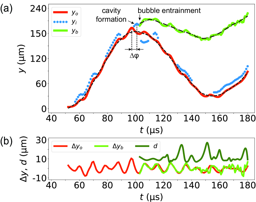
The high-frequency component in the meniscus motion and that of the bubble motion are plotted in Fig. 5(b). In addition, in Fig. 5(b) the bubble diameter is plotted as a function of time. The bubble equilibrium radius was 5 1 µm, which corresponds to a Minnaert eigenfrequency Minnaert (1933) of approximately 600 kHz. As this is much higher than the observed bubble oscillation frequency of 100 kHz, the radial dynamics of the bubble was considered to oscillate in phase with that of the acoustic pressure waves inside the ink channel Leighton (1994). Therefore, the bubble radius directly represents the channel acoustics, i.e. the maximum in bubble radius corresponds to a minimum pressure, and vice versa. Note in Fig 5(b) that the bubble diameter, the bubble position, and the meniscus position all oscillate at a frequency of 105 5 kHz. Also note that the meniscus and bubble are moving inward around the time that the bubble diameter is maximum (pressure minimum), while the meniscus and bubble start moving outward when the bubble diameter is minimum (pressure maximum). Thus, the meniscus and the bubble are driven by the same high-frequency pressure waves, and not by their individual eigenmodes.
III.2 Acoustic driving by the piezo
To determine whether the piezo actuator is the origin of the high-frequency pressure oscillations, the eigenmodes of the piezo were characterized by measuring the ring-down signal of the piezo for an empty ink channel. The piezo was first actuated using a pull-push pulse with an amplitude of 10 V, a FWHM pulse width of 72 µs, and a rise and fall time of 1 µs, see Fig. 6(a). The ring-down signal and its Fourier spectrum are plotted in Fig. 6(b) and 6(c). Indeed, in the ring-down signal the same 105 kHz high-frequency component was present as in the meniscus motion, bubble motion, and radial dynamics in Fig. 5(b). The piezo eigenmode frequencies were calculated from its dimensions (Fig. 3) and the speed of sound in piezoceramic (4000 m/s) to be 111 12 kHz in longitudinal direction and 3.4 0.1 MHz in radial direction APC International, Ltd (2011); APC International, Ltd. . Thus, the 105 kHz high-frequency component in the piezo ring-down signal originated from the longitudinal resonance mode of the piezo, and the pressure waves produced by this resonance mode drive the high-frequency motion of the meniscus in the nozzle. Indeed, when the high-frequency component is suppressed by using a of 9 µs, see Fig. 6(b) and 6(c), also the high-frequency motion of the meniscus is suppressed, see Fig. 6(d).
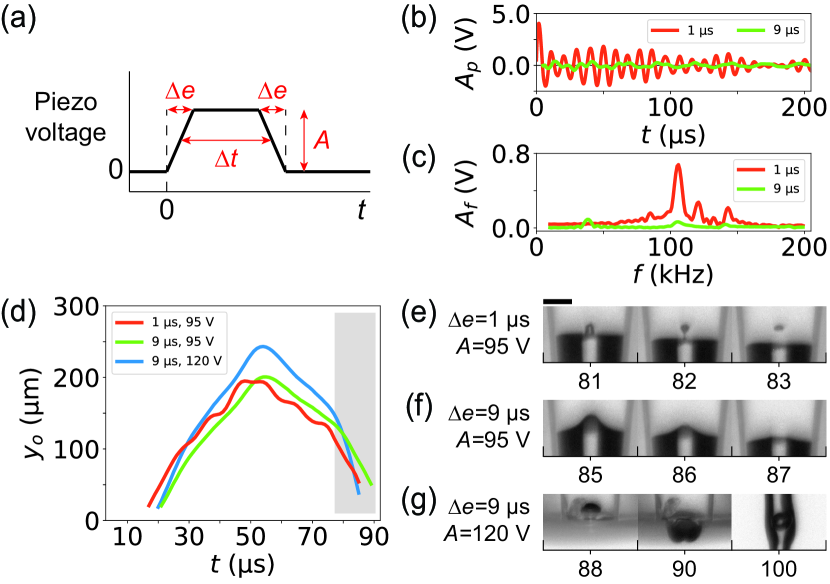
Notably, the absence of the 105 kHz high-frequency pressure waves also prevents bubble pinch-off, see Fig. 6(f) in comparison to Fig. 6(e). In the experiment shown in Fig. 6(f) an air cavity was still formed, but it did not pinch-off a bubble. This cavity could be forced to pinch-off in the same way as before, but at a different meniscus position and time, by increasing the amplitude of the piezo driving to 120 V, see Fig. 6(g). Thus, suppressing the high-frequency pressure waves effectively increased the threshold for bubble pinch-off from 95 V to 120 V. In other words, the high-frequency pressure waves from the longitudinal resonance mode of the piezo promote bubble pinch-off and through suppression of the 105 kHz waves, the driving amplitude can be increased allowing for stable inkjet printing at a higher droplet velocity.
III.3 Meniscus shape deformation process
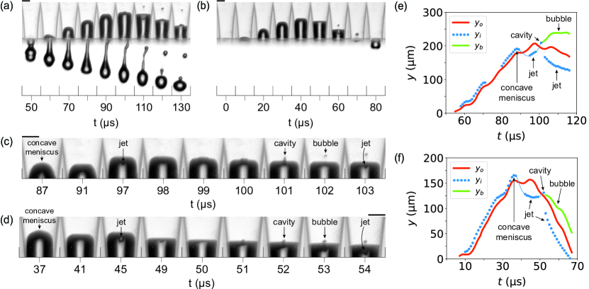
Now that the driving mechanisms of the meniscus are identified, next, the process responsible for the development of the phase difference between the inner and outer region of meniscus, eventually leading to phase inversion and bubble pinch-off, can be identified. The phase difference (Fig. 5(a)) develops through the meniscus shape deformation process that can be observed in Fig 7: it develops by jet formation at a concave meniscus. The universality of the meniscus shape deformation process prior to bubble pinch-off is demonstrated in Fig. 7 by its presence in two bubble pinch-off experiments with entirely different driving conditions, namely, with piezo driving pulses with opposite polarity. In the first experiment the piezo was actuated using a rectangular push-pull pulse (= 160 V, = 30 µs). A bubble was entrained after droplet formation, and it remained inside the nozzle, see Fig. 7(a). In the second experiment the piezo was actuated using a rectangular pull-push pulse ( = 150 V, = 30 µs). In contrast to the first experiment, a bubble was entrained before droplet formation, and it was ejected with the droplet shortly after entrainment, see Fig. 7(b). Despite the large differences between the two experiments, the image sequences and graphs in Fig. 7(c-f) show that the meniscus shape deformation process is qualitatively the same for the two experiments. Initially, upon retraction, the meniscus has a concave shape. Then, during the advancing of the meniscus, a small liquid jet is formed in outward direction. Later, this jet recoils back inward, while the outer region of the meniscus is forced to move outward again, in the opposite direction of the movement of the jet. Similar to the experiment in Fig. 1, the opposing motion of the outer and inner region of the meniscus leads to the formation and closure of a cavity, and thereby to the pinch-off of a bubble. Thus, phase inversion between the inner and outer region of the meniscus is a consequence of jet formation at the central part of the concave meniscus.
III.4 Jet formation mechanism
From literature it is known that when a pressure wave propels a concave-shaped meniscus forward, a jet forms due to geometrical focusing of the flow at the meniscus due to an inhomogeneous pressure gradient field along the meniscus Peters et al. (2013); Gordillo et al. (2020). The pressure gradient and resulting velocity are larger at the center of a concave meniscus than at its edge, see also ref. Antkowiak et al. (2007). Thus, in the inkjet nozzle, first, the inward motion of ink results in a concave shaped meniscus, then a first outward acceleration creates a phase difference between the inner and outer region of the meniscus by the formation of a central outward-moving liquid jet, and, finally, a well-timed second outward acceleration enhances this phase difference by the formation of a toroidal outward-moving liquid jet. The central liquid jet recoils inward and forms an air cavity that is enclosed by the toroidal outward-moving liquid jet, and as a consequence, a bubble pinches off.
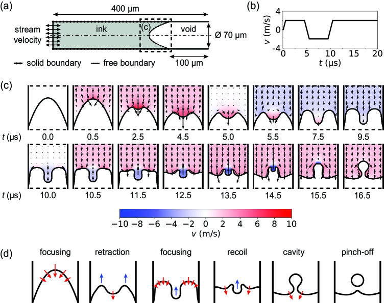
To further demonstrate the details of the proposed pinch-off mechanism, numerical simulations were performed using the boundary integral (BI) method. The results are shown in Fig. 8. The geometry of the numerical setup in Fig. 8(a), and the stream velocity boundary condition in Fig. 8(b), were chosen such that they follow the experimental conditions, i.e., the nozzle diameter and the 110 kHz oscillations that were identified to drive bubble pinch off. The initial meniscus shape (Fig. 8(c)) together with the imposed amplitude of the 110 kHz velocity boundary condition (Fig. 8(b) were varied and, as in the experiments, only for highly specific combinations of the two, the meniscus shape deformation process was developing toward bubble pinch-off. A simulation result is shown in Fig. 8(c). The figure reveals the amplitude and the direction of the ink velocity, and demonstrates how the velocity field inhomogeneity and the focusing of the flow at the concave part of the meniscus drive jet formation. Moreover, Fig. 8(c) highlights the opposing motion between the central jet and the toroidal jet, and shows in detail how this opposing motion leads to the formation of a cavity that closes and pinches off a bubble. The main steps in this process, which were discussed in detail before, are now schematically summarized in Fig. 8(d): a central jet forms at the concave meniscus during the first outward acceleration. Then, a toroidal jet forms at the concave meniscus around the central jet during the second outward acceleration. The recoiling central jet forms a cavity, and the progressing toroidal jet encloses this cavity, with bubble pinch-off as a result.
Note that even though the boundary integral simulations are incompressible, we observe the same meniscus deformation process as in the experiments suggesting that the meniscus shape deformation process responsible for bubble pinch off does not necessarily require acoustics, but that a certain unbalance between the capillary and inertial time scales is sufficient. Indeed, the capillary time scale (, with the nozzle radius) for the present inkjet nozzle is approx. 24 s whereas the inertial timescale is of the order of 1 s, i.e., set by the rise and fall time of in Fig. 8(b). Furthermore, from the input velocity boundary condition and Eq. 1 the dynamic driving pressure in the BI simulations can be calculated, as follows: , with and the pressure contributions from acceleration and inertia, respectively. The magnitude of is directly estimated from as 8 kPa. The magnitude of can be estimated as 1.4 to 12 bar, with the velocity variation (4 m/s) over time (1 s, see Fig. 8(b)) and a length scale between the nozzle radius (35 m) and the fluid-filled domain (300 m, see Fig. 8a). Note that since the BI simulations are incompressible, these dynamic pressure fluctuations are to be compared with acoustic pressure fluctuations in the experiment. The order of magnitude of the dynamic driving pressure amplitude is in line with values reported for the acoustic driving pressure in inkjet printing Wijshoff (2010); Fraters et al. (2019b) which once more shows that acoustic wave propagation is not required for the observed bubble pinch-off phenomenon and that it is mainly a flow-dominated process.
III.5 The bubble pinch-off window
Using the acquired knowledge on the underlying physics of the bubble pinch-off phenomenon studied in this work, we now qualitatively explain the observed parameter windows of bubble pinch-off in Fig. 2. In Fig. 2(b) the pulse width was fixed and the amplitude was varied. At an amplitude of 130 V and lower, the velocity difference between the recoiling central jet and the progressing toroidal jet was not high enough to form a sufficiently deep cavity at the right moment in time and to enclose this cavity. At an amplitude of 160 V the central jet had such a length and inertia that it was too slow to recoil before the toroidal jet reached the central axis. As a result, the toroidal jet enclosed the base of the central jet, which in multiple experiments and simulations has been observed to result in the formation of a toroidal bubble such as shown experimentally in Fig. 9(a) and from a BI simulation in Fig. 9(b).
In Fig. 2(c) the amplitude was fixed, and the pulse width was varied. In other words, the control parameter in these experiments was the timing of the outward acceleration of the meniscus by the falling edge of the piezo driving pulse. In the experiments shown in Fig. 2(c) the central jet had already been formed before the falling edge of the pulse. At the different times of meniscus acceleration, the meniscus shape was different, and thus the toroidal jet formation process was different. At = 69 µs the acceleration was too early, i.e. the central jet was not able to develop sufficient opposing motion with respect to the toroidal jet because of its early formation. At = 76 µs the acceleration was too late, i.e. the meniscus was propelled outwards while the cavity was already present, thus, the central cavity was propelled outward faster than the outer region of the meniscus.
Despite the acquired knowledge on the underlying physics of the bubble pinch-off mechanism, it remains difficult to predict where exactly in the piezo driving parameter space bubble pinch-off will occur, as is also the case for bubble pinch-off after drop impact on a liquid pool Oguz and Prosperetti (1990); Sleutel et al. . The two main reasons are the sensitivity of the mechanism to the operating conditions and the unavailability of information about the exact printhead configuration and its detailed acoustic properties. As a practical guideline, however, bubble pinch-off can be suppressed with relative ease by suppressing the high-frequency component in the acoustics through the edge duration of the piezo driving pulse. Another simple method, which was not studied here, is to damp out the meniscus shape deformations by increasing the ink viscosity. However, this requires higher driving amplitudes to produce droplets at equal velocity and reduces the universal applicability of the technique. The role of ink viscosity on meniscus deformations due to flow focusing in an inkjet nozzle will be part of future work.
IV Conclusions
An acoustically driven meniscus in a piezo inkjet nozzle can pinch-off a bubble under specific driving conditions. Pinch-off is the result of the closure of a central air cavity in the meniscus that forms due to opposing motion between a central region and an outer region of the meniscus. The opposing motion between the central region and outer region of the meniscus is the result of jet formation at the concave meniscus. Jet formation is driven by flow focusing, i.e., due to the inhomogeneous pressure gradient field along the meniscus, as was confirmed by boundary integral simulations. The process that is responsible for the bubble pinch-off can be summarized as follows: the meniscus gains a concave shape due to inward motion. Subsequently, a first outward acceleration produces a central jet at the concave meniscus. A well-timed second outward acceleration produces a toroidal jet at the concave meniscus around the central jet. The recoiling central jet forms a central air cavity while the progressing toroidal jet encloses this air cavity. Eventually, this leads to pinch-off of an air bubble. These results gain fundamental understanding of the stability of an acoustically driven meniscus in an inkjet printhead and thereby provide ways to increase the stability of inkjet printing. The results from the incompressible boundary integral simulations suggest that bubble pinch off requires a certain unbalance between the capillary and inertial time scales and that it is mainly flow-driven and does thereby not necessarily require acoustics. Future work will focus on further elucidating the role of acoustics and liquid viscosity on bubble pinch off and entrainment.
Acknowledgements.
This work is part of the research program ”High Tech Systems and Materials” (HTSM) with project number 12802, and part of the Industrial Partnership Program number i43, of the Dutch Technology Foundation (STW) and the Foundation for Fundamental Research on Matter (FOM), which are part of the Netherlands Organisation for Scientific Research (NWO). The research was co-financed by Canon Production Printing Netherlands B.V., University of Twente, and Eindhoven University of Technology.References
- Basaran (2002) Osman A Basaran, “Small-scale free surface flows with breakup: Drop formation and emerging applications,” AIChE Journal 48, 1842–1848 (2002).
- Wijshoff (2010) H. Wijshoff, “The dynamics of the piezo inkjet printhead operation,” Physics Reports 491, 77–177 (2010).
- Hoath (2015) S. D. Hoath, Fundamentals of Inkjet Printing: The Science of Inkjet and Droplets (Wiley-VCH Verlag GmbH & Co. KGaA, 2015).
- Lohse (2021) D. Lohse, “Fundamental fluid dynamics challenges in inkjet printing,” Annual Review of Fluid Mechanics in press (2021).
- Fraters et al. (2020) Arjan Fraters, Roger Jeurissen, Marc van den Berg, Hans Reinten, Herman Wijshoff, Detlef Lohse, Michel Versluis, and Tim Segers, “Secondary tail formation and breakup in piezoacoustic inkjet printing: Femtoliter droplets captured in flight,” Physical Review Applied 13, 024075 (2020).
- Majee et al. (2016) S. Majee, M. Song, S.-L. Zhang, and Z.-B. Zhang, “Scalable inkjet printing of shear-exfoliated graphene transparent conductive films,” Carbon 102, 51–57 (2016).
- Majee et al. (2017) S. Majee, C. Liu, B. Wu, S.-L. Zhang, and Z.-B. Zhang, “Ink-jet printed highly conductive pristine graphene patterns achieved with water-based ink and aqueous doping processing,” Carbon 114, 77–83 (2017).
- Eshkalak et al. (2017) S.K. Eshkalak, A. Cinnappan, W.A.D.M. Jayathilaka, M. Khatibzadeh, E. Kowsari, and S. Ramakrishna, “A review on inkjet printing of CNT composites for smart applications,” Applied Materials Today 9, 372–386 (2017).
- Vilardell et al. (2013) M. Vilardell, X. Granados, S. Ricart, I. Van Driessche, A. Palau, T. Puig, and X. Obradors, “Flexible manufacturing of functional ceramic coatings by inkjet printing,” Thin Solid Films 548, 489–497 (2013).
- Moya et al. (2017) A. Moya, G. Gabriel, R. Villa, and F. Javier del Campo, “Inkjet-printed electrochemical sensors,” Current Opinion in Electrochemistry 3, 29–39 (2017).
- Eggenhuisen et al. (2015) T.M. Eggenhuisen, Y. Galagan, E.W.C. Coenen, W.P. Voorthuijzen, M.W.L Slaats, S.A. Kommeren, S. Shanmuganam, M.J.J. Coenen, R. Andriessen, and W.A. Groen, “Digital fabrication of organic solar cells by inkjet printing using non-halogenated solvents,” Solar Energy Materials and Solar Cells 134, 364–372 (2015).
- Hashmi et al. (2015) S.G. Hashmi, M. Ozkan, J. Halme, K.D. Misic, S.M. Zakeeruddin, J. Paltakari, M. Grätzel, and P.D. Lund, “High performance dye-sensitized solar cells with inkjet printed ionic liquid electrolyte,” Nano Energy 17, 206–215 (2015).
- Shimoda et al. (2003) T. Shimoda, K. Morii, S. Seki, and H. Kiguchi, “Inkjet printing of light-emitting polymer displays,” Inkjet Printing of Functional Materials 28, 821–827 (2003).
- Jiang et al. (2017) C. Jiang, L. Mu, J. Zou, Z. He, Z. Zhong, L. Wang, M. Xu, J. Wang, J. Peng, and Y. Cao, “Full-color quantum dots active matrix display fabricated by ink-jet printing,” Science China Chemistry 60, 1349–1355 (2017).
- Daly et al. (2015) R. Daly, T.S. Harrington, G.D. Martin, and I.M. Hutchings, “Inkjet printing for pharmaceutics - a review of research and manufacturing,” International Journal of Pharmaceutics 494, 554–567 (2015).
- Simaite et al. (2016) A. Simaite, F. Mesnilgrente, B. Tondu, P. Souères, and C. Bergaud, “Towards inkjet printable conducting polymer artifical muscles,” Sensors and Actuators B: Chemical 229, 425–433 (2016).
- Hewes et al. (2017) S. Hewes, A.D. Wong, and P.C. Searson, “Bioprinting microvessels using and inkjet printer,” Bioprinting 7, 14–18 (2017).
- Nakamura et al. (2005) M. Nakamura, A. Kobayashi, F. Takagi, A. Watanabe, Y. Hiruma, K. Ohuchi, Y. Iwasaki, M. Horie, I. Morita, and S. Takatani, “Biocompatible inkjet printing technique for designed seeding of individual living cells,” Tissue Engineering 11, 1658–1666 (2005).
- Villar et al. (2013) G. Villar, A.D. Graham, and H. Bayley, “A tissue-like printed material,” Science 340, 48–52 (2013).
- van der Kruk et al. (2019) WM van der Kruk, SA Smit, TJ Segers, XM Li, and CH Venner, “Drop-on-demand printing as novel method of oil supply in elastohydrodynamic lubrication,” Tribology letters 67, 1–12 (2019).
- van der Bos et al. (2011a) J.A. van der Bos, A.G. Zijlstra, E.C. Gelderblom, and M. Versluis, “iLIF: illumination by laser-induced fluorescence for single flash imaging on a nanoseconds timescale,” Experiments in Fluids 51, 1283–1289 (2011a).
- de Jong et al. (2006a) J. de Jong, G. de Bruin, H. Reinten, M. van den Berg, H. Wijshoff, M. Versluis, and D. Lohse, “Air entrapment in piezo-driven inkjet printheads,” Journal of the Acoustical Society of America 120, 1257–1265 (2006a).
- de Jong et al. (2006b) J. de Jong, R. Jeurissen, H. Borel, M. van den Berg, H. Wijshoff, H. Reinten, M. Versluis, A. Prosperetti, and D. Lohse, “Entrapped air bubbles in piezo-driven inkjet printing: their effect on the droplet velocity,” Physics of Fluids 18, 121511 (2006b).
- Jeurissen et al. (2008) R. Jeurissen, J. de Jong, H. Reinten, M. van den Berg, H. Wijshoff, M. Versluis, and D. Lohse, “Effect of an entrained air bubble on the acoustics of an ink channel,” Journal of the Acoustical Society of America 123, 2496–2505 (2008).
- Jeurissen et al. (2009) R. Jeurissen, A. van der Bos, H. Reinten, M. van den Berg, H. Wijshoff, J. de Jong, M. Versluis, and D. Lohse, “Acoustic measurement of bubble size in an inkjet printhead,” Journal of the Acoustical Society of America 126, 2184–2190 (2009).
- Lee et al. (2009) S.J. Lee, D.H. Kwon, and Y.S. Choi, “Dynamics of entrained air bubbles inside a piezodriven inkjet printhead,” Applied Physics Letters 95, 221902 (2009).
- Kim et al. (2009) B.-H. Kim, T.-G. Kim, T.-K. Lee, S. Kim, S.-J. Shin, S.-J. Kim, and S.-J. Lee, “Effects of trapped air bubbles on frequency responses of the piezo-driven inkjet printheads and visualization of the bubbles using synchrotron X-ray,” Sensors and Actuators A: Physical 154, 132–139 (2009).
- Jeurissen et al. (2011) R. Jeurissen, H. Wijshoff, M. van den Berg, H. Reinten, and D. Lohse, “Regimes of bubble volume oscillations in a pipe,” Journal of the Acoustical Society of America 130, 3220–3232 (2011).
- van der Bos et al. (2011b) A. van der Bos, T. Segers, R. Jeurissen, M. van den Berg, H. Reinten, H. Wijshoff, M. Versluis, and D. Lohse, “Infrared imaging and acoustic sizing of a bubble inside a micro-electro-mechanical system piezo ink channel,” Journal of Applied Physics 110, 034503 (2011b).
- Fraters et al. (2019a) A. Fraters, T. Segers, M. van den Berg, H. Reinten, H. Wijshoff, D. Lohse, and M. Versluis, “Shortwave infrared imaging setup to study entrained air bubble dynamics in a mems-based piezo-acoustic inkjet printhead,” Experiments in Fluids 60, 123 (2019a).
- Fraters et al. (2019b) A. Fraters, M. van den Berg, Y. de Loore, H. Reinten, H. Wijshoff, D. Lohse, M. Versluis, and T. Segers, “Inkjet nozzle failure by heterogeneous nucleation: Bubble entrainment, cavitation, and diffusive growth,” Physical Review Applied 12, 064019 (2019b).
- Rayleigh (1883) Rayleigh, “Investigation of the character of the equilibrium of an incompressible heavy fluid of variable density,” Proceedings of the London Mathematical Society 14, 170–177 (1883).
- Taylor (1950) G. Taylor, “The instability of liquid surfaces when accelerated in a direction perpendicular to their planes. i,” Proceedings of the Royal Society of London A 201, 192–196 (1950).
- Faraday (1831) M. Faraday, “On a peculiar class of acoustical figures; and on certain forms assumed by groups of particles upon vibrating elastic surfaces,” Philosophical Transactions of the Royal Society of London 121, 299–340 (1831).
- van der Meulen et al. (2020) M.-J. van der Meulen, H. Reinten, H. Wijshoff, M. Versluis, D. Lohse, and P. Steen, “Non-axisymmetric effects in drop-on-demand piezo-acoustic inkjet printing,” Physical Review Applied 13, 054071 (2020).
- (36) D.A. Tence, S.S. Berger, and R.F. Burr, “Method and apparatus for producing dot size modulation ink jet printing,” Patent. US 5689291. November 2007.
- Chen and Basaran (2002) A.U. Chen and O.A. Basaran, “A new method for significantly reducing drop radius without reducing nozzle radius in drop-on-demand drop production,” Physics of Fluids 14, L1–L4 (2002).
- Antkowiak et al. (2007) A. Antkowiak, N. Bremond, S. Le Dizès, and E. Villermaux, “Short-term dynamics of a density interface following an impact,” Journal of Fluid Mechanics 577, 241–250 (2007).
- Peters et al. (2013) I.R. Peters, Y. Tagawa, N. Oudalov, C. Sun, A. Prosperetti, D. Lohse, and D. van der Meer, “Highly focused supersonic microjets: numerical simulations,” Journal of Fluid Mechanics 719, 587–605 (2013).
- Gordillo et al. (2020) J. M. Gordillo, H. Onuki, and Y. Tagawa, “Impulsive generation of jets by flow focusing,” Journal of Fluid Mechanics 894 (2020).
- Oguz and Prosperetti (1990) H. N. Oguz and A. Prosperetti, “Bubble entrainment by the impact of drops on liquid surfaces,” Journal of Fluid Mechanics 219, 143–179 (1990).
- Pumphrey and Elmore (1990) H. C. Pumphrey and P. A. Elmore, “The entrainment of bubbles by drop impacts,” Journal of Fluid Mechanics 220, 539–567 (1990).
- Thoroddsen et al. (2018) S. T. Thoroddsen, K. Takehara, H. D. Nguyen, and T. G. Etoh, “Singular jets during the collapse of drop-impact craters,” Journal of Fluid Mechanics 848, R3 (2018).
- (44) P. Sleutel, P.-H. Tsai, S. Wildeman, W. Bouwhuis, M.-J. Thoraval, C.-W. Visser, A.-B. Wang, M. Versluis, and D. Lohse, “Bubble entrainment at high-speed microdroplet impact on a liquid pool,” Journal of Fluid Mechanics submitted.
- Duchemin et al. (2002) L. Duchemin, S. Popinet, C. Josserand, and S. Zaleski, “Jet formation in bubbles bursting at a free surface,” Physics of Fluids 14, 3000–3008 (2002).
- Gordillo and Rodríguez-Rodríguez (2019) J. M. Gordillo and J. Rodríguez-Rodríguez, “Capillary waves control the ejection of bubble bursting jets,” Journal of Fluid Mechanics 867, 556–571 (2019).
- Dijksman (1984) J.F. Dijksman, “Hydrodynamics of small tubular pumps,” Journal of Fluid Mechanics 139, 173–191 (1984).
- Dijksman (1998) J.F. Dijksman, “Hydro-acoustics of piezoelectrically driven ink-jet print heads,” Flow, Turbulence and Combustion 61, 211–237 (1998).
- Segur and Oberstar (1951) J.B. Segur and H.E. Oberstar, “Viscosity of glycerol and its aqueous solutions,” Industrial and Engineering Chemistry 43, 2117–2120 (1951).
- Association (1963) Glycerine Producers’ Association, Physical properties of glycerine and its solutions (1963).
- Ouz and Prosperetti (1993) H. N. Ouz and A. Prosperetti, “Dynamics of bubble growth and detachment from a needle,” Journal of Fluid Mechanics 257, 111–145 (1993).
- Power and Wrobel (1995) H. Power and L.C. Wrobel, Boundary Integral Methods in Fluid Mechanics (Computational Mechanics Publications, 1995).
- Bergmann et al. (2009) R. Bergmann, D. van der Meer, S. Gekle, A. van der Bos, and D. Lohse, “Controlled impact of a disk on a water surface: Cavity dynamics,” Journal of Fluid Mechanics 633, 381–409 (2009).
- Gekle et al. (2009) S. Gekle, J. M. Gordillo, D. van der Meer, and D. Lohse, “High-speed jet formation after solid object impact,” Physical Review Letters 102, 034502 (2009).
- Minnaert (1933) M. Minnaert, “XVI. On musical air-bubbles and the sounds of running water,” The London, Edinburgh, and Dublin Philosophical Magazine and Journal of Science 16, 235–248 (1933).
- Leighton (1994) T.G. Leighton, The Acoustic Bubble (Academic Press, 1994).
- APC International, Ltd (2011) APC International, Ltd, Piezoelectric Ceramics: Principles and Applications (APC International, 2011).
-
(58)
APC International,
Ltd., “APC Piezo
Calculator,”
https://www.americanpiezo.com/knowledge-center/apc-piezo-calc.html.