Superconductivity assisted change of the perpendicular magnetic anisotropy in V/MgO/Fe junctions
Abstract
Controlling the perpendicular magnetic anisotropy (PMA) in thin films has received considerable attention in recent years due to its technological importance. PMA based devices usually involve heavy-metal (oxide)/ferromagnetic-metal bilayers, where, thanks to interfacial spin-orbit coupling (SOC), the in-plane (IP) stability of the magnetization is broken. Here we show that in V/MgO/Fe(001) epitaxial junctions with competing in-plane and out-of-plane (OOP) magnetic anisotropies, the SOC mediated interaction between a ferromagnet (FM) and a superconductor (SC) enhances the effective PMA below the superconducting transition. This produces a partial magnetization reorientation without any applied field for all but the largest junctions, where the IP anisotropy is more robust; for the smallest junctions there is a reduction of the field required to induce a complete OOP transition () due to the stronger competition between the IP and OOP anisotropies. Our results suggest that the degree of effective PMA could be controlled by the junction lateral size in the presence of superconductivity and an applied electric field. We also discuss how the field could be affected by the interaction between magnetic stray fields and superconducting vortices. Our experimental findings, supported by numerical modelling of the ferromagnet-superconductor interaction, open pathways to active control of magnetic anisotropy in the emerging dissipation-free superconducting spin electronics.
I Introduction
Control of out-of-plane (OOP) anisotropies in ultra thin ferromagnetic multilayer films have revolutionized magnetic storage and spintronics technologies by mitigating the impact of the demagnetizing energy as the bit and magnetic tunnel junction sizes diminished perpendicular ; Dieny2017 . Tuning of perpendicular magnetic anisotropy (PMA) by careful selection of structure design Chuang2019 ; Yi2021 and size Sun2017 has been among the main challenges of spintronics. Besides the variation of the ferromagnet thickness and interface with oxides, OOP magnetization reorientation can be achieved by a temporary reduction of the IP-OOP barrier using, for example, heat and microwave pulses Challener2009 ; Zhu2008 or a combination of magnetic field and low temperature Martinez2018 .
Recently, we demonstrated a fundamentally different route to magnetization reorientation through the influence of superconductivity on the IP magnetization anisotropy GonzalezRuano2020 . The key idea behind this effect is that the magnetization aligns to minimize the weakening of the superconducting condensate associated with the creation of spin triplet (ST) Cooper pairs Johnsen2019 . The spin triplet generation depends on the magnetization direction relative to the interfacial Rashba spin-orbit field. Understanding the factors influencing this superconductivity-induced change of magnetic anisotropy is crucial for designing the next generation of cryogenic memories in the emerging field of superconducting spintronics, where control over non-volatile magnetization states still remains a major challenge Banerjee2014 ; Baek2014 ; Gingrich2016 ; Satchell2021 .
The main underlying physical mechanisms for the transformation of ST Cooper pairs from singlet to mixed-spin and equal-spin triplet pairs are magnetic inhomogeneities Bergeret2001 ; Keizer2006 , two misaligned FM layers Fominov2010 ; Leksin2012 or SOC Bergeret2013 . Previous experiments focusing on SOC-driven generation of triplets have focused on heavy metal (Pt) layers in non-epitaxial SC/FM structures Banerjee2018 ; Satchell2018 and Rashba SOC in epitaxial V/MgO/Fe junctions Martinez2020 ; GonzalezRuano2020 where ST Cooper pairs are generated depending on the magnetization orientation relative to the Rashba field.
Theoretically, it has been shown Johnsen2019 that a superconductor coupled to a ferromagnet by SOC could stimulate the modification not only of the IP GonzalezRuano2020 , but also of the OOP magnetic anisotropy below the superconducting critical temperature (). Due to the stray fields, however, ferromagnetic films are expected to have a stronger interaction with the superconductor when an OOP magnetization is present, compared to a simple IP variation Dubonos2002 ; Milosevic2003 . Therefore, a careful consideration of the interaction of these stray field generated by the OOP magnetization and superconducting vortices is essential to fully capture the factors influencing the effective OOP anisotropy.
Here, we investigate the superconductivity-induced OOP magnetization reorientation in epitaxial Fe(001) films with competing IP and OOP anisotropies, both at zero field and in the presence of out-of-plane applied magnetic fields. The V/MgO/Fe(001) junctions are ideal candidates to verify the predicted modification of the effective perpendicular anisotropy in the superconducting state for several reasons Johnsen2019 . Firstly, the Fe(001) has the required Johnsen2019 cubic symmetry; secondly, previous studies show that the normal state IP-OOP reorientation transition takes place at a well-defined critical field Martinez2018 ; thirdly, the system has Rashba type SOC, which is responsible for the PMA in MgO/Fe Yang2011 ; fourthly, the relative contribution of the IP and OOP magnetization anisotropies can be tuned by changing the junction lateral size, and SOC can be varied by applying an external electric field; finally, the change in magnetization can be determined with high precision by studying the transport characteristics using a second magnetically hard Fe/Co layer which is magnetostatically decoupled from the soft Fe layerMartinez2018 .
For the smallest junctions, where the IP and OOP anisotropies strongly compete, we remarkably observe the full superconductivity-induced IP-OOP magnetization reorientation predicted in Johnsen2019 . This results in (i) a decreasing of the required field to induce the full IP-OOP transition below , which is not observed in bigger junctions; and (ii) a spontaneous increasing of the misalignment angle between the two FM layers below in the absence of applied field, which is consistently observed in all but the largest junctions. These differences in the observed behaviour depending on the junctions dimensions are most likely due to the IP anisotropy becoming more dominant with increasing lateral size. We discard the magnetostatic interaction between supeconducting vortices and the FM layers as the main cause of the observed effects.
II Results
Figure 1 shows the experimental configuration and the different types of OOP transition observed above the vanadium . Figure 1 a shows the V(40 nm)/MgO(2 nm)/Fe(10 nm)/MgO(2 nm)/Fe(10 nm) /Co(20 nm) (N(SC)/FM1/FM2) junctions with a hard Fe/Co layer (FM2) sensing the magnetization alignment of the 10 nm thick Fe(001) soft layer (FM1). Details about the sample growth, characterization and the experimental set-up are explained in the Methods section. All junctions were saturated with a 3 kOe IP magnetic field (see the alignment calibration procedure in Appendix A) before each of the OOP magnetoresistance (TMR) measurements, in order to eliminate magnetic inhomogeneities from previous OOP measurements. All except one of the studied junctions showed OOP anisotropy below 3 kOe. On the right side of the vertical axes of Figure 1 b-d, we indicate the TMR values corresponding to the well established parallel (P), perpendicular out-of-plane (OOP) and antiparallel (AP) states for each sample, which are used to calibrate the angle between the two FM layers (, where and are the angles of each FM layer with respect to the plane of the layers, as shown in Figure 1 a) with the same procedure as described in Refs. Martinez2018 ; GonzalezRuano2020 . This indicates that the IP-OOP transition also triggers a total or partial reorientation of the sensing (hard) FM2 layer, providing a resistance close to that of an AP state. Previous OOP measurementsMartinez2018 above made on only two junctions revealed asymmetric transitions into the perpendicular alignment of the soft FM1 layer, without any subsequent transition of the sensing layer with perpendicular fields up to 3 kOe. The present study is made with a total of 16 junctions of four different lateral sizes, where about half of them also demonstrate a transition to an AP configuration when the magnetic field is further increased after the transition to the OOP state has been completed. This AP configuration could potentially be either with the two layers oriented OOP or IP, although it seems rather unlikely that both layers reorient to an IP configuration while the applied OOP field increases. We believe that the high-field-induced transition from OOP to AP alignment or, in some cases, a nearly direct P to AP transition in N/FM1/FM2 junctions could be a consequence of the enhanced antiferromagnetic coupling reported for MgO magnetic tunnel junctions with perpendicular magnetic anisotropy (see Nistor2010 ). We cannot exclude the possibility that the AP alignment could be triggered by a partial reorientation of the hard Fe/Co layer (with only the Fe part or the atomic layers closer to the Fe/MgO interface in the hard layer orienting OOP, as shown in the sketches in Figure 1 b and c). However, since we measure the total resistance of the junctions, it is impossible to distinguish between these two cases from transport measurements alone. Therefore, we mainly focus on the influence of superconductivity on the transition between IP and OOP states and the partial OOP reorientation at zero magnetic field. Consequently, for the OOP field range reported here, we will assume that the angle of the FM2 layer with respect to the in-plane configuration is fixed and close to 0.
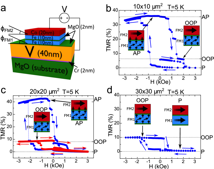
Figure 1 c shows typical OOP TMR cycles measured in two junctions, one of them switching to an AP alignment following an OOP orientation (blue) and the other one only switches to the OOP state (red). Figure 1 d shows an OOP TMR for a junction where the OOP alignment of the FM1 and FM2 electrodes remains stable up to 3 kOe. Note that all junctions showed remanent OOP alignment of the soft Fe(001) electrode once the perpendicular magnetic field is removed (Figure 1). This indicates the relatively small number of interfacial defects present in our junctions, as supported by numerical simulations analyzing the OOP configuration robustness as a function of the density of interfacial defects by studying the inverse OOP to IP transition, which are discussed in Appendix B.2.
The symmetry broken spin reorientation observed in the OOP TMR experiments shown in 1 b-d, has been previously explained in Ref.Martinez2018 by the difference in the dislocation density present at the top and bottom surfaces of the soft Fe(001) layer due to the growth process. This differently affects the top and bottom surface anisotropies, which leads to different intensities at each interface resulting in the magnetization being more easily reoriented into the OOP configuration for one field direction than the other. This asymmetric field behaviour might seem at odds with the Stoner-Rashba model developed in Ref.Barnes2014 . This model suggests that a net Rashba field related to the asymmetric top and bottom interfaces of a ferromagnetic film leads to a pseudo-dipolar contribution to the anisotropy which would mainly favor an in-plane magnetization, and to an uniaxial-like anisotropy favouring the perpendicular magnetization configuration. Correspondingly, the hysteresis curve of a single magnetic (here Fe) layer is expected to be an even function with respect to the external magnetic field. However, we note that the model does not fully account for the complexities discussed below that could lead to the asymmetric hysteresis we observe in our multilayer structures.
The fact that the hysteresis curve is not an even function of the external magnetic field is simply related to the fact that the model is developed for a single ferromagnetic layer, while in our complex heterostructure we do not reverse the Fe/Co interface magnetization. This is not unreasonable considering a large interface anisotropy. A full magnetization reversal including interfacial magnetization would only result in an asymmetric hysteretic response. Secondly, stray field plays a relevant role in our structures and, importantly, the stray field seen by both interfaces is not similar. The bottom interface experiences the stray field of the Fe/Co top bilayer, while the top interface sees the contribution from the bottom Fe layer. In a macrospin model, increasing the stray field would decrease the perpendicular anisotropy. To fully understand the complexities of the asymmetric magnetization response, future studies, such as direct OOP magnetization measurements on the MgO/Fe/MgO structures in the absence of the sensing Fe/Co and V/MgO layers could be performed.
It is worth mentioning a distinct feature of our junctions, having a strongly preferred IP magnetization at room temperature Martinez2018 , with the OOP configuration of the soft 10 nm Fe layer only becoming non-volatile below 80 K. In the temperature range in which this study takes place (0.3 to 7 K), the magnetic field required to induce an OOP transition in the soft layer does not typically exceed 2 kOe. These relatively low values (with respect to continuous 10 nm thick Fe films) could be explained by the combined influence of a few factors. Firstly, the variation of the relation between the IP and OOP anisotropy energies could vary with temperature, possibly favouring the OOP configuration at low temperatures Wang2020 . Secondly, interfacial strain has also demonstrated the potential to induce changes in the perpendicular anisotropy in thin ferromagnetic films Wolloch2021 . Thirdly, the IP saturation in this study was carried out with a field of 3 kOe. This value was considered sufficiently high since the resistance values were stable above 1 kOe, but it could be insufficient to induce a perfect IP alignment at low temperatures. This factor could be more relevant for the smallest junctions where edge magnetic charges would have a relatively higher influence on the measured OOP switching field, qualitatively explaining the dependence of this field with the junctions lateral size, as supported by numerical simulations (see Appendix B.3, figure S9). Finally, as mentioned before, as long as we measure the total resistance of the junction, we can’t exclude that the OOP reorientation might take place preferently in the atomic layers closer to the Fe/MgO interface (where it would be easier to reorient the magnetic moments due to the surface anisotropy). Thus, the surface OOP state (with a thickness of a few nm, close to that of the Fe magnetic exchange length Abo2013 ) might be realized with the aid of interface anisotropy at the Fe/MgO interface and an external OOP magnetic field. This is shown in the sketches of the spin valve configuration in Figure 1 b-d.
II.1 Superconductivity induced change of the out-of-plane anisotropy field
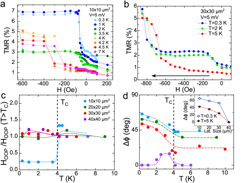
Figure 2 a shows the temperature dependence of OOP TMRs in a junction, in a field range where the field-induced magnetization reorientation of the FM1 layer (measured at 5 mV) takes place. A decrease of the characteristic field (defined as the applied magnetic field providing a complete OOP reorientation of the FM1 layer) just below can be observed upon lowering the temperature, as represented in Figure 2 c. We note that the SC-induced full IP-OOP transitions have been clearly observed in the smallest lateral size junctions. The larger junctions showed a small low field TMR increase below , which could be interpreted either as a partial FM1 layer reorientation or an inhomogeneous OOP alignment (Figure 2 b). For the and larger junctions, the anisotropy field turned out to be nearly independent of temperature (Figure 2 c). Interestingly, our junctions also revealed spontaneous zero field TMR emerging below (corresponding to a partial magnetic reorientation of the soft FM1 layer), which is more pronounced for the smaller samples and diminishes with lateral size, abruptly disappearing for the largest junctions. This is shown in Figure 2 d, where instead of the TMR, the calculated angle between the two FM layer is plotted. It is worth noting that this relative angle calculation is similar to our previous workMartinez2018 ; GonzalezRuano2020 , and assumes a uniform magnetization in the whole FM layer. However, the real scenario could be more complex (see Appendix B).
II.2 Influence of electric field on the out-of-plane reorientation
The presence of the MgO barriers allows us to explore the possible influence of high electric fields on the magnetic-field-induced IP-OOP transitions above and below . High electric field influences the PMA anisotropy by modifying the SOC Rashba field in magnetic tunnel junctions Barnes2014 . Our previous study Martinez2018 revealed that roughly two thirds of the voltage drop in our junctions occurs at the V/MgO/Fe barrier, resulting in a high electric field across this interface. The remaining voltage drops at the Fe/MgO/Fe interface, which is responsible for the change in the resistance providing the measured TMR depending on the relative magnetic configuration of the two FM layers.
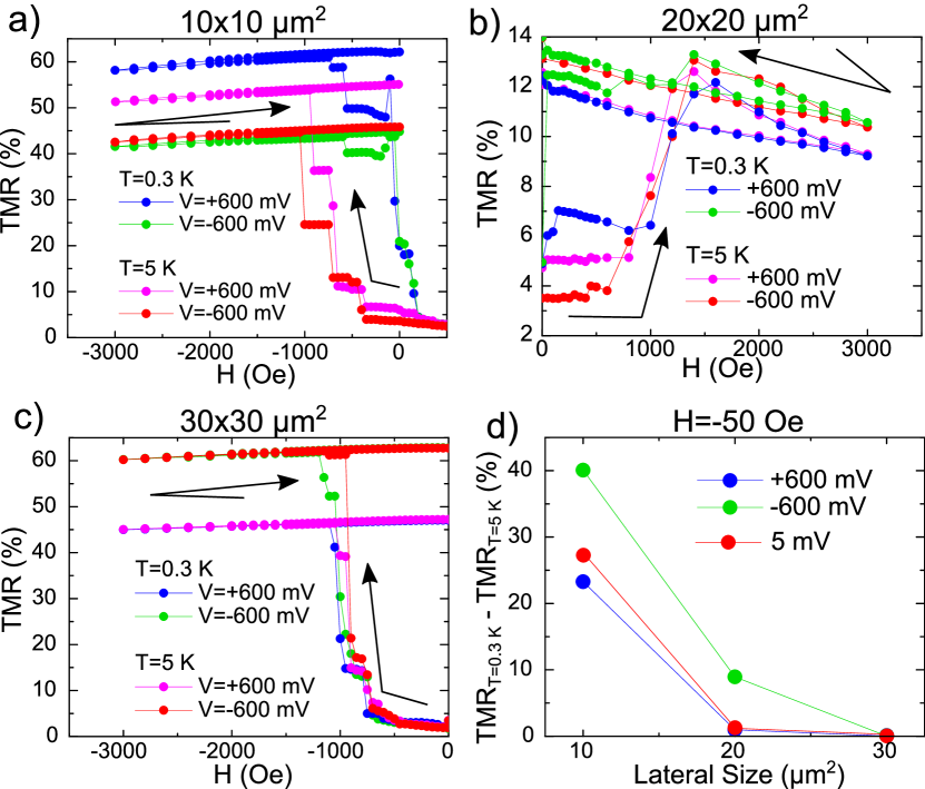
We have therefore investigated the influence of high bias and its polarity on the IP-OOP transition in junctions with different lateral sizes. Figure 3 a-d show that an applied bias of 600 mV (generating an electric field at the V/MgO/Fe interface exceeding V/m) hardly affects above , independently of the junctions size. Moreover, the application of a large electric field has also a negligible effect on the superconductivity-induced IP-OOP transition in the larger than junctions, with a dominant IP magnetization alignment (Figure 3 c). However this changes for the smaller junctions, where IP and OOP anisotropy values are comparable leading to an entirely different behaviour. Strikingly, we observe that for and junctions, the electric field stimulates an IP-OOP transition below at very small values of the applied magnetic field (below 100 Oe).
Figure 3 d compares the influence of an electric bias close to 600 mV with different polarities on the magnetization alignment below (0.3 K) with an applied magnetic field of Oe, within the field range in which we observed a larger influence of the electric field on the IP-OOP transition for the smaller junctions. This field is about an order of magnitude below the first critical field of our Vanadium films, which was estimated to be close to 400 Oe Martinez2020 , therefore minimizing the presence of vortices in the superconducting layer. We believe that the electric field effect asymmetry could be due to the combined influence of the relatively more dominant proximity effects between the SC and FM states at the V/MgO/Fe interface in smaller junctions, and the electric-field-induced variation of the Rashba field influencing the OOP anisotropy for the non-equivalent interfaces MgO/Fe and Fe/MgO in the junctions Barnes2014 .
III Discussion
III.1 Evaluation of magnetostatic coupling between superconducting vortices and ferromagnet
Let us start our discussion by considering different scenarios involving the possible magnetostatic coupling between the superconducting vortices and the ferromagnet Fritzsche2009 . It is tempting to consider the device edges as mainly responsible for the superconductivity-induced spin reorientation, as the edge has a more important contribution for the smallest samples, in which the minimum applied field is enough to fully reorient the magnetization. However, a few experimental facts contradict this scenario. Firstly, the superconductivity-induced additional zero field OOP angle variation is similar for to junctions (see inset in figure 2 d), which would not be the case if the change comes from the device’s edges. The superconductivity induced spin reorientation effect abruptly diminishes for the junction only (Figure 2 d). Secondly, numerical simulations show that the OOP reorientation due to magnetostatic coupling, if relevant, could potentially be triggered by the nucleation of OOP domains in the interior of the samples rather than at the edges; even if we assume the edges as the initial OOP nucleation places, the resulting vortex distribution would affect the whole FM layer (see Appendix B.1). Finally, electric field stimulates the OOP transition for relatively small junctions with competing anisotropies (see Figure 3) which points towards the possible role of the Rashba field.
We have seen from micromagnetic simulations and as an experimental trend that, on average, the normal state increases with the junctions area (Appendix B.3). This is in agreement with the gradual decrease of the partial OOP magnetization reorientation with increasing lateral size seen in the normal state, just above the critical temperature (see Figure 2 d). Within the above picture, a lower field is required to reorient the magnetization perpendicularly in the smallest junctions, and therefore one would expect a weaker magnetostatic coupling to SC vortices.
Numerical simulations of the magnetostatic interaction of the V/MgO/Fe system during an OOP TMR experiment such as the ones shown in figure 1, where a varying OOP magnetic field is applied, is a complex problem which requires self-consistent treatment of the interaction between magnetic charges and stray fields of superconducting vortices Niedzielski2019 . The Appendix B.1 introduces a simplified simulation scheme which evaluates this interaction in the presence of the Meissner effect. These results show that the vortex-mediated magnetostatic interaction might only explain a weak enhancement of in the superconducting state in the largest junctions (Figure 2 c). However, we note that varying the superconducting hysteresis strength or width in the magnetostatic simulations could not explain the strong decrease of below which was experimentally observed in the smaller junctions. Moreover, a dominant magnetostatic coupling would contradict the observed influence of electric field on TMR below for the smallest junctions (Figure 2, 3).
III.2 Microscopic model
To explain the strong decrease in the OOP anisotropy field below for the smallest junctions and the superconductivity-induced zero field magnetic reorientation in all except the largest ones, as well as the influence of the SOC strength through the application of an electric field, we present a microscopic model describing the observed superconductivity-assisted OOP magnetic reorientation. In heterostructures consisting of superconducting and magnetic layers, the superconducting condensate is weakened as Cooper pairs leak into the magnetic regions Eschrig2015 . This leakage is more efficient when the spin-singlets are transformed into equal-spin triplet pairs polarized along the same axis as the magnetization. In our system, the MgO layer boosts the Rashba SOC at the SC/FM interface allowing for a generation of equal-spin triplets that depends on the orientation of the magnetization with respect to the interface Banerjee2018 ; Johnsen2019 .
To show how the efficiency of the triplet leakage affects the critical field for reorienting the magnetization OOP, we calculate the free energy of the system from a tight-binding Bogoliubov–de Gennes (BdG) Hamiltonian (see Appendix C for a complete description of our method). The V/MgO/Fe structure is modelled as a cubic lattice with electron hopping between neighboring sites. We include conventional -wave on-site superconducting pairing potential in the V layer, Rashba SOC in the MgO layer, and an exchange splitting between spins in the Fe layer. Although this model is valid in the ballistic limit, we expect similar results for diffusive materials since spin singlets are partially converted into odd-frequency -wave triplets that are robust to impurity scattering. Moreover, the variation in the singlet population under IP to OOP reorientation of the magnetization have previously been demonstrated both experimentally and by dirty limit calculations Banerjee2018 .
The free energy determined from this model captures the contribution from the superconducting proximity effect, and also includes a normal-state contribution favoring an IP magnetization. In addition, we include a normal-state anisotropy , where ranges from 0º (corresponding to an IP magnetization of the soft ferromagnet) to 90º (OOP magnetization). In total this gives a normal-state anisotropy favoring an IP magnetization, with an additional local minimum for the OOP magnetization direction. Here we only focus on the superconductivity-assisted deepening of these OOP quasi-minima associated with the spin singlet to spin triplet conversion. The increase in below discussed in the previous section is not covered by this theoretical framework, as it does not take into account formation of vortices or the size of the junction. The discussion here is therefore relevant to the smaller junctions where the superconductivity-assisted decrease in dominates.
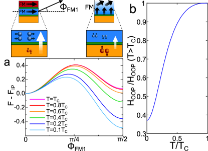
In Fig. 4 a), we demonstrate how the local free energy minimum for an OOP magnetization deepens as the temperature is decreased below . As a simple qualitative model, we calculate the external magnetic field that can be used to force the magnetization into the OOP orientation as , where is the total magnetic moment, is a constant anisotropy favoring the IP orientation that includes the above mentioned parameters for the normal-state IP and OOP anisotropies, and , as well as an energy barrier associated with the reorientation; and and are the calculated free energies in the OOP and IP states of the soft layer respectively. In Fig. 4 b), we show how decreases below as observed for the m2 junction in Fig. 2 c). We have thus demonstrated that the proximity effect enables a strong decrease in that cannot be explained by the coupling of the ferromagnet to superconducting vortices discussed in the previous section. Moreover, since this variation in requires that SOC is present, it also explains the dependence on the electric field observed for the smaller junctions (Fig. 3). The fact that decreases over a longer temperature interval than in the experiments, rather than flattening out for low , is caused by the downscaling of the lattice that is necessary in our theoretical model. In order to scale down the superconducting coherence length so that it remains comparable to the thickness of the superconducting layer, the on-site interaction must be increased, leading to a higher . Since the temperature interval is larger, a smaller fraction of the temperatures exist in the low-temperature limit where the free energy is temperature independent. Keeping in mind that our measurements of show a dependence on the magnitude of the Rashba SOC, we can conclude that the SOC induced change in magnetic anisotropy below shown here must strongly contribute to the suppression in for the m2 junctions.
IV Conclusions
Our experiments point towards the superconductivity induced modification of the perpendicular magnetic anisotropy in the epitaxial Fe(001) films in the V(40 nm)/MgO(2 nm)/Fe(10 nm) system. The behaviour depends on the lateral dimensions of the junctions in the following way: First, for the smallest junctions, the magnetic field necessary for a full OOP magnetization reorientation drops by an order of magnitude in the superconducting state, while for the rest of the junctions it varies only slightly. Second, in all but the largest junctions, an increase in the OOP misalignment angle between the soft Fe(10nm) layer and the hard one is observed when the temperature is decreased below without any applied field. This spontaneous reorientation is similar for to m2 junctions and disappears in the largest ones, suggesting that superconductivity could be affecting the competition between the IP and OOP anisotropies (which is more pronounced for the smaller junctions) rather than being the result of the reorientation taking place at the edges of the samples. The decreasing of transition field in the superconducting state, which could also be stimulated by the application of electric field changing the Rashba SOC, is consistent with the theoretical prediction Johnsen2019 of the absolute minimum of free energy corresponding to the OOP spin direction in SC/SOC/FM hybrids with competing (IP vs OOP) anisotropies just below . The magnetostatic interaction between vortices and magnetic inhomogeneities could explain a weak hardening of the OOP transition in the largest junctions. A detailed theoretical analysis of the mutual interplay between the inhomogeneous magnetization of the soft ferromagnet and the superconductor is, however, beyond the scope of this work. Our results open a route to active manipulation of perpendicular magnetic anisotropy in the expanding field of dissipation-free superconducting electronics involving spin Palermo2020 ; Shafraniuk2019 ; Golod2019 or spin polarized supercurrents Jeon2019 .
V Methods
V.1 Samples growth and characterization
The V(40 nm)/MgO(2 nm)/Fe(10 nm)/MgO(2 nm) /Fe(10 nm)/Co(20 nm) MTJ multilayer stacks have been grown by molecular beam epitaxy (MBE) in a chamber with a base pressure of mbar following the procedure described in Ref. Tiusan2007 . The samples were grown on (001) MgO substrates. A 10 nm thick seed of anti-diffusion MgO underlayer is grown on the substrate to trap the C from it before the deposition of the Fe (or V). The MgO insulating layer is then epitaxially grown by e-beam evaporation up to a thickness of approximately nm and the same process is then executed for the rest of the layers. Each layer is annealed at 450 ºC for 20 min for flattening. After the MBE growth, all the MTJ multilayer stacks are patterned in micrometre-sized square junctions by UV lithography and Ar ion etching, controlled step-by-step in situ by Auger spectroscopy.
V.2 Experimental measurement methods
The measurements are performed inside a JANIS® He3 cryostat (the minimum attainable temperature is 0.3 K). The magnetic field is varied using a 3D vector magnet consisting of one solenoid (Z axis) with T and two Helmholtz coils (X and Y axis) with T. In our system the different magnetic states can be distinguished by looking at the resistance, so the relative orientation between two electrodes can be measured. The magnetoresistance measurements are performed by first setting the magnetic field to the desired value, then applying positive and negative current up to the desired voltage (5 mV unless otherwise stated), and averaging the absolute values of the measured voltage for the positive and negative current, obtaining a mean voltage which is used to calculate the resistance at that point. The temperature is measured and controlled with a LakeShore 340 thermometer.
VI Acknowledgements
We acknowledge Antonio Lara and Miguel Granda for help with simulations and Yuan Lu for help in sample preparations. The work in Madrid was supported by Spanish Ministerio de Ciencia (RTI2018-095303-B-C55) and Consejería de Educación e Investigación de la Comunidad de Madrid (NANOMAGCOST-CM Ref. P2018/NMT-4321) Grants. FGA acknowledges financial support from the Spanish Ministry of Science and Innovation, through the “María de Maeztu” Program for Units of Excellence in (CEX2018-000805-M) and “Acción financiada por la Comunidad de Madrid en el marco del convenio plurianual con la Universidad Autónoma de Madrid en Línea 3: Excelencia para el Profesorado Universitario”. D.C. has been supported by Comunidad de Madrid by contract through Consejería de Ciencia, Universidades e Investigación y Fondo Social Europeo (PEJ-2018-AI/IND-10364). NB was supported by EPSRC through the New Investigator Grant EP/S016430/1. The work in Norway was supported by the Research Council of Norway through its Centres of Excellence funding scheme grant 262633 QuSpin. C.T. acknowledges “EMERSPIN” grant ID PN-IIIP4-ID-PCE-2016-0143, No. UEFISCDI: 22/12.07.2017 and “MODESKY” grant ID PN-III-P4-ID-PCE-2020-0230 No. UEFISCDI: 4/04.01.2021. The work in Nancy was supported by CPER MatDS and the French PIA project “Lorraine Université d’Excellence”, reference ANR-15-IDEX-04-LUE.
Appendix A Correction of the OOP field misalignment
In order to ensure that the magnetic field is perfectly aligned with respect to the FM layers, we calibrate the angle between the V/MgO/Fe plane and the magnetic field created by the vector magnet superconducting coils by performing sub-gap conductance measurements at K for different field directions around each axis. Figure 5 describes the calibration process in detail. The results are robust throughout the studied samples, with a misalignment of 8 degrees with respect to the X-axis superconducting coil, which is accounted for in the OOP experiments. There is no observed in-plane misalignment (Y and Z axis coils).
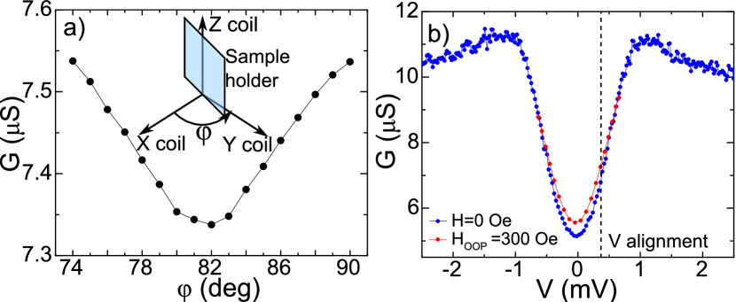
For the highest OOP-AP transition fields measured (about 2000 Oe as shown in Figure 1), the uncertainty of 1 degree in the misalignment calibration for the X coil could result in an IP component of the applied field of 35 Oe, which is about 20 times smaller than the IP coercive field of the hard FM layer GonzalezRuano2020 . Therefore, undesired IP field due to misalignment can be ruled out as an explanation for the observed AP transitions.
Appendix B Numerical simulations
Micromagnetic simulations were carried out using the MuMax3 mumax software in order to estimate (i) the possible influence of Meissner effect on the OOP transition dynamics, (ii) the role of magnetic inhomogeneities caused by defects on the volatility of the OOP magnetic state (characterized by the OOP to IP transition field, ) and (iii) the OOP reorientation dynamics. Additional simulations of the OOP transition were performed varying the lateral size of the simulated samples, in order to contrast the results with the observed enhancement of the OOP transition field with the junctions’ lateral size. The following typical Fe magnetic parameters were implemented on the system: saturation magnetization T ( A/m), exchange stiffness J/m, damping and first order cubic anisotropy J/m3. All simulations were made with K. The simulation cells of the system were set at 128 for the IP components and at 16 for the OOP component. The lateral size of the simulated samples was , with a thickness of 10 nm. The system was additionally surrounded by a vacuum box of an added 100 nm (50 nm on each side) and 3 nm on the top and bottom of the sample, leaving the discretization size of the simulation at nm. Higher discretization in the OOP direction has been chosen on purpose to observe the OOP effects with high accuracy in the simulations. Perpendicular magnetic anisotropy (PMA) was introduced on the top and bottom layers of the Fe as surface anisotropy, with a value of J/m2. Due to computational limitations on the size and detail of the simulations, the results discussed in this section should be taken as qualitative support for the experimental results, rather than quantitative estimations.
B.1 Influence of Meissner effect on the OOP magnetization reorientation
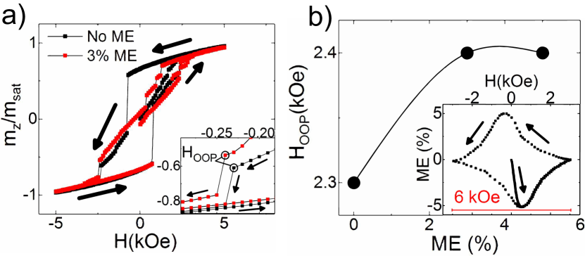
The influence of superconductivity on the OOP transition has been studied by performing micromagnetic simulations with MuMax3 for 10 nm thick, Fe(001) films under the influence of a superconducting vanadium layer. We simulated OOP hysteresis cycles where a correction to the applied field was added based on a typical Meissner effect (ME) hysteresis cycle (obtained from Flukiger2012 , shown in Figure 6b inset), scaled for different values of field contribution from Meissner effect and adapted to the first and second critical fields of vanadium (correspondingly and ). The contribution from superconducting vortices was taken into account by using an in-group developed program that numerically solves the time dependent Ginzburg-Landau equations in order to simulate the behaviour of type II superconductors under magnetic fields Lara2020 . The initial stray fields from an in-plane saturated FM simulation were used to generate a distribution of vortices, and then the fields generated by those vortices were calculated Chang1992 and added into the corrected hysteresis cycle. Our simplified numerical model, although limited, provides qualitative support for the mutual magnetostatic interaction between the FM and SC as the possible origin of the behaviour of the field in the superconducting state. We also note that simulations with a contribution exceeding of Meissner effect resulted in the OOP state being volatile in the hysteresis cycle (i.e. the magnetization returns to an IP configuration before returning to zero field), in contradiction with the experimental observations. Consequently, we have not considered larger contributions of Meissner effect as a possible explanation for the observed behaviour of . We also underline that a complete numerical solution is a great challenge which is outside our current capabilities, as the problem should be solved self-consistently, so the results should be understood in a qualitative way.
Another concern about the OOP reorientation is the possibility of it being a trivial effect produced at the edges of the FM layers. As mentioned in the main text, there is experimental evidence pointing against this possibility. However, a more thorough study has been performed in order to fully discard this scenario. First, we simulated the field-induced OOP reorientation in micron Fe films. As shown in figure 7a, the reorientation seems to be triggered by OOP oriented domains in the interior of the film.

On the other hand, we wanted to see the influence of any possible dominating edge effects on the underlying SC layer. Simulations of micron V films were made using the code described in Appendix B.1 at K, with OOP magnetic fields applied at the edges of the simulated samples. As shown in figure 7b, the stationary state is reached when vortices fill the interior of the film. This would produce high OOP stray fields affecting the interior of the Fe layer, triggering a reorientation in the whole film rather than limiting it to the edges.
B.2 Influence of defects on the OOP-IP magnetization reorientation
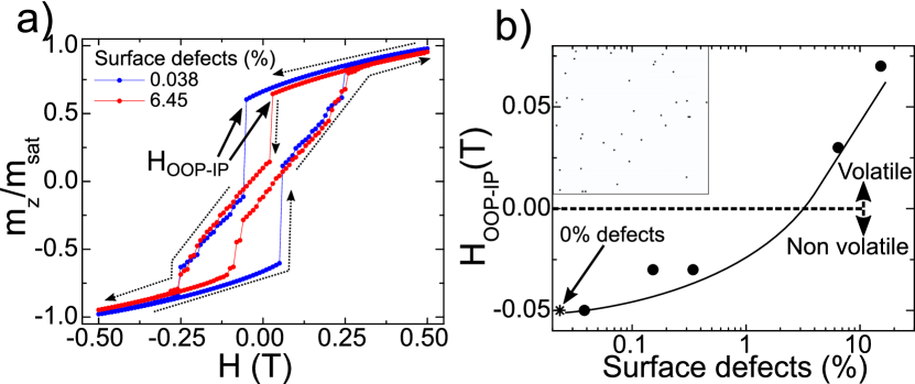
In order to better understand the experimentally observed non-volatility of the OOP state in the junctions, we have simulated numerically the influence of randomly distributed surface magnetization defects within the bottom and top layers of the 10 nm thick Fe layer. The defects are introduced in the simulations as spots of enhanced surface saturation magnetization (). We have found that the introduction of a small number (about ) of magnetic defects per layer does not affect the non-volatity, but only varies the characteristic field of the transition from the OOP state to the IP alignment that takes place after the initial magnetization saturation (Figure 8). Above some critical defect number of about defects per layer the OOP-IP transition becomes volatile. As long as we always observe experimentally non-volatility of this transition in our junctions, we can conclude that there is a relatively small number of magnetic defects present in the epitaxial MTJs under study.
B.3 Dependence of with the junctions lateral size
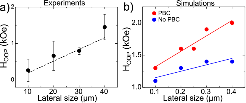
The behaviour of the OOP transition field has been studied as a function of the samples lateral size, in a total of 14 different samples varying from to . We found an increasing trend of with the lateral size, as shown in Figure 9a. Micromagnetic simulations of the same transition have been performed in Fe films with lateral sizes of to (as the real dimensions were computationally prohibitive to simulate) with a qualitative agreement to the experimental results, as shown in Figure 9b. These simulations have been made in the absence of previously discussed phenomena such as defects or Meissner effect.
Appendix C Bogoliubov–de Gennes theoretical model
In order to demonstrate how the superconducting proximity effect can cause a change in the magnetic anisotropy, we consider a tight-binding Bogoliubov–de Gennes model for the V/MgO/Fe heterostructure. This model enables us to calculate the free energy of the system, so that we can study how the energy cost for reorienting the magnetization changes with temperature. We here only focus on the superconductivity-induced decrease in observed for m junctions. Vortex formation and the size of the lattice is not taken into account here, and instead discussed in Section III.1 and in Appendix B.1. For the microscopic model of the V/MgO/Fe heterostructure, we consider the Hamiltonian
| (1) | ||||
The first term describes the nearest-neighbor hopping, where is the hopping integral. The second term describes the chemical potential at each lattice site , and the potential barrier present in the insulating MgO layers. The third term gives rise to an attractive on-site interaction in the superconducting V layer described by the onsite potental . The fourth term introduces a local magnetic exchange field giving rise to ferromagnetism in the Fe layer. The Pauli matrices are contained in the vector . The last term describes the Rashba spin-orbit coupling boosted by the MgO layers, where the spin-orbit field has a magnitude and is directed along the interface normal . The vector connects site and . In the above Hamiltonian, and are the second-quantization electron creation and annihilation operators at site with spin , and is the number operator. The superconducting term is treated by a mean-field approach assuming that , where terms to the second order in the fluctuations are negligible. The superconducting gap is defined as and must be treated self-consistently. The above model is valid in the ballistic limit, but since the effects considered here depend on the formation of -wave odd-frequency triplets that are robust to impurity scattering we would obtain qualitatively the same results in the diffusive limit.
We consider a cubic lattice of size with an interface normal along the axis. We assume periodic boundary conditions in the and directions, and apply the Fourier transform
| (2) |
along these axes. To simplify notation we have defined , , , and . We also use that
| (3) |
The Hamiltonian can be written on the form
| (4) |
where the basis is given by
| (5) | ||||
and where the Hamiltonian matrix consists of blocks
| (6) | ||||
with row and column indices . Above, is the Kronecker product of the Pauli matrices spanning Nambu and spin space, , and
| (7) | ||||
The constant term is given by
| (8) | ||||
By diagonalizing , we obtain eigenvalues and eigenvectors
| (9) | ||||
The diagonalized Hamiltonian can be written as
| (10) |
where the marked sum goes over , , and . Expectation values of the new operators can now be evaluated according to
| (11) | ||||
where is the Fermi-Dirac distribution. The new quasi-particle operators are related to the old operators by
| (12) | ||||
The eigenenergies and eigenvectors obtained in this diagonalization, can be used to calculate physical observables for the system. The superconducting gap is given by
| (13) |
and is treated self-consistently.
We can calculate the critical field for reorienting the magnetization from an IP to an OOP orientation. The Zeeman energy of an external magnetic field is given by
| (14) |
where is the vacuum permeability, is the total magnetic moment, and is the applied field. If we consider a system where the free energy is minimal for an IP magnetization and maximal for an OOP magnetization, and we want to find the external magnetic field needed to reorient the magnetization to the OOP direction, we must require that . We can then calculate the critical field from
| (15) |
To take into account other anisotropy contributions not covered by this model, we let . Above, the free energy is given by
| (16) |
where . The total magnetic moment of the system for an OOP magnetization is given by
| (17) | ||||
when the interface normal is directed along the axis.
Since the lattice must be scaled down in order to make the system computationally manageable, we choose the magnitude of the on-site coupling potential so that the superconducting coherence length is comparable to the thickness of the V layer. The superconducting coherence length is given by , where is the Fermi velocity calculated for the normal-state eigenenergy , and is the zero-temperature superconducting gap.
We determine the superconducting critical temperature by a binomial search, where we decide if a given temperature is above or below . This is decided by finding whether the superconducting gap measured in the middle of the superconducting region increases towards a superconducting solution or decreases towards a normal state solution from the initial guess under iterative recalculations.
In Fig. 4, we have used the parameters , , , , , , , , , , and . This gives a coherence length of lattice sites. All length scales are scaled by the lattice constant , all energy scales are scaled by the hopping parameter , and the magnitude of the spin-orbit coupling is scaled by .
References
- (1) S. N. Piramanayagam, Perpendicular recording media for hard disk drives, Journal of Applied Physics 102, 011301 (2007).
- (2) B. Dieny and M. Chshiev, Perpendicular magnetic anisotropy at transition metal/oxide interfaces and applications, Rev. Mod. Phys. 89, 025008 (2017).
- (3) T. C. Chuang, C. F. Pai, and S. Y. Huang, Cr-induced Perpendicular Magnetic Anisotropy and Field-Free Spin-Orbit-Torque Switching, Phys. Rev. Applied 11, 061005 (2019).
- (4) D. Yi, H. Amari, P. P. Balakrishnan, C. Klewe, A. T. N’Diaye, P. Shafer, N. Browning, and Y. Suzuki, Enhanced Interface-Driven Perpendicular Magnetic Anisotropy by Symmetry Control in Oxide Superlattices, Phys. Rev. Applied 15, 024001 (2021).
- (5) J. Z. Sun, Resistance-area product and size dependence of spin-torque switching efficiency in CoFeB-MgO based magnetic tunnel junctions, Phys. Rev. B 96, 064437 (2017).
- (6) W. A. Challener et al, Heat-assisted magnetic recording by a near-field transducer with efficient optical energy transfer, Nature Photonics 3, 220–224 (2009).
- (7) J-G. Zhu, X. Zhu and Y. Tang, Microwave Assisted Magnetic Recording, IEEE Transactions on Magnetics, 44, 1, 125-131 (2008).
- (8) I. Martínez, C. Tiusan, M. Hehn, M. Chshiev, and F. G. Aliev, Symmetry Broken Spin Reorientation Transition in Epitaxial MgO/Fe/MgO Layers with Competing Anisotropies, Sci. Rep. 8, 9463 (2018).
- (9) C. González-Ruano, L. G. Johnsen, D. Caso, C. Tiusan, M. Hehn, N. Banerjee, J. Linder, and F. G. Aliev, Superconductivity-induced change in magnetic anisotropy in epitaxial ferromagnet-superconductor hybrids with spin-orbit interaction, Phys. Rev. B 102, 020405(R) (2020).
- (10) L. G. Johnsen, N. Banerjee, and J. Linder, Magnetization reorientation due to superconducting transition in heavy metal heterostructures, Phys. Rev. B 99, 134516 (2019).
- (11) N. Banerjee, J. W. A. Robinson and M. G. Blamire, Reversible control of spin-polarized supercurrents in ferromagnetic Josephson junctions, Nature Comm. 5, 4771 (2014).
- (12) B. Baek, W. H. Rippard, S. P. Benz, S. E. Russek and P. D. Dresselhaus, Hybrid superconducting-magnetic memory device using competing order parameters, Nature Comm. 5, 3888 (2014).
- (13) E. C. Gingrich, B. M. Niedzielski, J. A. Glick, Y. Wang, D. L. Miller, R. Loloee, W. P. Pratt Jr. and N. O. Birge, Controllable 0- Josephson Junctions Containing a Ferromagnetic Spin Valve, Nat. Phys. 12, 564 (2016).
- (14) N. Satchell, T. Mitchell, P. M. Shepley, E. Darwin, B. J. Hickey and G. Burnell, Pt and CoB trilayer Josephson junctions with perpendicular magnetic anisotropy, Sci. Rep. 11, 11173 (2021).
- (15) F. S. Bergeret, A. F. Volkov and K. B. Efetov, Long-Range Proximity Effects in Superconductor-Ferromagnet Structures, Phys. Rev. Lett., 86, 4096 (2001).
- (16) R. S. Keizer, S. T. B. Goennenwein, T. M. Klapwijk, G. Miao, G. Xiao and A. A. Gupta, Spin Triplet Supercurrent through the Half-Metallic Ferromagnet CrO2, Nature 439, 825 (2006)..
- (17) Ya. V. Fominov, A. A. Golubov, T. Yu. Karminskaya, M. Yu. Kupriyanov, R. G. Deminov and L. R. Tagirov, Superconducting Triplet Spin Valve, JETP Letters, 91, 308 (2010).
- (18) P.V. Leksin, N. N. Garif’yanov, I. A. Garifullin, Ya.V. Fominov, J. Schumann, Y. Krupskaya, V. Kataev, O. G. Schmidt and B. Büchner, Evidence for Triplet Superconductivity in a Superconductor-Ferromagnet Spin Valve, Phys. Rev. Lett., 109, 057005 (2012).
- (19) F. S. Bergeret and I. V. Tokatly, Singlet-Triplet Conversion and the Long-Range Proximity Effect in Superconductor-Ferromagnet Structures with Generic Spin Dependent Fields, Phys. Rev. Lett., 110, 117003 (2013).
- (20) N. Banerjee, J. A. Ouassou, Y. Zhu, N. A. Stelmashenko, J. Linder, M. G. Blamire, Controlling the superconducting transition by spin-orbit coupling, Phys. Rev. B 97, 184521 (2018).
- (21) N. Satchell, N. O. Birge, Supercurrent in ferromagnetic Josephson junctions with heavy metal interlayers, Phys. Rev. B 97, 214509 (2018).
- (22) I. Martínez, P. Högl, C. González-Ruano, J. P. Cascales, C. Tiusan, Y.Lu, M. Hehn, A. Matos-Abiague, J. Fabian, I. Žutić, and F. G. Aliev, Interfacial Spin-Orbit Coupling: A Platform for Superconducting Spintronics, Phys. Rev. Applied 13, 014030 (2020).
- (23) S. V. Dubonos, A. K. Geim, K. S. Novoselov, and I. V. Grigorieva, Spontaneous magnetization changes and nonlocal effects in mesoscopic ferromagnet-superconductor structures, Phys. Rev. B 65, 220513(R) (2002).
- (24) M. V. Milošević and F. M. Peeters, Interaction between a superconducting vortex and an out-of-plane magnetized ferromagnetic disk: Influence of the magnet geometry, Phys. Rev. B 68, 094510 (2003).
- (25) H. X. Yang, M. Chshiev, B. Dieny, First-principles investigation of the very large perpendicular magnetic anisotropy at Fe—MgO and Co—MgO interfaces. Phys. Rev. B 84, 054401 (2011).
- (26) L. E. Nistor, B. Rodmacq, S. Auffret, A. Schuhl, M. Chshiev and B. Dieny, Oscillatory interlayer exchange coupling in MgO tunnel junctions with perpendicular magnetic anisotropy, Phys. Rev. B 81, 220407(R) (2010).
- (27) S. E. Barnes, J. Ieda and S. Maekawa, Rashba Spin-Orbit Anisotropy and the Electric Field Control of Magnetism, Scientific Reports 4, 4105 (2014).
- (28) W. Wang, J. Zhang, X. Shen, X. Guan, Y. Yao, J. Li, C. Gu, J. Sun, Y. Zhu, J. Tao and R. Yu, Out-of-plane magnetic anisotropy enhancement in La1-xSrxCoO3-δ/La2/3Sr1/3MnO3/La1-xSrxCoO3-δ thin films, Phys. Rev. B 101, 024406 (2020).
- (29) M. Wolloch and D. Suess, Strain-induced control of magnetocrystalline anisotropy energy in FeCo thin films, Journal of Magnetism and Magnetic Materials 522, 167542 (2021).
- (30) G. S. Abo, Y-K. Hong, J. Park, J. Lee, W. Lee and B-C. Choi, Definition of Magnetic Exchange Length, IEEE Transactions on magnetics 49, 8 (2013).
- (31) J. Fritzsche, R. B. G. Kramer, and V. V. Moshchalkov, Visualization of the vortex-mediated pinning of ferromagnetic domains in superconductor-ferromagnet hybrids, Phys. Rev. B 79, 132501 (2009).
- (32) B. Niedzielski and J. Berakdar, Controlled Vortex Formation at Nanostructured Superconductor/Ferromagnetic Junctions, Phys. Status Solidi B 257, 7 (2019).
- (33) M. Eschrig, Spin-polarized supercurrents for spintronics: a review of current progress, Rep. Prog. Phys. 78 104501 (2015).
- (34) X. Palermo, N. Reyren, S. Mesoraca, A. V. Samokhvalov, S. Collin, F. Godel, A. Sander, K. Bouzehouane, J. Santamaria, V. Cros, A. I. Buzdin, and J. E. Villegas, Tailored Flux Pinning in Superconductor-Ferromagnet Multilayers with Engineered Magnetic Domain Morphology From Stripes to Skyrmions, Phys. Rev. Applied 13, 014043 (2020).
- (35) S.E. Shafraniuk, I.P. Nevirkovets, and O.A. Mukhanov, Modeling Computer Memory Based on Ferromagnetic/Superconductor Multilayers, Phys. Rev. Applied 11, 064018 (2019).
- (36) T. Golod, O.M. Kapran, and V.M. Krasnov, Planar Superconductor-Ferromagnet-Superconductor Josephson Junctions as Scanning-Probe Sensors, Phys. Rev. Applied 11, 014062 (2019).
- (37) K-R. Jeon, C. Ciccarelli, H. Kurebayashi, L. F. Cohen, X. Montiel, M. Eschrig, T. Wagner, S. Komori, A. Srivastava, J. W. A. Robinson, and M. G. Blamire, Effect of Meissner Screening and Trapped Magnetic Flux on Magnetization Dynamics in Thick Nb/Ni80Fe20/Nb Trilayers, Phys. Rev. Applied 11, 014061 (2019).
- (38) C. Tiusan, M. Hehn, F. Montaigne, F. Greullet, S. Andrieu and A. Schuhl, Spin tunneling phenomena in single crystal magnetic tunnel junction systems, J. Phys.: Condens. Matter 19, 165201, (2007).
- (39) A. Vansteenkiste, J. Leliaert, M. Dvornik, M. Helsen, F. Garcia-Sanchez and B. Van Waeyenberge, The design and verification of MuMax3, AIP Advances 4, 107133 (2014).
- (40) R. Flükiger, Overview of Superconductivity and Challenges in Applications, Reviews of Accelerator Science and Technology 5, 1-23, (2012).
- (41) A. Lara, C. González-Ruano and Farkhad G. Aliev, Time-Dependent Ginzburg-Landau Simulations of Superconducting Vortices in Three Dimensions, Low Temperature Physics/Fizika Nizkikh Temperatur, 46, 4, 386-394 (2020).
- (42) A. M. Chang, H. D. Hallen, L. Harriott, H. F. Hess, H. L. Kao, J. Kwo, R. E. Miller, R. Wolfe and J. van der Ziel, Scanning Hall probe microscopy, Appl. Phys. Lett. 61, 1974 (1992).