Vertical Bicycle Model of Vehicle with Dry Friction
G.M. Rozenblat1
Moscow Automobile and Road Construction State Technical University
e-mail: gr51@mail.ru
V.B. Yashin 2
Moscow Technical University of Communications and Informatics
e-mail: hekkoki@gmail.com
Abstract. The motion of a vertically positioned bicycle is considered when a horizontal control force, which maybe both internal and external in relation to the bicycle, is applied to its pedal. Tangential forces of dryfriction obeying the Euler – Coulomb law act at points of contact of the wheels with the horizontal supportplane. The constraint at the points of contact of the wheels with the support is assumed to be unilateral.The problem of determining the acceleration of the centre of mass of the bicycle and the realized motionsof its wheels (with or without slip, and with or without detachment) with dierent values of the design parameters and control force is solved. This approach is usefull for control of vehicle and optimization of its dynamical parameters. Cases of non-uniqueness of motion the Painleve paradox are found.
Introduction
The movements of bodies by means of change in the positions of internal (relative to the body) masses occur on exposure to external forces, which generally are friction forces (resistance forces, hydrodynamic forces, gravitational forces). The creation of such effective (optimum) external forces is due to the corresponding synthesis of internal forces on exposure to which admissible movements of internal masses are realized (Ref. p. 344). Such problems have been examined (see, for example, Refs ) for the purposes of creating robotic devices. In some problems, internal forces are used to create a variable shape of a body moving in liquid, [8–10]. In space dynamics, internal forces can be used for controlled change in the external gravitational force, which can move such a body away from the Earth by as great a distance as desired (the ’graviflight’ effect, see Ref. Essay 9).
The movement of a bicycle (and any self-propelled vehicle) also belongs to this class of problems of the movement of bodies. Here, the internal (control) force is the force applied to the pedal by the cyclist’s foot. External forces, which realize the motion of the bicycle, are the gravitational forces and the forces of reactions at the points of contact of the wheels with the road.
1 The formulation and solution of the two simplest problems of bicycle motion
Figure 1 depicts a bicycle moving in the vertical position relative to a stationary right-handed coordinate system Oxyz which is selected in the following way. The axis coincides with the horizontal support line along which the bicycle is moving and is oriented to the right, and the axis is directed down the vertical. Thus, the vertical plane coincides with the plane of the bicycle and with the plane The z axis is perpendicular to the plane and forms with the and axes a right-handed coordinate system. Thus, the axis is perpendicular to the plane of the figure and is directed away from the reader. With this choice of coordinate system, all the turns, angular velocities, and angular accelerations of the bodies in the figure that occur in a clockwise direction are considered to be positive. It is clear that these turns, angular velocities, and angular accelerations, when viewed from the positive direction of the axis, are oriented anticlockwise in this case and are positive, as assumed in theoretical mechanics for three-dimensional space. Similar properties are also achieved for the moments of forces: if a force turns the body clockwise about a selected point, from the point of view of the reader looking at the figure, then the moment of this force relative to the examined point is positive, and in the opposite case it is negative. Below, unless stipulated otherwise, we will assume that the introduced kinematic parameters are positive in the sense indicated above. The true signs of these quantities are obtained as a result of solving the problem.
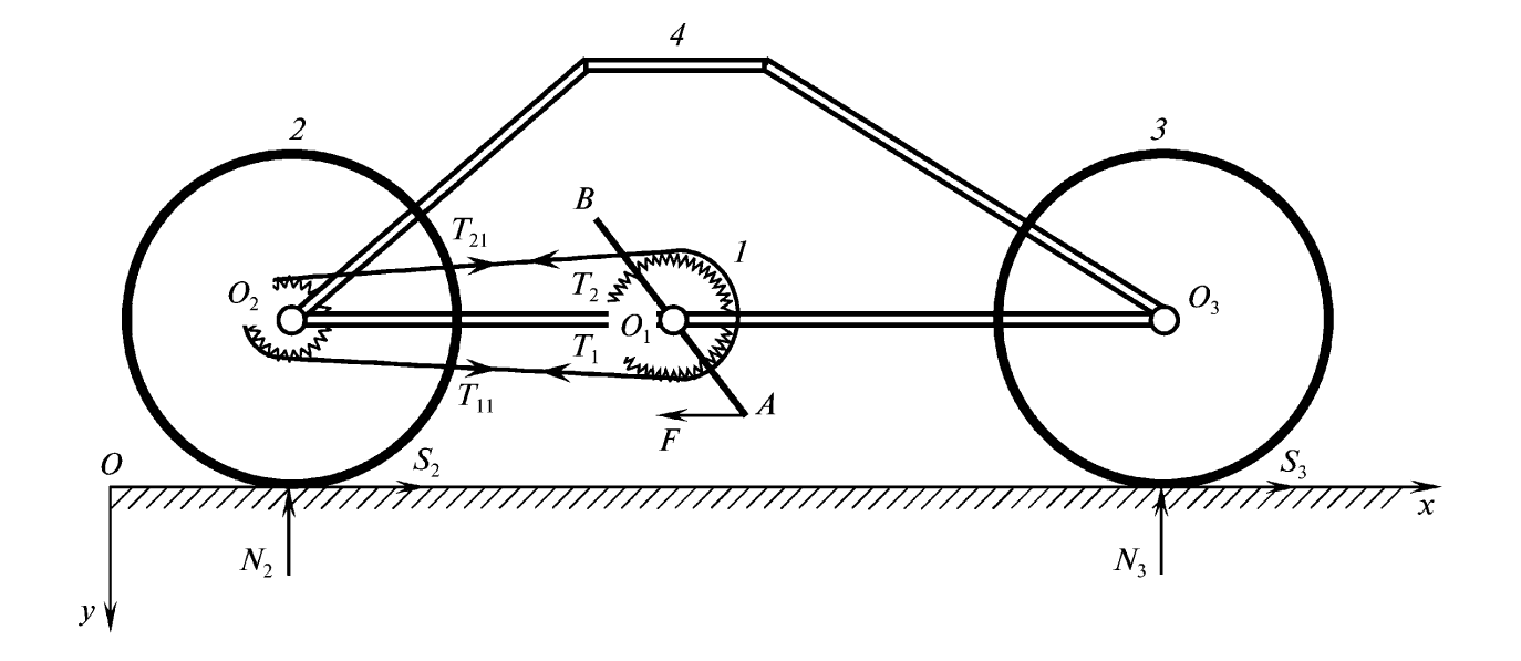
A bicycle consists of four bodies: 1 – the sprocket with the pedals; 2 and 3 – the two wheels; 4 – the frame to which the bodies 1,2, and 3 are hinged at points and as shown in Fig. It is assumed that the cyclist moving the bicyle along the horizontal axis by applying to the lower pedal an internal horizontal force oriented against the direction of the axis is also rigidly connected to the frame.
We will introduce the following notation: and are the velocity and the acceleration of the centre of mass of the bicycle along the axis, and are the angular velocities and accelerations of the sprocket the rear wheel and the front wheel 3) is the moment of inertia of the body relative to the inherent centre of mass, is the total mass of the bicycle (including the cyclist when seated on the bicycle is the radius of the sprocket with the pedal, is the radius of the sprocket on the rear wheel, is the gear ratio, is the external radius of the wheels 2 and and are the normal reaction and the tangential reaction at the point of contact of the wheel with the road, is the distance from the point of contact of the wheel to the centre of mass of the bicycle along the horizontal, is the half-distance between the points of attachment of the wheels along the horizontal, is the elevation of the centre of mass of the bicycle (together with the cyclist when seated on the bicycle) above the road, is the force applied by the cyclist to the lower pedal of the sprocket 1 and directed along the horizontal against the positive direction of the axis, is the corresponding arm (i.e., the distance from the pedal to the horizontal ), and is the difference in the moduli of the forces of tension of the chain that are applied to the sprocket 1.
Let us examine the following problems (below it is assumed that there is no slip of the wheels).
Problem 1. In the standard situation, when the force applied by the cyclist is internal relative to the indicated system of four bodies, determine the acceleration of the centre of mass of the bicycle (together with the cyclist) along the axis.
Problem 2. In the non-standard situation, when the force is external relative to the indicated system of four bodies (the cyclist has dismounted from the bicycle and is applying force to the lower pedal against the direction of the axis or is employing the services of an external aid), determine the acceleration of the bicycle along the axis.
In particular, in both cases, if before the application of force the bicycle is at rest, then the side to which it will begin to move - in the direction of force or in the opposite direction to this force - must be indicated.
1.1 Solutions of the problems
We will use the theorem of change in kinetic energy (Ref. 12, p. 69). Assuming that the wheels are rolling without slip, and the drive chain of the bicycle is unstretchable, we will obtain the following kinematic relations:
| (1.1) |
The kinetic energy of the bicycle, with the use of relations (1.1), is calculated by means of the formula
| (1.2) |
To calculate the power of all internal and external forces, we will consider that in Problem 1 a non-zero contribution is made by the power of the internal force , which creates the moment applied to the body 1 rotating at angular velocity . In Problem 2, a non-zero contribution is made by the external force applied to the lower pedal of the bicycle having the following projection of absolute velocity onto the axis:
| (1.3) |
The remaining (both internal and external) forces make a zero contribution owing to the absence of slip of the wheels, the absence of stretchability of the drive chain, and the ideal hinges at points . Thus, the power is determined by the expression
We will describe in greater detail how the formula for power is obtained. We will transfer to point the force applied to the pedal . As a result we obtain the force applied at point and a pair of forces with moment . This system of forces is applied to the body 1 rotating about point and moving forwards together with this point. According to Newton’s third law, on the body 4 (on whose side this system of forces is applied) at point is acted upon by a force and a pair of forces with moment . The body 4 does not rotate. and therefore the power of the latter moment is zero, and the two oppositely directed and applied forces at point together provide zero power. Thus, a non-zero contribution is made only by the power of the indicated pair of forces applied to the body 1 rotating at angular velocity , and we arrive at the expression given above for power . Then, using the theorem of change in kinetic energy, we will obtain
| (1.4) |
| (1.5) |
The parameters and were defined, respectively, by the second equality of system (1.2) and the second equality of system (1.3). From this it follows that in problem 1 the bicycle moves along the axis, against the force , and in problem 2 with (with ) the bicycle moves against (along) the axis, in the direction (against the direction) of the force . For normal designs of bicycles, , Then and the bicycle moves in the direction of the external force .
Remark 1. Similar problems for a bicycle (three-wheel) on a qualitative level were proposed at the All-Union Physics Olympiads in the (see Ref. 13, problems 98 and 106). As can be seen, the strict and complete solution is fairly complex (for the student), and the sound solution of Problems 1 and 2 requires physical intuition.
Remark 2. The excellent book by Arnold 14 contains the essay ’Which force drives the bicycle forwards?’. The author applies a backward force to the lower pedal of the bicycle and shows that the bicycle will move forwards. As can be seen, this outcome contradicts the answer to Problem 2 (with adherence to the inequality , as occurs for real bicycle models). The present author learnt of this discrepancy from V.F. Zhuravlev, and, in part, it prompted the author to write the present paper. It may be obvious (see Fig. 1) that the force creating a clockwise moment applied to the sprocket will rotate the latter likewise in a clockwise direction. The sprocket, in turn, with the help of the chain, will force the wheels of the bicycle (in the absence of slippage) to rotate clockwise, which will lead to movement of the bicycle from left to right, i.e., against the force . However, the moment from the forces of tension of the chain, which is also applied to the sprocket with the pedals, must also be taken into account. This moment may be directed anticlockwise and may be sufficiently great to exceed the moment from the force and force the sprocket to rotate anticlockwise. This may lead to movement of the bicycle from right to left, in the direction of the force . Such a situation comes about when the force is external and the parameters of the bicycle satisfy the condition . If, however, the force is internal, then, as shown above, the given situation can never be realized, i.e., the bicycle will move against the direction of the force .
2 The general problem of controlling the motion of a bicycle in the vertical plane using an internal or external force applied to the lower pedal statement of the problem of determining the accelerations
The force directed along the horizontal and against the axis (Fig. 1) is applied to the pedal (i.e., to the body 1) either as in Problem 1 or as in Problem 2. Thus, this force is either internal or external. The bicycle at the initial instant is at rest. It is required to determine the dynamics of its motion at fairly short times on the assumption that the wheels are in contact in a unilateral way with a rough support plane with a Coulomb friction coefficient .
Remark 1. The use of an internal force in the way indicated above (as in Problem 1) is equivalent to applying a corresponding control moment to the wheel which is characteristic of motorcycles, where such a moment is created by the motor.
Remark 2. It can be assumed that the bicycle has completed uniform uncontrolled motion without wheel slip, and that the cyclist has then decided to begin controlled motion in the way indicated above.
Remark 3. Unilateral contact of the wheels with the support plane makes it possible to consider the well-known trick of motion with one of the wheels separated from the support. The situation where both wheels are separated is not ruled out either, but these are different problems.
2.1 The principal equations of the kinematics and dynamics of motions of the bicycle without separation of the wheels
Let the force be internal (as in Problem 1). We will write three equations of the dynamics of planar motion of the bicycle, taking into account that the centre of mass does not move along the vertical:
| (2.1) |
| (2.2) |
Equations (2.1) are the equations of motion of the centre of mass of the bicycle along the horizontal and vertical, while Eq. (2.2) is the equation of change in the angular momentum of the bicycle relative to its intrinsic centre of mass.
We will describe in greater detail how Eq. (2.2) is obtained. Suppose is the velocity of the centre of mass of the body It is clear that where is the velocity of the centre of mass of the bicycle, which is directed along the axis. Let be a system of König coordinates ( is the centre of mass of the bicycle), and let and be the mass and vertical coordinate of the centre of mass of the body in the system. Then, for time derivatives from the kinetic moments of the bodies relative to their general centre of mass , we will obtain
Summing up these expressions and using the equality
we will obtain the left-hand part of Eq. (2.2). The right-hand part is obtained in the standard way. We will write equations for the changes in the kinetic moments of the bodies and 3 separately in relation to their intrinsic centres of mass, taking into account that forces of tension of the chain and are applied to the body 1, and the same forces but with opposite signs are applied to the body We will obtain
| (2.3) |
Then, we will write the kinematic equation that follows from the condition of the absence of stretchability of the drive chain between the sprocket 1 and the sprocket of the wheel 2 :
| (2.4) |
The use of Eqs (2.3) makes it possible to write Eq. (2.2) in the form
| (2.5) |
Excluding and from the obtained equations, we will have the following system of five equations:
| (2.6) |
where the following notation is introduced:
| (2.7) |
and parameter is defined by the last equality in system (1.3). If the force is external (as in Problem 2), it is not difficult to show that, instead of system (2.6), we obtain a system differing from system (2.6) in the presence of the term in the first equation and the term in the final equation.
In system and are unknown quantities to be determined (in both problems, both for an internal and for an external force ).
Thus, for correct and unambiguous solution of system (2.6) or the similar system in the case of an external force, it is necessary to have two more equations, which are obtained additionally from physical considerations following from the proposed possible motion of the bicycle. We will give the additional equations for different cases of possible motions of this kind: neither of the wheels 2 and 3 slips:
the wheel 2 (wheel 3) slips, while the wheel 3 (wheel 2) does not slip:
both the wheels 2 and 3 slip:
Before setting out the solutions of the corresponding equations of the dynamics in the four given cases, we will examine the possibility of static equilibrium of the bicycle with the indicated application of an internal or external force to the pedal and the presence only of frictional forces of rest at the contact points of the wheels. We will show that for a bicycle (more accurately, for the combination of rigid bodies making up the bicycle, with or without a cyclist, depending on the examined problem) such equilibrium is impossible with any non-zero force if there are no moments of rolling friction on its wheels. In fact, if the force is internal, the equations of static equilibrium have the form
| (2.8) |
from which it follows that and , i.e., equilibrium is possible only at zero force . If the force is external, then the term is added to the left-hand part of the first equation of system and the term to the left-hand part of the third equation. From these equations it follows that and The last two equations are possible only if For a real bicycle, , and the refore , i.e., the pedal rests on the support plane. Thus, static equilibrium is again impossible. Note that a similar conclusion is also correct when force is inclined to the horizontal.
Remark. In their problem book (Ref. 15, p. 81), Gnädig et al. give an erroneous solution for the case where the force is external. This error stems from the priori assumption that the system of bodies making up the bicycle is in equilibrium. On this basis, three equations of equilibrium are examined for the system as a whole as an absolutely rigid body. However, these equations are the consequence of the indicated assumption and cannot be a criterion for retention of static equilibrium of the examined system of bodies. As can be seen, a more detailed analysis taking into account the specific nature of the examined system of rigid bodies leads to the impossibility of static equilibrium of the bicycle at any force , either internal or external.
3 Formulating the results for the case of an internal force
In this section, we will formulate the results that are obtained by applying to the pedal of the bicycle an internal force (as in Problem 1 from Section 1) for the four cases indicated above. Everywhere below, unless stipulated otherwise, it is assumed that
Furthermore, to simplify the formulae, it has been assumed that (i.e., the total mass of the bicycle with the cyclist is selected as the unit for measurement of mass). We will introduce the following (already dimensionless) notation:
| (3.1) |
Assertion 1. When the bicycle moves without slip of either wheel, the following conditions are fulfilled:
The acceleration of the centre of mass of the bicycle in this case is given by formula (1.4).
Assertion 2. To realize motion of the bicycle with slip of the front wheel 3 only (wheel 3 slips forwards), the following conditions are fulfilled (in each of the examined cases, the corresponding acceleration of the centre of mass of the bicycle is given in parentheses):
if then
if then
if , then
if , then this motion is impossible.
Assertion 3. When the bicycle moves with slip of the rear wheel 2 only (wheel 2 slips backwards), the following conditions are fulfilled:
if tnen this motion is impossible.
Assertion 4. When the bicycle moves with slip of both wheels (the wheel 2 in this case slips backwards, and the wheel 3 slips forwards), the following conditions are fulfilled:
if then
if then
if then this motion is impossible.
Substantiation of these assertions is given in Section 4.
The combination of the assertions 1 to 4 leads to the following assertion.
Assertion 5. If and , then motion occurs either without slip of either wheel or with slip of the front wheel (ambiguity). In all remaining cases, motion is unambiguous in accordance with the results of the assertions 1 to or loss of the unilateral constraint occurs for the front wheel.
Remark 1. From Assertion 5 it follows that, when certain conditions are fulfilled, the motion is ambiguous (the Painlevé paradox). The realized motion of the bicycle depends on the prehistory of its movement. Such issues are discussed in detail in other papers by the present author. 16,17
Remark 2. The loss (weakening) of the unilateral constraint for the front wheel of the bicycle occurs at a fairly high force . In this case, the normal reaction on the front wheel becomes negative. Further motions of the bicycle with possible separations of the front wheel should be considered in a separate problem.
Remark 3. If , then only cases of the Assertions 1 and 2 are realized, from which, in part, there follow the results of solving the Problem 1 from Section 1 for the motion of the bicycle without wheel slip. However, the ambiguity (i.e., the additional possibility of motion with slip of the front wheel with certain values of the force is retained. This was pointed out to the author by F.L. Chernous’ko.
Remark 4. It is surprising that motions of the bicycle with slip of the front (driven) wheel are possible. In fact no moments are applied to this wheel. However, it must be borne in mind that at the centre of the front wheel there acts a horiz ontal force of reaction from the bicycle frame. It is this force that may in certain situations cause slip of the front wheel. A problem of this type for one wheel with a horizontal force applied at its centre is given in Meshcherskii’s problem book (Ref. 18, problem 35.4). The complete solution of this problem is available. 19
4 Substantiation of the results of Section 3
4.1 Proof of Assertion 1
The solution of system of equations (2.6) with the corresponding additional equations and notation (3.1) leads to the formulae
| (4.1) |
For the correct realization of the examined motion, it is necessary to ensure that the inequalities of the unilateral constraints , are observed, and also the Coulomb inequalities and for the frictional forces of rest and . The use of these inequalities together with relations (4.1) and notation (3.1) leads to the results of the Assertion
4.2 Proof of Assertion 2
The solution of system of equations (2.6) with the corresponding additional equations and allowance for notation (3.1) leads to the formulae
| (4.2) |
Then, it is not difficult to estimate that
| (4.3) |
from which it follows that the value cannot be real ized, as in this case, under the conditions and we obviously obtain which leads to a contradiction when .
Thus, only is possible, i.e., the front wheel can only slip forwards over the course of motion along the axis. Then, we will obtain
| (4.4) |
Using the inequality and the Coulomb inequality for and , from formulae (4.2) to (4.4) we will obtain
| (4.5) |
and are defined by formulae (4.4). Then, from relations (4.4) and (4.5) follow the inequalities
| (4.6) |
Hence, when we obtain
| (4.7) |
The magnitude of is given by the second equation in the third line of formulae (3.1). If , then in relations (4.7) all the signs of the inequalities must be changed to the opposite signs. To solve the obtained inequalities (4.7), we will introduce, using notation (3.1), the following functions of parameter :
| (4.8) |
In accordance with inequalities (4.7), these functions limit the upper and lower values of EST, depending on the value of the parameter , and when they acquire the same value
An analysis of inequalities (4.7) with the use of functions (4.8) and their elementary properties leads to the results of the Assertion 2.
4.3 Proof of Assertion 3
The solution of system of equations (2.6) with the corresponding additional equations and notation (3.1) leads to the formula
from which we will obtain the equality
| (4.9) |
From this, with , we arrive at a contradiction, as then, with and , obviously we will have Thus, we have and (the rear wheel 2 may slide only backwards, against the direction of the axis), and from the relation (4.9) we will obtain the inequality
| (4.10) |
Furthermore, the Coulomb inequality for the force leads to the relation
| (4.11) |
Then, simple calculations lead to the following formulae for normal reactions:
| (4.12) |
For the realization of the examined motion, it is still necessary to add the inequalities and which, with account taken of formulae (4.12), leads to the double inequality
| (4.13) |
Thus, for the realization of the examined motion, it is necessary to observe the inequalities and (4.13) with account taken of the formulae (4.12). As a result of simple calculations, we obtain the inequalities of the assertion
4.4 Proof of Assertion 4
The solution of the system of equations (2.6) with the corresponding additional equations and notation (3.1) leads to the formulae
| (4.14) |
Simple analysis of formulae with account taken of the inequalities and leads to the conclusion that only the set with which the inequalities and should be observed, is consistent. Thus, here the rear wheel slides backwards, and the front wheel forwards. Then, from the relations (4.14) we will obtain the inequalities
| (4.15) |
Simple calculations lead to the following expressions for normal reactions:
| (4.16) |
and inequalities (4.15) acquire the form
| (4.17) |
The parameter is defined by the final equality in the fourth line of formulae (3.1). Considering the two cases and from inequalities (4.16) and (4.17) we will obtain the results of Assertion
References
- [1] Appel P. Traté de Mécanique rationelle. Tom 2. Paris: Gauthier-Villars; 1941.
- [2] Okhotsimskii Dye, Martynenko YuG. New problems of the dynamics and control of the motion of mobile wheeled robots. Uspekhi Mekh .
- [3] Martynenko YuG, Formal’skii AM. The theory of control of a monocycle. J Appl Math Mech .
- [4] Chernous’ko FL. Analysis and optimization of the motion of a body controlled by means of a movable internal mass. J Appl Math Mech .
- [5] Akulenko LD, Bolotnik NN, Kumakshev SA, Nesterov SV. Control of motion of an inhomogeneous cylinder with internal movable masses along a horizontal plane. J Appl Math Mech
- [6] Bolotnik NN, Figurina TYu. Optimal control of the rectilinear motion of a rigid body on a rough plane by means of the motion of two internal masses. J Appl Math Mech
- [7] Bolotnik NN, Figurina TYu, Chernous’ko FL. Optimal control of the rectilinear motion of a two-body system in a resistive medium. J Appl Math Mech .
- [8] Lavrent’ev MA, Lavrent’ev MM. A principle of the generation of propulsion force. Prikl Mekh Tekh Fiz
- [9] Kozlov VV, Ramodanov SM. The motion of a variable body in an ideal fluid. J Appl Math Mech .
- [10] Chernous’ko FL. Motion of a body in a fluid due to attached-link oscillations. Dokl Phys .
- [11] Beletsk VV. Essays on the Motion of Celestial Bodies. Basel: Birkhāuser; 2001.
- [12] Zhuravlev VF. The Principles of Theoretical Mechanics. 3rd Edn. Moscow: Fizmatlit; 2008. p. 304.
- [13] Slobodetskii ISh, Orlov VA. All-Union Physics Olympiads: Textbook for Classes 8–10 Middle-School Students. Moscow: Prosveshcheniye; 1982. p.
- [14] Arnold VI. Mathematical Understanding of Nature: Essays on Amazing Physical Phenomena and their Understanding by Mathematicians. Providence, RI: Amer Math Soc; 2014.
- [15] Gnädig P. Honyek G, Riley K. 200 Puzzling Physics Problems with Hints and Solutions. Cambridge: University Press; 2002.
- [16] Rozenblat GM. The motion of a plane rigid body on a rough line. Nelin Din
- [17] Rozenblat GM. Formulating problems in the dynamics of forced motion of a rigid body and the Painlevé paradox. Vestn Udmurt Univ Mat Mekh Komp’yut Nauki 2009:(2)
- [18] Meshcherskii IV. Problems of Theoretical Mechanics. Textbook. St Petersburg: Lan’: p. 448.
- [19] Kozlova ZP, Panshina AV, Rozenblat GM. In: Rozenblat GM, editor. Theoretical Mechanics in Solutions of Problems from I. V. Meshcherskii’s Collection: The Dynamics of a Material System. Textbook. Moscow: zd LKI; 2007. p. 432.
- [20] Rozenblat G. M., The controlled motion of a bicycle. Journal of Applied Mathematics and Mechanics, 2016, vol. 80, no 2, pp. 133–140.