Ab initio calculation of the detailed balance limit to the photovoltaic efficiency of single p-n junction kesterite solar cells
Abstract
The thermodynamic limit of photovoltaic efficiency for a single-junction solar cell can be readily predicted using the bandgap of the active light absorbing material. Such an approach overlooks the energy loss due to non-radiative electron-hole processes. We propose a practical ab initio procedure to determine the maximum efficiency of a thin-film solar cell that takes into account both radiative and non-radiative recombination. The required input includes the frequency-dependent optical absorption coefficient, as well as the capture cross-sections and equilibrium populations of point defects. For kesterite-structured \ceCu2ZnSnS4, the radiative limit is reached for a film thickness of around , where the efficiency gain due to light absorption is counterbalanced by losses due to the increase in recombination current.
The efficiency of solar cells is determined by the thermodynamics of light and matter. For single p-n junction solar cells, the first theoretical investigation on the efficiency was given by Shockley and Queisser (SQ),Shockley and Queisser (1961) where bandgap is the sole parameter that determines the energy loss mechanisms including light absorption, hot carrier cooling, and radiative recombination. In this model, the absorbance and non-radiative recombination rate are generally assumed to be 1 and 0, respectively. For this reason, bandgap is often the main descriptor used in computational materials discovery for solar energy applications.Castelli et al. (2012)
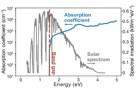
The wavelength-dependent optical absorbance of materials can be calculated from first-principles (e.g. Fig. 1). Yu and Zunger Yu and Zunger (2012) proposed the spectroscopic limited maximum efficiency (SLME) that takes into account the finite absorptivity . This quantity be calculated using a variety of approaches including density functional theory (DFT)Hohenberg and Kohn (1964); Kohn and Sham (1965) and many-body perturbation theory based on the GW approximation.Hedin (1965) The radiative efficiency — the fraction of radiative recombination over the total recombination current — is conventionally taken as unity in the SQ model. Instead, SLME estimates the fraction of radiative recombination , where and are the Boltzmann constant and temperature, respectively. is the difference between energies of the absorption edge and the band gap. The factor is based on the assumption that carriers that cannot recombine radiatively eventually recombine non-radiatively via, for example, an Auger process. However, the main source of non-radiative recombination is often crystal imperfections, which trigger trap-mediated non-radiative recombinationPark et al. (2018) whose steady-state recombination kinetics follows Shockley-Read-Hall (SRH) statistics.Shockley and Read (1952); Hall (1952)
Many classes of materials have been studied for thin-film solar cells. In particular, \ceCu(In,Ga)Se2 and \ceCdTe have been commercialized. Most candidate technologies fail to exceed 20% efficiency even though they exhibit bandgaps within a 1–1.5 eV target window that should support at least 30% efficiency in the SQ model. One example is kesterites, based on quaternary \ceI_2 \hyphenII \hyphenIV \hyphenVI_4 minerals, which have been studied extensively for thin-film devices. Despite a lot of effort made to improve kesterite solar cells during the last decade, the performance struggles to break the 13% efficiency ceiling.Son et al. (2019); Wang et al. (2013) The biggest challenge is the open-circuit voltage deficit with respect to the SQ limit, which is common in many emerging photovoltaic technologies.Wong et al. (2019) To overcome the limited predictive power of models based on the physical properties of the ideal crystal alone, one needs to address other origins of non-radiative recombination. Recently, we proposed trap-limited-conversion efficiency (TLC),Kim et al. (2020a) the upper bound of photovoltaic efficiency of a crystal containing an equilibrium population of native defects and their associated carrier capture cross-sections. However, in this prior work complete absorption of photons was assumed above the bandgap.
In this study, we evaluate the upper bound of photovoltaic efficiency including both finite absorptivity and defect-mediated non-radiative recombination from first-principles. Kesterite solar cells suffer from significant non-radiative losses due to point defects.Chen et al. (2013); Hadke et al. (2019); Giraldo et al. (2019) The optical absorption loss is predicted not to be an efficiency-limiting factor when the absorber layer is thicker than .Grenet et al. (2018) We present a workflow for predicting the optimal thickness of absorber layer drawing from ab initio calculations.
Photovoltaic theory: The essential metric to evaluate a photovoltaic material is the ability to absorb light. Since we intended to estimate the upper bound of the efficiency of photovoltaics, the reflectivity at the top surface will be taken as 0. The absorbance at photon energy is given by
| (1) |
where is a thickness of the absorber, and is an absorption coefficient:
| (2) |
Here, we assume a perfect reflection at the bottom of the absorber doubling the length of the optical path, as reflected by the factor 2 in the exponential in Eq. (1). The extinction coefficient is the imaginary part of a complex refractive index :
| (3) |
where is the complex dielectric function whose real and imaginary components are and , respectively.
As we assume that one absorbed photon generates one electron-hole pair following the SQ model, the short-circuit current of a solar cell is given by the absorbed photon flux multiplied by an elementary charge :
| (4) |
where is solar photon flux density at the photon energy . From Eqs. (1) and (4), it is evident that in Eq. (1) approaches the SQ limit for an infinitely thick absorber (). This condition, however, cannot be met with the conventional first-principles electronic structure approaches where a coarse -point mesh and an interpolation scheme, such as a Gaussian smearing function, are adopted to integrate the electronic Brillouin zone. Due to the Gaussian tail below the bandgap, a significant amount of photons with energy lower than the bandgap are absorbed, and approaches the SQ limit with a lower effective bandgap. The correct SQ limit can be recovered with the aid of an abrupt absorption edge. To achieve this, we adopt a fine -point mesh using a Wannier interpolation scheme.
Excited charge carriers can recombine via emitting photons, which is unavoidable as radiative recombination is the time-reversal of light absorption. The radiative recombination rate for a solar cell at temperature is given by
| (5) |
where is an applied voltage providing excess carriers.
The net radiative recombination is the difference between radiative recombination and the ambient irradiation whose rate is equal to the radiative recombination rate at short-circuit conditions. The net current density limited by radiative recombination is thus given by
| (6) |
where the saturation current .
The dominant loss mechanism in a solar cell is often non-radiative recombination mediated by defects in the bulk or at interfaces. The non-radiative recombination rate can be can be calculated using Shockley-Read-Hall statistics.Shockley and Read (1952); Hall (1952) Recently, we proposed a self-consistent protocol to determine using the concentration, activation energy, and capture coefficient of point defects based on first-principles.Kim et al. (2020a) Thus the current is further reduced from the radiative limit (Eq. 6):
| (7) |
where the maximum efficiency is given by:
| (8) |
which we call a trap-limited-conversion efficiency or an absorption-trap-limited conversion efficiency (aTLC) when finite absorptivity is considered.
Ab initio methods: Density functional theory (DFT) has become a workhorse technique in computational materials science that provides access to the total energy and electronic structure for interacting systems of ions and electrons. The bandgap of a solid (Eg) can be straightforwardly determined by mapping out the band structure along high-symmetry paths of the Brillouin zone and identifying critical points in the resulting relations.
The optical absorption coefficient can in turn be determined from the frequency-dependent dielectric function (Eqn. 2). This function be calculated in several ways, the most convenient being a sum over dipole-allowed valence to conduction band transitions from Fermi’s golden rule.Gajdoš et al. (2006) This approach works well for semiconductors without strong excitonic features that require an explicit description of electron-hole interactions.
In this study, the total energy of pristine and defective crystals was calculated from DFT using the projector-augmented wave (PAW) method Blöchl (1994); Kresse and D. Joubert (1999) and the hybrid exchange-correlation functional of Heyd-Scuseria-Ernzerhof (HSE06),Heyd, Scuseria, and Ernzerhof (2003) as implemented in VASP.Kresse and D. Joubert (1999) We used fractions of screened exact exchange of 25.3%, 26.8%, and 27.8% that reproduce the experimental bandgaps of \ceCu2ZnSnS4, \ceCu2ZnSnSe4, and \ceCu2ZnGeSe4, respectively. The wave functions were expanded in plane waves up to an energy cutoff of 380 eV. A Monkhorst-Pack -point mesh Monkhorst and Pack (1976) with a grid spacing less than 0.03 Å-1 was used for Brillouin zone integration in the initial DFT calculations.
For defect formation, the same setup as previously reported was utilised.Kim et al. (2020a) A supercell expansion (64-atoms) of the conventional kesterite cell was employed. The all-electron wave functions were derived from the pseudo wave functions and atom-centered partial waves in the PAW method, and the overlap integrals were performed in real space using pawpyseed Bystrom et al. (2019) to calculate the electron-phonon coupling elemenets outlined by Alkauskas et al. Alkauskas, Yan, and Van de Walle (2014).
For the high-frequency dielectric function, the energy eigenvalues and the matrix elements were calculated with fine k-point mesh () in steps of 5 meV using the Wannier interpolation approach implemented in Wannier90.Pizzi et al. (2020) We have employed initial projections over Cu 3d, Cu 4s, Zn 4s, Sn 5s, Sn 5p, Ge 5s, Ge 5p, and \cesp^3 orbitals of the chalcogens. We verified that the interpolated band structures reproduce the original DFT results close to the band edges, which ensures that all the optical transitions within the range of energy of interest (up to 5 eV) are well described by Wannier-function interpolation.
Application to kesterites: The SQ efficiency limit of \ceCu2ZnSnS4 (CZTS) is as high as 32.1%, using the AM1.5g solar spectrum, owing to the optimal bandgap of 1.5 eV. An associated of is calculated. Only radiative recombination is considered here, resulting in the high and fill factor of and 90%, respectively (see Table 1 and Fig. 2).
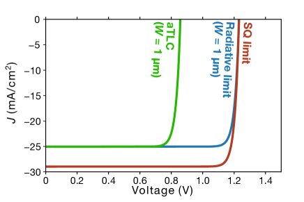
The calculated optical absorption coefficient of CZTS is shown in Fig. 1. Due to the finite absorptivity, the number of absorbed photons and the short-circuit current density decrease (see Fig. 2). However, since CZTS is a direct bandgap semiconductor, the absorption coefficient is high with a sharp onset at the bandgap of . rises rapidly at the bandgap and exceeds , which corresponds to the absorptivity , when the thickness of the absorber is (see Eq. 1). For thickness, the absorptivity is greater than 98%. Thus -thick CZTS exhibits a radiative limit close to the SQ limit, indicating the finite absorption does not limit the efficiency of standard CZTS solar cells, as expected.Siebentritt (2013) The calculated absorption spectra agree well with previous calculationsKato, Nishiwaki, and Fujiwara (2020); Nishiwaki et al. (2018) and experimental resultsNorman et al. (2012); Hirate et al. (2015) except for the Urbach tail as our model does not include the disorder and defects. Note that we do not consider weaker phonon-assisted absorption, which is important in indirect bandgap semiconductors such as Si.Noffsinger et al. (2012); Zacharias, Patrick, and Giustino (2015)
Kesterite solar cells suffer from short carrier lifetime. One contribution to the short carrier lifetime is native bulk defects causing rapid non-radiative recombination. Our previous calculations showed that Sn reduction (Sn(IV) towards Sn(II)) is responsible for both deep levels and large carrier capture cross-sections.Kim, Park, and Walsh (2018); Kim et al. (2019); Li et al. (2019) Moreover, the narrow phase window of kesterites, mainly due to the Zn binary compound, offers little room for defect engineering reducing concentrations of the detrimental defects.
The most detrimental recombination centers have previously been identified as \ceV_S, \ceSn_Zn, and their complexes. The defect concentrations can be tuned through the chemical environment. The best condition is Cu-poor and Zn-rich growth with rich anion incorporation,Dimitrievska et al. (2016) which limits the formation of \ceV_S and \ceSn_Zn. The overall efficiency loss due to the non-radiative recombination was previously estimated to be about 10% using TLC without consideration of finite absorptivity.
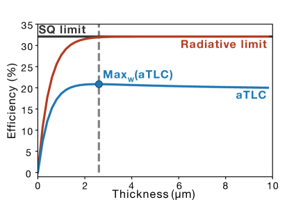
As we combine the non-radiative recombination and the radiative limit, a significant loss is seen (Fig. 2). The efficiency decreases by 9% at the thickness of . For thicker films, both the absorption and the non-radiative losses increase. While the non-radiative recombination current increases linearly with the thickness (Eq.(7), the absorptivity increases rapidly and approaches to unity when the thickness is around . Thus, in this approach, the maximum efficiency of 20.8% is achieved at (see Table 1). We noted that the maximum aTLC values at their optimal thicknesses in Table 1 differ from corresponding TLC valuesKim et al. (2020a) by around 1% due to the aforementioned high absorption coefficient. Further increase in the thickness causes efficiency loss due to enhanced non-radiative recombination.
We note that aTLC still makes a number of strong assumptions that could be loosened to develop more quantitative models. There is an implicit assumption of infinite carrier mobility where the diffusion length does not limit carrier collection. Taking into account finite reflectivity at the top and bottom surfaces, interface recombination, parasitic absorption effect in the window layer, and shunt and series resistance would further improve the predictive power of our approach. Guillemoles et al. (2019) These extensions would come at the cost of increased model complexity and the need to consider specific device architectures.
| FF | Reference | |||||
|---|---|---|---|---|---|---|
| (eV) | (%) | () | () | (%) | ||
| CZTS | 1.50 | 32.1 | 28.9 | 1.23 | 90.0 | SQ limit |
| CZTSe | 1.00 | 31.6 | 47.7 | 0.77 | 85.7 | SQ limit |
| CZGSe | 1.36 | 33.3 | 34.3 | 1.10 | 89.1 | SQ limit |
| AZTSe | 1.35 | 33.7 | 34.7 | 1.09 | 89.0 | SQ limit |
| CZTS | 1.50 | 20.8 | 28.8 | 0.84 | 86.5 | aTLC () |
| CZTSe | 1.00 | 20.6 | 47.7 | 0.53 | 81.2 | aTLC () |
| CZGSe | 1.36 | 23.9 | 34.1 | 0.81 | 86.2 | aTLC () |
| CZTS | 1.50 | 11.0 | 21.7 | 0.73 | 69.27 | Exp.Yan et al. (2018) |
| CZTSe | 1.00 | 11.6 | 40.6 | 0.42 | 67.3 | Exp.Lee et al. (2014) |
| CZTSSe | 1.13 | 12.6 | 35.4 | 0.54 | 65.9 | Exp.Son et al. (2019) |
| CZTGSe | 1.11 | 12.3 | 32.3 | 0.53 | 72.7 | Exp.Kim et al. (2016) |
| CZGSe | 1.36 | 7.6 | 22.8 | 0.56 | 60 | Exp.Choubrac et al. (2018) |
| AZTSe | 1.35 | 5.2 | 21.0 | 0.50 | 48.7 | Exp.Gershon et al. (2016) |
| CZTS:Ag,Cd | 1.40 | 10.1 | 23.4 | 0.65 | 66.2 | Exp.Hadke et al. (2018) |
In conclusion, we have presented an ab initio method for determining the maximum efficiency of a solar cell. The absorption-and-trap-limited conversion efficiency (aTLC), procedure takes into account both radiative and non-radiative recombination. Due to the high optical absorption coefficient of \ceCu2ZnSnS4, the radiative limit approaches the SQ limit with a film thickness of . The increase in non-radiative recombination current through point defects counterbalances this gain of absorption, which decreases the net efficiency of a thick film. We determined the optimal thickness of an absorber layer of a solar cell based on its bulk properties. As such, aTLC can be used a qualitative metric to evaluate and optimise the potential of emerging photovoltaic materials.
Data Availability Statement: The underlying models for capture cross-sections are implemented in the open-source package CarrierCapture.Kim et al. (2020b)
Acknowledgements.
We thank Jose A. Marquez and Thomas Unold for useful discussions and suggesting this extension of TLC. Via our membership of the UK’s HEC Materials Chemistry Consortium, which is funded by EPSRC (EP/L000202), this work used the ARCHER UK National Supercomputing Service (http://www.archer.ac.uk). This research was also supported by the Creative Materials Discovery Program through the National Research Foundation of Korea (NRF) funded by Ministry of Science and ICT (2018M3D1A1058536).References
- Shockley and Queisser (1961) W. Shockley and H. J. Queisser, J. Appl. Phys. 32, 510 (1961).
- Castelli et al. (2012) I. E. Castelli, T. Olsen, S. Datta, D. D. Landis, S. Dahl, K. S. Thygesen, and K. W. Jacobsen, Energy Environ. Sci. 5, 5814 (2012).
- Yu and Zunger (2012) L. Yu and A. Zunger, Phys. Rev. Lett. 108, 068701 (2012).
- Hohenberg and Kohn (1964) P. Hohenberg and W. Kohn, Phys. Rev. 136, B864 (1964).
- Kohn and Sham (1965) W. Kohn and L. J. Sham, Phys. Rev. 140, A1133 (1965).
- Hedin (1965) L. Hedin, Physical Review 139, A796 (1965).
- Park et al. (2018) J.-S. Park, S. Kim, Z. Xie, and A. Walsh, Nat. Rev. Mater. 3, 194 (2018).
- Shockley and Read (1952) W. Shockley and W. T. Read, Phys. Rev. 87, 835 (1952).
- Hall (1952) R. N. Hall, Phys. Rev. 87, 387 (1952).
- Son et al. (2019) D.-H. Son, S.-H. Kim, S.-Y. Kim, Y.-I. Kim, J.-H. Sim, S.-N. Park, D.-H. Jeon, D.-K. Hwang, S.-J. Sung, J.-K. Kang, K.-J. Yang, and D.-H. Kim, J. Mater. Chem. A 132, 17384 (2019).
- Wang et al. (2013) W. Wang, M. T. Winkler, O. Gunawan, T. Gokmen, T. K. Todorov, Y. Zhu, and D. B. Mitzi, Adv. Energy Mater. 4, 1301465 (2013).
- Wong et al. (2019) L. H. Wong, A. Zakutayev, J. D. Major, X. Hao, A. Walsh, T. K. Todorov, and E. Saucedo, J. Phys. Energy 1, 032001 (2019).
- Kim et al. (2020a) S. Kim, J. A. Marquez, T. Unold, and A. Walsh, Energy Environ. Sci. 51, R1 (2020a).
- Chen et al. (2013) S. Chen, A. Walsh, X.-G. Gong, and S.-H. Wei, Adv. Mater. 25, 1522 (2013).
- Hadke et al. (2019) S. Hadke, S. Levcenko, G. Sai Gautam, C. J. Hages, J. A. Márquez, V. Izquierdo-Roca, E. A. Carter, T. Unold, and L. H. Wong, Adv. Energy Mater. 9, 1902509 (2019).
- Giraldo et al. (2019) S. Giraldo, Z. Jehl, M. Placidi, V. Izquierdo-Roca, A. Pérez-Rodríguez, and E. Saucedo, Adv. Mater. 31, 1806692 (2019).
- Grenet et al. (2018) L. Grenet, M. A. A. Suzon, F. Emieux, and F. Roux, ACS Appl. Energy Mater. 1, 2103 (2018).
- Gajdoš et al. (2006) M. Gajdoš, K. Hummer, G. Kresse, J. Furthmüller, and F. Bechstedt, Phys. Rev. B 73, 045112 (2006).
- Blöchl (1994) P. E. Blöchl, Phys. Rev. B 50, 17953 (1994).
- Kresse and D. Joubert (1999) G. Kresse and D. Joubert, Phys. Rev. B 59, 1758 (1999).
- Heyd, Scuseria, and Ernzerhof (2003) J. Heyd, G. E. Scuseria, and M. Ernzerhof, J. Chem. Phys. 118, 8207 (2003).
- Monkhorst and Pack (1976) H. J. Monkhorst and J. D. Pack, Phys. Rev. B 13, 5188 (1976).
- Bystrom et al. (2019) K. Bystrom, D. Broberg, S. Dwaraknath, K. A. Persson, and M. Asta, arXiv.org (2019), 1904.11572v1 .
- Alkauskas, Yan, and Van de Walle (2014) A. Alkauskas, Q. Yan, and C. G. Van de Walle, Phys. Rev. B 90, 075202 (2014).
- Pizzi et al. (2020) G. Pizzi, V. Vitale, R. Arita, S. Blügel, F. Freimuth, G. Géranton, M. Gibertini, D. Gresch, C. Johnson, T. Koretsune, J. Ibañez-Azpiroz, H. Lee, J.-M. Lihm, D. Marchand, A. Marrazzo, Y. Mokrousov, J. I. Mustafa, Y. Nohara, Y. Nomura, L. Paulatto, S. Poncé, T. Ponweiser, J. Qiao, F. Thöle, S. S. Tsirkin, M. Wierzbowska, N. Marzari, D. Vanderbilt, I. Souza, A. A. Mostofi, and J. R. Yates, J. Phys. Condens 32, 165902 (2020).
- Siebentritt (2013) S. Siebentritt, Thin Solid Films 535, 1 (2013).
- Kato, Nishiwaki, and Fujiwara (2020) M. Kato, M. Nishiwaki, and H. Fujiwara, Phys. Rev. Mater. 4, 035402 (2020).
- Nishiwaki et al. (2018) M. Nishiwaki, K. Nagaya, M. Kato, S. Fujimoto, H. Tampo, T. Miyadera, M. Chikamatsu, H. Shibata, and H. Fujiwara, Phys. Rev. Mater. 2, 085404 (2018).
- Norman et al. (2012) A. Norman, D. Levi, F. L. Terry, G. Teeter, H. Du, J. Li, J. Yarbrough, and K. Jones, Opt. Exp. 20, A327 (2012).
- Hirate et al. (2015) Y. Hirate, H. Tampo, S. Minoura, H. Kadowaki, A. Nakane, K. M. Kim, H. Shibata, S. Niki, and H. Fujiwara, J. of Appl. Phys. 117, 015702 (2015).
- Noffsinger et al. (2012) J. Noffsinger, E. Kioupakis, C. G. Van de Walle, S. G. Louie, and M. L. Cohen, Phys. Rev. Lett. 108, 167402 (2012).
- Zacharias, Patrick, and Giustino (2015) M. Zacharias, C. E. Patrick, and F. Giustino, Phys. Rev. Lett. 115, 177401 (2015).
- Kim, Park, and Walsh (2018) S. Kim, J.-S. Park, and A. Walsh, ACS Energy Lett. 3, 496 (2018).
- Kim et al. (2019) S. Kim, J.-S. Park, S. N. Hood, and A. Walsh, J. Mat. Chem. A 7, 2686 (2019).
- Li et al. (2019) J. Li, Z.-K. Yuan, S. Chen, X.-G. Gong, and S.-H. Wei, Chem. Mater. 31, 826 (2019).
- Dimitrievska et al. (2016) M. Dimitrievska, A. Fairbrother, E. Saucedo, A. Perez-Rodriguez, and V. Izquierdo-Roca, Sol. Energy Mater Sol. Cells 149, 304 (2016).
- Guillemoles et al. (2019) J.-F. Guillemoles, T. Kirchartz, D. Cahen, and U. Rau, Nat. Photon. 13, 501 (2019).
- Yan et al. (2018) C. Yan, J. Huang, K. Sun, S. Johnston, Y. Zhang, H. Sun, A. Pu, M. He, F. Liu, K. Eder, L. Yang, J. M. Cairney, N. J. Ekins-Daukes, Z. Hameiri, J. A. Stride, S. Chen, M. A. Green, and X. Hao, Nat. Energy 3, 764 (2018).
- Lee et al. (2014) Y. S. Lee, T. Gershon, O. Gunawan, T. K. Todorov, T. Gokmen, Y. Virgus, and S. Guha, Adv. Energy Mater. 5, 1401372 (2014).
- Kim et al. (2016) S. Kim, K. M. Kim, H. Tampo, H. Shibata, and S. Niki, Appl. Phys. Express 9, 102301 (2016).
- Choubrac et al. (2018) L. Choubrac, G. Brammertz, N. Barreau, L. Arzel, S. Harel, M. Meuris, and B. Vermang, Phys. Status Solidi A 215, 1800043 (2018).
- Gershon et al. (2016) T. Gershon, K. Sardashti, O. Gunawan, R. Mankad, S. Singh, Y. S. Lee, J. A. Ott, A. Kummel, and R. Haight, Adv. Energy Mater 6, 1601182 (2016).
- Hadke et al. (2018) S. H. Hadke, S. Levcenko, S. Lie, C. J. Hages, J. A. Marquez, T. Unold, and L. H. Wong, Adv. Energy Mater. 18, 1802540 (2018).
- Kim et al. (2020b) S. Kim, S. N. Hood, P. van Gerwen, L. D. Whalley, and A. Walsh, J. Open Source Soft. 5, 2102 (2020b).