Refraction of space-time wave packets: I. Theoretical principles
Abstract
Space-time (ST) wave packets are pulsed optical beams endowed with precise spatio-temporal structure by virtue of which they exhibit unique and useful characteristics, such as propagation invariance and tunable group velocity. We study in detail here, and in two accompanying papers, the refraction of ST wave packets at planar interfaces between non-dispersive, homogeneous, isotropic dielectrics. We formulate a law of refraction that determines the change in the ST wave-packet group velocity across such an interface as a consequence of a newly identified optical refractive invariant that we call ‘the spectral curvature’. Because the spectral curvature vanishes in conventional optical fields where the spatial and temporal degrees of freedom are separable, these phenomena have not been observed to date. We derive the laws of refraction for baseband, X-wave, and sideband ST wave packets that reveal fascinating refractive phenomena, especially for the former class of wave packets. We predict theoretically, and confirm experimentally in the accompanying papers, refractive phenomena such as group-velocity invariance (ST wave packets whose group velocity does not change across the interface), anomalous refraction (group-velocity increase in higher-index media), group-velocity inversion (change in the sign of the group velocity upon refraction but not its magnitude), and the dependence of the group velocity of the refracted ST wave packet on the angle of incidence.
I Introduction
‘Space-time’ (ST) wave packets are a class of pulsed optical beams whose spatio-temporal spectra are structured so as to impose a tight association between the spatial and temporal frequencies (or transverse wave-vector components and wavelengths, respectively) Donnelly and Ziolkowski (1993); Longhi (2004); Saari and Reivelt (2004); Kondakci and Abouraddy (2016); Parker and Alonso (2016); Kondakci and Abouraddy (2017); Kondakci et al. (2019); Hall et al. (2021). Engineering this spectral association can yield wave packets that travel rigidly in free space without diffraction or dispersion Reivelt and Saari (2003); Kiselev (2007); Hernández-Figueroa et al. (2008); Turunen and Friberg (2010); Hernández-Figueroa et al. (2014) at an arbitrary group velocity Salo and Salomaa (2001), including Brittingham’s luminal focus-wave mode (FWM) Brittingham (1983), in addition to wave packets whose group velocity takes on superluminal Lu and Greenleaf (1992); Saari and Reivelt (1997); Zamboni-Rached et al. (2002); Recami et al. (2003); Valtna et al. (2007); Zamboni-Rached (2009), subluminal Zamboni-Rached and Recami (2008), or even negative values Zapata-Rodríguez and Porras (2006). Crucially, deviation of the group velocity for ST wave packets in free space from (the speed of light in vacuum) stems from their spatio-temporal field structure and not from chromatic dispersion in the medium.
There has recently been a resurgence of theoretical studies of spatio-temporally structured fields Porras (2017); Efremidis (2017); Wong and Kaminer (2017a, b); Sainte-Marie et al. (2017); Porras (2018); Wong et al. (2020); Kibler and Béjot (2021); Shen et al. (2021); Béjot and Kibler (2021) and newly emerging experimental realizations Froula et al. (2018); Shaltout et al. (2019); Hancock et al. (2019); Jolly et al. (2020); Chong et al. (2020); Chen et al. (2021). We recently introduced a phase-only spatio-temporal spectral synthesis methodology Kondakci and Abouraddy (2017); Yessenov et al. (2019a) that affords precise preparation of ST wave packets. This strategy has facilitated observing substantial and unambiguous departures from conventional behaviors, including propagation invariance Kondakci and Abouraddy (2017, 2018a); Bhaduri et al. (2018, 2019a); Yessenov et al. (2019b); arbitrary group velocities in free space Kondakci and Abouraddy (2019); Yessenov et al. (2019b, 2020a), dielectrics Bhaduri et al. (2019b, 2020), planar waveguides Shiri et al. (2020a), and as surface plasmon polaritons at metal-dielectric interfaces Schepler et al. (2020); self-healing Kondakci and Abouraddy (2018b); time diffraction Porras (2017, 2018); Kondakci and Abouraddy (2018a); Yessenov et al. (2020b); axial acceleration and deceleration Yessenov and Abouraddy (2020); and arbitrary dispersion in free space Yessenov et al. (2021).
Exploring the interaction of ST wave packets with photonic devices necessitates understanding their refraction at planar interfaces. Following the classification scheme of ST wave packets in Ref. Yessenov et al. (2019c), we distinguish between three families: baseband, X-waves, and sideband (e.g., FWMs) – which are expected to exhibit distinct refractive behavior by virtue of their spatio-temporal structure. To date, there have been only a few theoretical studies of the refraction of X-waves Shaarawi et al. (2000); Attiya et al. (2001); Shaarawi et al. (2001); Salem and Baǧcı (2012) and FWMs Hillion (1993); Donnelly and Power (1997); Hillion (1998, 1999), which focused on modifications occurring in their reflected or refracted spatio-temporal profiles. However, no new refractive phenomena unique to these ST wave packets were unveiled, and no experimental investigations were reported.
Using our versatile synthesis strategy, we recently reported an initial experimental study of the refraction of baseband ST wave packets at a planar interface between two non-dispersive, homogeneous, isotropic dielectrics Bhaduri et al. (2020). By identifying a new optical invariant quantity (which we denote the ‘spectral curvature’) that is unchanged upon traversing planar interfaces between pairs of such media, we uncovered a new law governing the change in the group velocity of refracted ST wave packets. In turn, this helps unveil new refractive phenomena exhibited by baseband ST wave packets – even at normal incidence. First, for any two dielectrics regardless of their index contrast, there always exists a ST wave packet whose group velocity is invariant across the interface. Second, there exists a regime of anomalous refraction whereby the group velocity of the ST wave packet increases when traversing an interface from low to high index. Third, there always exists a ST wave packet whose group-velocity magnitude does not change, but whose sign switches after traversing the interface, leading to group-delay cancellation when this ST wave packet traverses two equal-thickness layers of these materials. Finally, at oblique incidence, the group velocity of the transmitted ST wave packet changes with the angle of incidence at the interface Bhaduri et al. (2020). These surprising features highlight some of the rich physics underpinning the refraction of ST wave packets.
Outline of this paper sequence
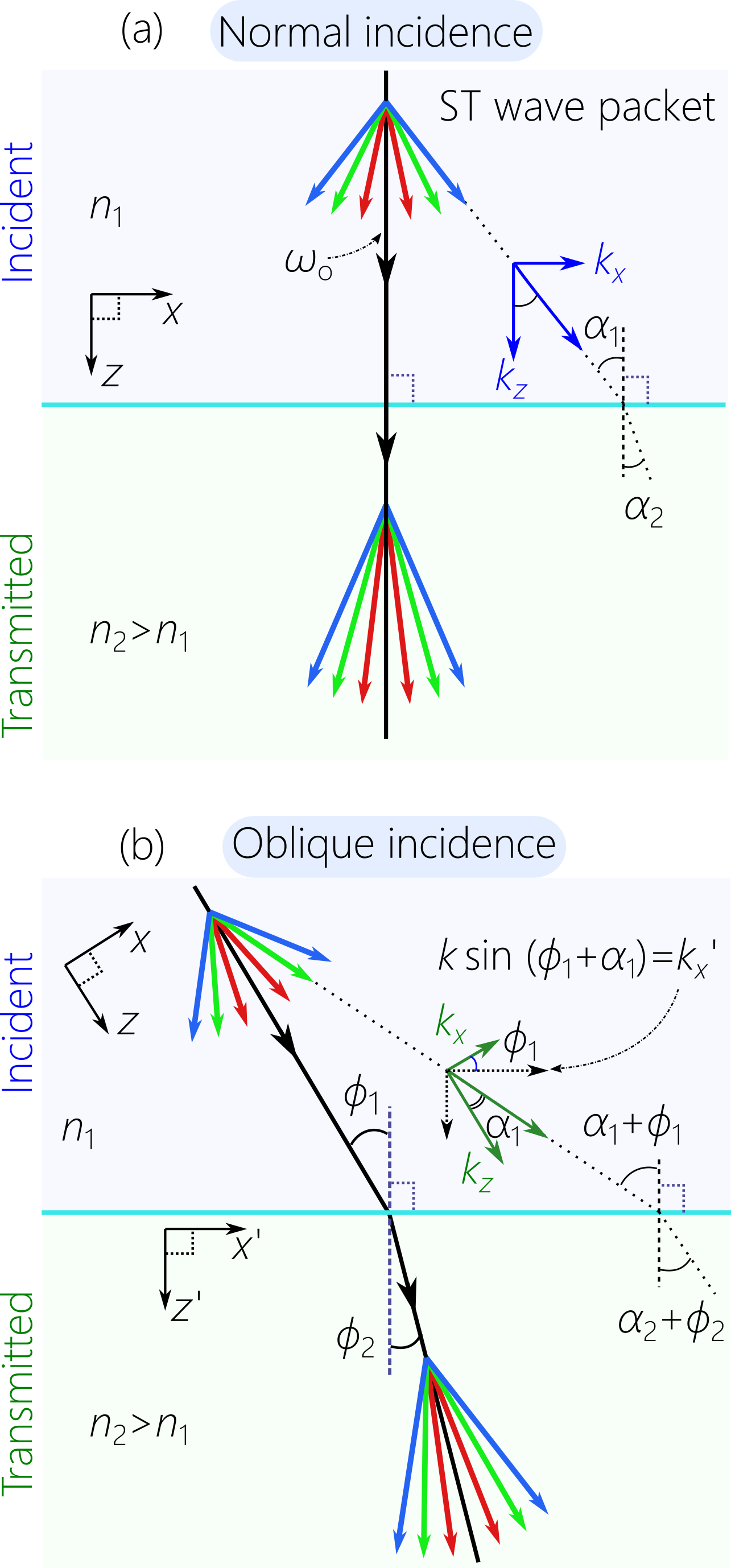
In this paper, and in two accompanying papers, we present a detailed theoretical and experimental study of the refraction of ST wave packets at a planar interface between two non-dispersive, homogeneous, isotropic dielectrics [Fig. 1]. This paper sequence provides a comprehensive study that extends beyond that in Bhaduri et al. (2020), which was restricted to an initial investigation of only baseband ST wave packets. In contrast, we examine here all families of ST wave packets, including FWMs and X-waves (however, when unspecified, ST wave packets will refer to the baseband class). Hereon, we refer to these papers with Roman numerals (I), (II), and (III).
We first distinguish between intrinsic and extrinsic degrees of freedom (DoFs) in the optical field. Examples of extrinsic DoFs of a wave packet are its central wavelength, spatial and temporal bandwidths, direction of propagation, and spatio-temporal profile. Intrinsic DoFs, on the other hand, are related to the internal geometry of the field itself and are in principle independent of these extrinsic DoFs. For ST wave packets, we identify the ‘spectral tilt angle’ as an intrinsic DoF of relevance to their refraction Yessenov et al. (2019a). This quantity is related to the curvature of its spatio-temporal spectrum, which determines the wave packet group velocity. In principle, the spectral tilt angle is independent of all the external DoFs.
Whereas Snell’s law governs the change in an external DoF (the direction of propagation), the laws of refraction we examine in this paper sequence concern the change in an internal DoF; namely, the spectral tilt angle . It is crucial to note here that the deviation of in a non-dispersive medium from is dictated by the spectral tilt angle, . We aim to formulate a relationship between the group velocity (or group index ) in the first medium and the corresponding quantities ( and ) in the second upon normal or oblique incidence at a planar interface [Fig. 1].
Snell’s law stems from the invariance of the transverse component of the wave vector and the optical frequency across the interface. These conservation laws allow us to identify a quantity characteristic of ST wave packets that is invariant across planar interfaces, which we denote the ‘spectral curvature’. Our approach is closest to that in Ref. Donnelly and Power (1997), which in turn is based on the pioneering work on the spatio-temporal spectral representations of ST wave packets on the light-cone Donnelly and Ziolkowski (1993). As mentioned above, previous theoretical studies of the refraction of ST wave packets focused on the changes in the spatio-temporal profiles (an extrinsic DoF). The spectral curvature and the spectral tilt angle are intrinsic DoFs that are independent of the wave packet profile. Indeed, although the refracted wave packet profile may undergo changes (e.g., due to the Fresnel coefficients), these do not affect our conclusions.
The content of the papers in this sequence can be summarized as follows.
Paper (I)
We lay out in paper (I) the theoretical foundations for the experimental work that will be reported in (II) and (III). First, we review of the formulation of ST wave packets in a dielectric and their spectral representation on the surface of the light-cone, which is a useful tool to help visualize the spatio-temporal spectral dynamics upon refraction. We next derive the laws of refraction at normal incidence for all three families of ST wave packets: baseband, sideband (FWMs), and X-waves Yessenov et al. (2019c). More emphasis is placed on the first because they exhibit the most interesting refractive phenomena and because of the difficulty in synthesizing X-waves and FWMs Yessenov et al. (2019c). We then formulate a law of refraction at oblique incidence for baseband ST wave packets; a similar law cannot be devised for X-waves or sideband ST wave packets.
Paper (II)
In paper (II) we confirm experimentally the novel refractive phenomena associated with baseband ST wave packets at normal incidence [Fig. 1(a)] using a variety of optical materials with refractive indices in the range , including MgF2, UV fused silica, BK7 glass, and sapphire. We report observations of the novel refractive phenomena predicted in paper (I): (1) group-velocity invariance; (2) the transition from normal to anomalous refraction; and (3) group-velocity inversion and group-delay cancellation. We also provide a description of the dynamics of the spectral support domain of ST wave packets on the light-cone, which elucidates the counter-intuitive transition from normal to anomalous refraction.
Paper (III)
In paper (III) we examine the refraction of baseband ST wave packets at oblique incidence [Fig. 1(b)]. We verify experimentally the modified law of refraction that accounts for oblique incidence and show how the group velocity of the transmitted ST wave packet changes with the angle of incidence while holding all other variables fixed. We then examine how this effect can be exploited in a scheme for blindly synchronizing multiple receivers at different a priori unknown distances beyond an interface between different media. A first experimental test of this blind synchronization scheme is reported.
II Space-time wave packets in a non-dispersive dielectric
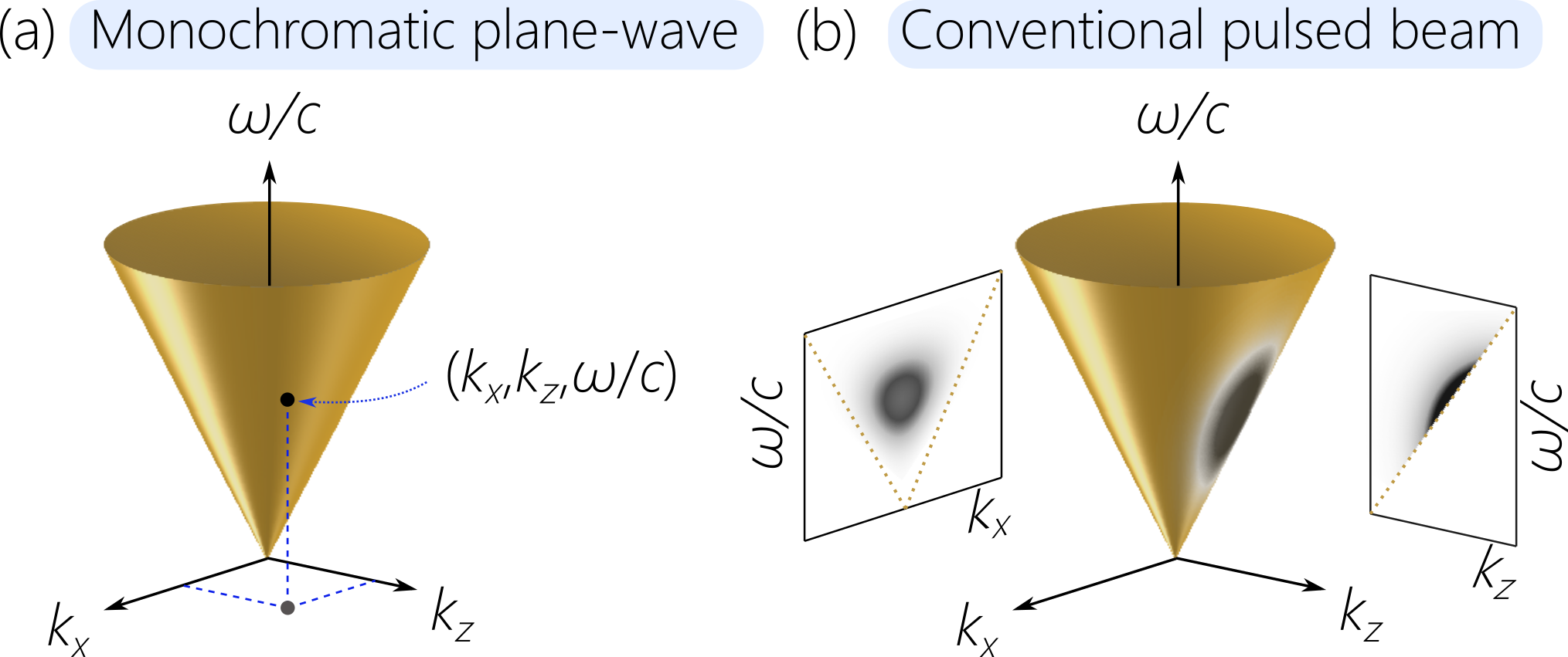
ST wave packets are distinguished from conventional pulsed beams by being endowed with a precise spatio-temporal structure, which is best elucidated in the spectral domain Donnelly and Ziolkowski (1993); Saari and Reivelt (2004); Kondakci and Abouraddy (2016); Efremidis (2017). We consider optical fields described by one transverse coordinate , the axial coordinate , and time (the field is uniform along , which simplifies the analysis and the experiments without loss of generality). The angular frequency is referred to as the temporal frequency to symmetrize the nomenclature with respect to the spatial frequency , which is the transverse component of the wave vector (the axial component is ). In a non-dispersive, homogeneous, isotropic dielectric of refractive index , the dispersion relationship is , which corresponds to the surface of a light-cone of opening angle . A monochromatic plane wave is represented by a point on the light-cone surface [Fig. 2(a)]. The envelope of a pulsed field can be decomposed into an angular spectrum Saleh and Teich (2019):
| (1) |
where the spatio-temporal spectrum is the two-dimensional Fourier transform of , is the central frequency, is the corresponding free-space wave number, and . A conventional pulsed beam of spatial bandwidth and temporal bandwidth is represented by a two-dimensional (2D) domain on the surface of the light-cone [Fig. 2(b)]. In most conventional pulsed laser beams, the spatio-temporal spectrum is approximately separable with resepct to the spatial and temporal DoFs, .
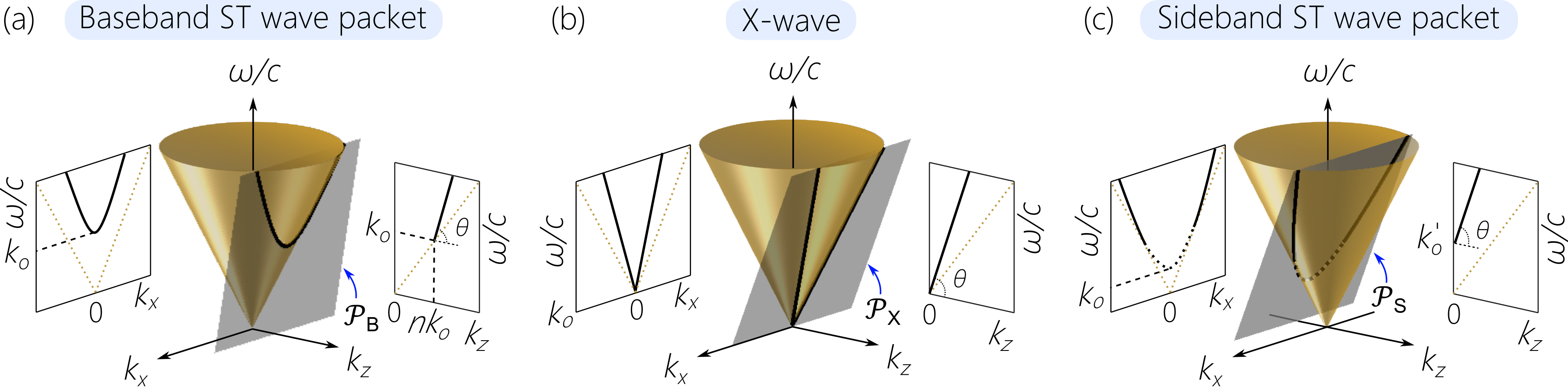
For ST wave packets, the spectral support domain of is no longer 2D. Rather, it is reduced to one dimension (1D) by enforcing an association between the spatial and temporal frequencies such that , where is a deterministic mapping that dictates the functional dependence between and , and is a real continuous parameter identifying this association Donnelly and Ziolkowski (1993); Longhi (2004); Saari and Reivelt (2004); Kondakci and Abouraddy (2017). In other words, angular dispersion is introduced into the field Torres et al. (2010); Fülöp and Hebling (2010); Hall et al. (2021); Yessenov et al. (2021). To achieve propagation invariance, must impose the constraint , where is a constant and is the group velocity. In other words, the spectral support domain corresponds to the intersection of the light-cone with a plane that is parallel to the -axis. Propagation-invariant wave packets can be classified into three distinct families Yessenov et al. (2019c): baseband ST wave packets Kondakci and Abouraddy (2016); Parker and Alonso (2016); Kondakci and Abouraddy (2017), X-waves Saari and Reivelt (1997), and sideband ST wave packets Brittingham (1983); Reivelt and Saari (2000, 2002). In all cases, the wave packet travels rigidly at a group velocity and group index , where (the spectral tilt angle) is the angle makes with respect to the -axis Yessenov et al. (2019c, b, a).
II.1 Baseband ST wave packets
Baseband ST wave packets are so-called because temporal frequencies in the vicinity of the carrier frequency are associated with spatial frequencies in the vicinity of . This class of ST wave packets is identified with a plane having the form , which passes through the point and intersects with the light-cone in the conic section [Fig. 3(a)]:
| (2) |
As such, the envelope of the ST wave packet takes on the form
| (3) |
where is the Fourier transform of . Subluminal propagation in a medium of index (, ) is associated with the range , and superluminal propagation (, ) with , which includes a negative- regime (, ) when . The luminal condition (, ) corresponds to tangential to the light-cone, whereupon , and the conic section degenerates into a line () representing a pulsed plane-wave. The continuous accessibility of group velocity values by tuning Kondakci and Abouraddy (2017); Yessenov et al. (2019a); Kondakci and Abouraddy (2019) makes baseband ST wave packets most interesting with respect to refraction. Crucially, the group velocity of these wave packets is the speed of their peak Shaarawi and Besieris (2000); Saari (2018); Saari et al. (2019); Saari and Besieris (2020).
II.2 X-waves
The spectral support domain of X-waves comprises the two straight lines at the intersection of the light-cone with the plane that passes through the origin , such that ,
| (4) |
see Fig. 3(b). Only positive-valued superluminal group velocities (, ) are allowed Yessenov et al. (2019c). The luminal condition corresponds to , similarly to baseband ST wave packets, whereupon the X-wave degenerates into a pulsed plane-wave.
II.3 Sideband ST wave packets
In sideband ST wave packets, the spatial frequencies in the vicinity of are physically forbidden because they are associated with negative-valued , which are incompatible with causal excitation and propagation Yessenov et al. (2019c). The spectral support domain here is the conic section at the intersection of the light-cone with a plane given by [Fig. 3(c)]:
| (5) |
This conic section is a hyperbola when (superluminal), and an ellipse when (subluminal). Although this ellipse can be shown to correspond to that of subluminal baseband ST wave packets after an appropriate transformation Yessenov et al. (2019c), we nevertheless distinguish here between the two. For subluminal baseband ST wave packets, the spectral support domain is localized at , whereas that for subluminal sideband ST wave packets is localized away from . Uniquely, the luminal condition is not a plane-wave pulse, but rather corresponds to Brittingham’s FWM Brittingham (1983) represented by a parabola, . Increasing produces positive-valued superluminal sideband ST wave packets (or ‘focus-X-waves’ Besieris et al. (1998)). The selection of the spectral plane results in a negative phase velocity Bélanger (1984), and the envelope is given by the same relationship in Eq. 3, except that the association between the spatial and temporal frequencies is determined through Eq. 5, and is defined only over the range whereupon and Yessenov et al. (2019c).
III Law of refraction for space-time wave packets
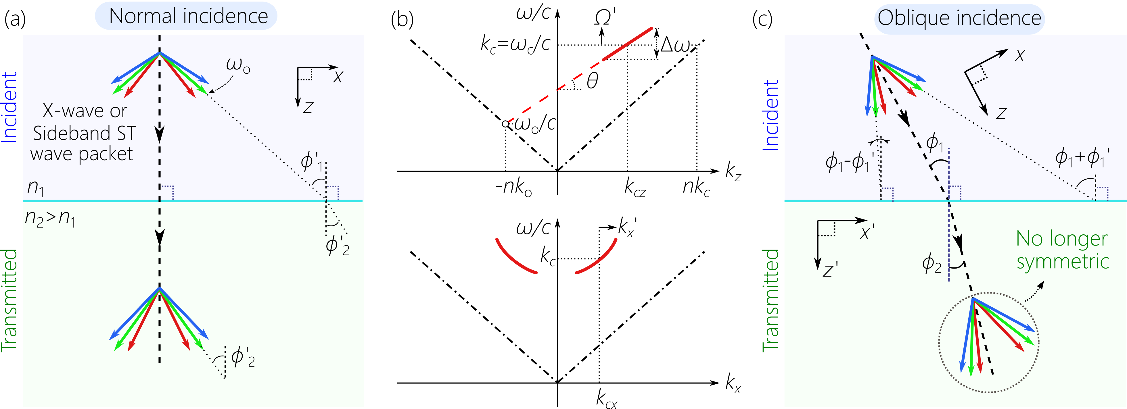
Even at normal incidence, where the central wave vector (corresponding to ) is orthogonal to the interface, there is always a finite span of angles of incidence involved because the ST wave packet has a finite spatial bandwidth [Fig. 1(a)]. Relying on the conservation of energy and transverse momentum across a planar interface ( and are invariant, respectively), we identify in the following sections a spatio-temporal refractive invariant quantity that characterizes the spectral projection onto the -plane. We make use of the relationships between and for baseband ST wave packets in Eq. 2, X-waves in Eq. 4, and sideband ST wave packets in Eq. 5 to derive this refractive invariant for each family. With the help of such invariants, we establish the relationship between the group velocity (group index or spectral tilt angle ) of the incident ST wave packet and the corresponding quantities (, , or ) in the second. Within this conception, the group velocity of the transmitted wave packet depends not only on the refractive indices and , but also on the group velocity of the incident wave packet . This is of course altogether different from the usual scenario for refraction in non-dispersive media where the group velocities are determined solely by the refractive indices ( and ) and there is no influence from the group velocity of the incident wave packet on that of the transmitted.
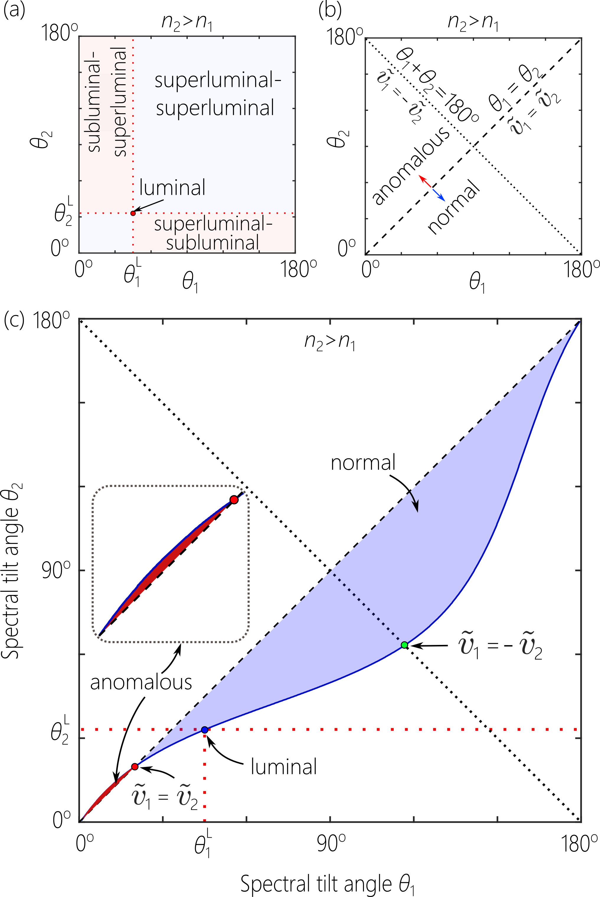
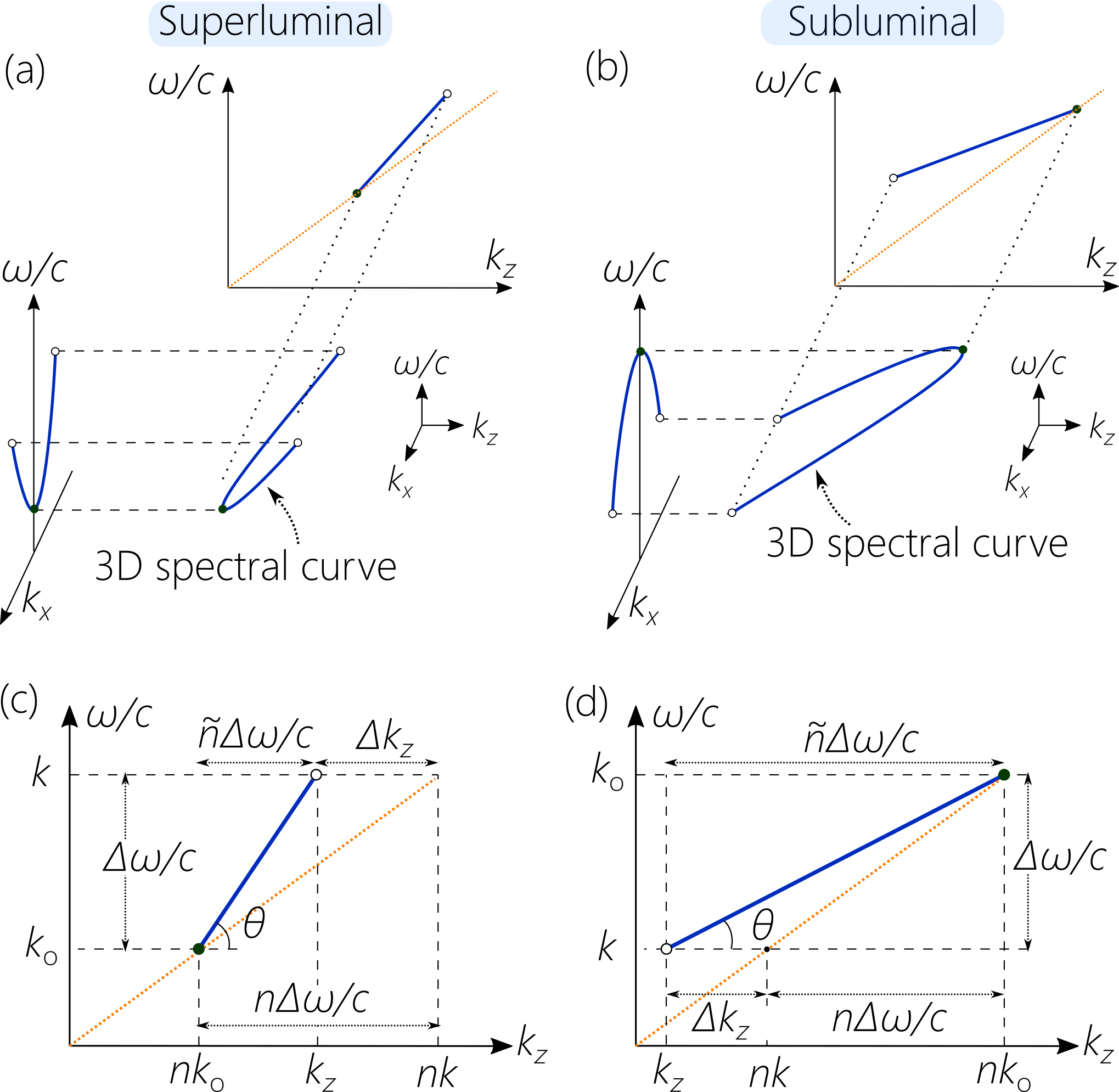
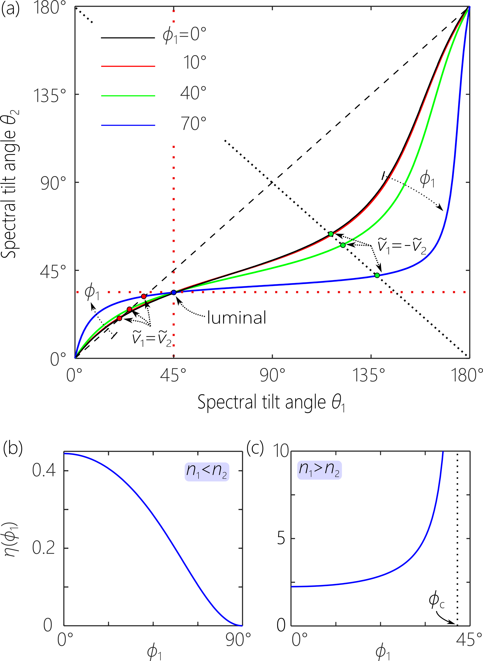
It is convenient to plot the relationships we derive in the domain [Fig. 4], where each family of ST wave packets is represented by a 1D curve that passes through the point ; here is the spectral tilt angle for the luminal condition in the first medium , and in the second . This condition delineates the superluminal/subluminal combinations in the two media [Fig. 4(a)]. For example, any point in the upper-right quadrant of Fig. 4(a) represents a wave packet that is superluminal in both media, whereas a point in the quadrant below it represents a wave packet that is superluminal in the first medium, but becomes subluminal after refraction in the second. The diagonal line divides the domain into normal and anomalous refraction regimes [Fig. 4(b)]. Assuming that , then the upper half corresponds to anomalous refraction (i.e., despite ), and the lower half to normal refraction (i.e., as expected when ). Conversely, when , then the upper half of the domain above the diagonal corresponds to normal refraction and the lower half to anomalous refraction.
The point at the intersection of the curve representing the law of refraction with the diagonal corresponds to group-velocity invariance: the group velocity of the incident wave packet represented by this point is equal to that of the transmitted wave packet , independently of the index contrast [Fig. 4(b)]. Furthermore, the point at the intersection of the law-of-refraction curve with the anti-diagonal corresponds to group-velocity inversion: the group velocity of the transmitted wave packet has the same magnitude but opposite sign of that of the incident wave packet [Fig. 4(b)]. Switching the direction of incidence (from to ) results in reflecting the curve representing the law of refraction (from to ) around the diagonal . Note that the representation of refraction at normal incidence for a conventional collimated field corresponds to the point at , and none of the phenomena we proceed to describe therefore occur in this scenario.
IV Normal incidence of baseband space-time wave packets
IV.1 Law of refraction
Assuming narrow temporal and spatial bandwidths, and , respectively, the exact conic section for baseband ST wave packets in Eq. 2 can be approximated in the vicinity of by a parabola,
| (6) |
The invariance of and across the planar interface indicates that the quantity is a new optical refractive invariant, which is related to the curvature of the parabolic spatio-temporal spectrum in Eq. 6. We henceforth refer to this quantity as the ‘spectral curvature’. From this invariant, we formulate the law of refraction at normal incidence for baseband ST wave packets:
| (7) |
This equation describes the change to the group index (and thus the group velocity and the spectral tilt angle ) across the interface. The group index of the transmitted wave packet depends on , , and the group index of the incident wave packet . We plot in Fig. 4(c) this law of refraction for and , but the main features of the plotted curve are generic for all pairs of values for and .
IV.2 Physical interpretation of the refractive invariant
The physical interpretation of the quantity can be elucidated by examining the spectral support domain projected onto the -plane. Starting from the dispersion relationship , the paraxial and narrow-bandwidth approximations yield:
| (8) |
When , the projected spectrum lies along the light-line , corresponding to a plane-wave pulse whose group velocity is . Introducing a finite spatial frequency into any plane-wave shifting the point representing its projection away from the light-line. The extent of this shift is determined by the magnitude of and the refractive index as seen from the term in Eq. 8. This is because the curvature of the light-cone is determined by , and this curvature dictates the change in in response to a change in ; see Fig. 5(a,b).
So far, we have not involved the unique constraint associated with baseband ST wave packets. Now consider two plane-waves, one at a temporal frequency that lies on the light-line ( and ), and another at that does not ( and ); see Fig. 5(c). We define the deviation of the latter plane wave from the light-line as . If these two plane waves are the end points for the spectrum of a superluminal baseband ST wave packet, then the plane waves lying between and are projected onto the straight light joining these two and tilted by an angle with respect to the -axis. In this case , where , the group velocity is , and is the temporal bandwidth. Therefore, the term represents the deviation in wave-packet group velocity from the luminal limit. However, the quantity is not invariant with respect to changes in . Nevertheless, because and are invariant across a planar interface, we identify instead the quantity as a refractive invariant. In other words, when traversing a planar interface between two media of refractive indices and , the quantities and associated with the incident and transmitted wave packets are equal. Although the refractive index of the medium is different, changes with respect to to maintain this quantity fixed. This analysis assumed a superluminal ST wave packet () [Fig. 5(a,c)], but a similar logic applies to the subluminal case () [Fig. 5(b,d)].
This new refractive invariant is a product of two terms: (1) the term that arises from the constraint unique to ST wave packets, and represents the extent of the deviation away from the light-line (and thus the deviation of the group velocity from ); and (2) the term arising from the curvature of the light-cone surface, which dictates the degree to which the spatial frequencies can produce a deviation from the light-line. This invariant quantity is the inverse of the curvature of the spectral projection of the ST wave packet onto the -plane in the vicinity of . For conventional pulsed beams in a non-dispersive medium, and the spectral curvature therefore vanishes. Consequently, this refractive invariant quantity has not had impact on optical refraction to date.
IV.3 Consequences of the law of refraction
Despite the simplicity of the law of refraction in Eq. 7, it nevertheless reveals several surprising physical consequences.
IV.3.1 Luminal wave packets remain luminal
If the incident wave packet is luminal (i.e., a plane-wave pulse), the transmitted wave packet remains luminal in the second medium with (i.e., remains a plane-wave pulse), as confirmed by direct substitution in Eq. 7. Furthermore, if the incident wave packet is subluminal (superluminal ), then it remains subluminal (superluminal ). The subluminal-superluminal and superluminal-subluminal regimes in Fig. 4(c) are forbidden. In other words, refraction of ST wave packets does not bridge the subluminal/superluminal barrier.
IV.3.2 Group-velocity invariance
Can the group velocity of a ST wave packet remain unchanged after traversing the interface? Although this is impossible for conventional pulses, Eq. 7 indicates that setting the group indices in the two media equal yields a solution:
| (9) |
That is, a normally incident ST wave packet with group index will be transmitted without changing its group index – independently of the contrast between and . Because , such a ST wave packet is subluminal in both media. This condition corresponds to the point at the intersection of the curve in -space representing Eq. 7 with the diagonal [Fig. 4(b,c)].
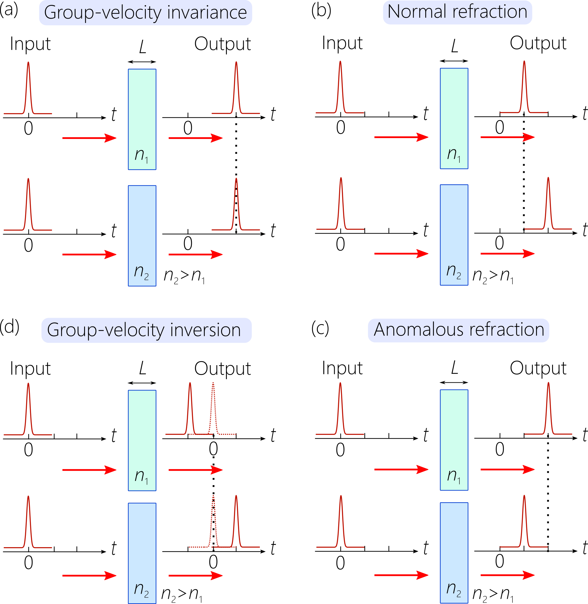
We can view this phenomenon from a different perspective. If we assume incidence on either medium or from an ambient medium of index , then we have and , where is the group index of the ST wave packet in the ambient medium. If , then the threshold condition corresponds to . Such a wave packet incident from free space on layers of indices and of equal thickness incurs the same group delay ; see Fig. 6(a).
IV.3.3 Anomalous refraction
The group index is a threshold that separates regimes of normal and anomalous refraction. For , substitution of (, where ) for the incident ST wave packet in Eq. 7 shows that the group velocity of the transmitted wave packet is lower than that of the incident wave packet, as expected when . Indeed, the corresponding segment of the curve representing the law of refraction for is below the diagonal in Fig. 4(c), thereby indicating normal refraction [Fig. 6(b)]. That is, the group velocity drops in the higher-index medium.
On the other hand, when the incident ST wave packet is such that (), the opposite behavior emerges: the group velocity anomalously increases in the higher-index medium. The corresponding segment of the curve representing the law of refraction for is above the diagonal in Fig. 4(c), thereby indicating anomalous refraction [Fig. 6(c)]. That is, the group velocity increases in the higher-index medium. To the best of our knowledge, this type of behavior has never been identified or demonstrated in non-dipsersive dielectrics.
IV.3.4 Group-velocity inversion and group-delay cancellation
In the superluminal regime , refraction of ST wave packets is always normal. However, because baseband ST wave packets admit both positive- and negative-valued group velocities, the curve representing Eq. 7 in the domain in Fig. 4(c) intersects with the anti-diagonal . At this intersection point ; i.e., the magnitude of the group index of the incident wave packet remains constant upon transmission, but its sign is flipped. This condition occurs when
| (10) |
and direct substitution into Eq. 7 yields . We refer to this condition as group-velocity inversion. In such a scenario, the group delay incurred by the ST wave packet is zero when traversing a bilayer formed of equal-thickness layers of indices and when the group index in the first layer is . We denote this scenario group-delay cancellation [Fig. 6(d)]. Considering incidence from an ambient medium of index , then a wave packet having group index will incur a delay when normally incident on a layer of thickness and index , and a delay when incident on a layer of equal thickness and index .
A similar effect can be realized for unequal layer thicknesses and of refractive indices and , respectively. Group-delay cancellation occurs when , which necessitates the use of an incident wave packet whose group index is , for which the transmitted wave packet has a group index . When incident from free space, the required group index is .
IV.4 GVD for large bandwidths
The parabolic approximation in Eq. 6, leading to the law of refraction in Eq. 7, was derived under the assumption of narrow spatial and temporal bandwidths. Violating this assumption (e.g., due to a broad spatio-temporal bandwidth) does not invalidate Eq. 7, which still dictates the change in . However, in addition to the change in , the transmitted ST wave packet experiences group velocity dispersion (GVD) in the second medium. To estimate this GVD, we obtain the axial wave number in the second medium in terms of , , and . Subtracting the equations for the light-cones in the two media and and then substituting for , we obtain this exact relationship:
| (11) |
We expand in the vicinity of ():
| (12) |
The zeroth-order term is , whereas the first-order term is , corresponding to the law of refraction in Eq. 7. Defining the GVD parameter , we have:
| (13) |
Therefore, GVD increases with: (1) the index contrast between and ; (2) the deviation of the group index in the first medium from the luminal condition; and (3) the wavelength . The GVD is normal () when and is anomalous () when . The value of (for fixed and ) reaches a maximum value when given by
| (14) |
V Normal incidence of X-waves
V.1 Law of refraction
Starting from Eq. 4 for a X-wave, we can easily identify the refractive invariant quantity . This invariant for X-waves is exact and independent of bandwidth because the spectral projections are straight lines. We can thus formulate the following law of refraction at normal incidence for X-waves:
| (15) |
which is plotted in Fig. 7 (dashed curve). Because only positive-valued superluminal group velocities are accessible , the axes for and in Fig. 7 extend only to .
Practically, we expect that and ; i.e., there is always only a minute deviation in group velocity from the luminal limit. In fact, previous experiments have reported group velocities of X-waves in free space of Bowlan et al. (2009); Bonaretti et al. (2009); Kuntz et al. (2009) (confirmed also in Yessenov et al. (2019c)). This is a fundamental limitation for X-waves that cannot be overcome within paraxial optics. Indeed, if we take (where ), then the deviation from the luminal condition is . For , which approaches the limit of paraxial optics, we have in free space. Realizing a X-wave whose group velocity deviates appreciably from therefore requires operating deep within the non-paraxial regime.
V.2 Consequences of the law of refraction
It is important to note that normal incidence of a X-wave is only nominal. In contrast to baseband ST wave packets where the plane-wave component at is normally incident on the interface, the component at for a X-wave is not associated with , and is not normally incident; see Fig. 8(a). Indeed, the angle of incidence of in a medium of index is given by [Fig. 8(a)]. For this effective incident angle to reach the critical condition for total internal reflection (when ) requires an extreme non-paraxial scenario, and we can safely ignore this possibility. Finally, as a result of the exact formulation of the law of refraction for X-waves (independently of bandwidth) GVD never arises for X-waves upon refraction at normal incidence. Although the law of refraction here is a quadratic equation, the relationship between and is monotonic over the allowable range, with reaching a minimum value of at () [Fig. 7].
V.2.1 The luminal wave packet remains luminal
Because the luminal limit for a X-wave is a plane-wave pulse (), the invariance of implies that a luminal X-wave remains luminal. Indeed, the luminal limits for baseband ST wave packets and X-waves coincide.
V.2.2 Normal refraction
The law of refraction for normally incident X-waves in Eq. 15 indicates that their refraction is always normal: the group velocity always drops when traveling to a higher-index medium and increases when traveling to a lower-index medium, just as with conventional pulses. In other words, if , then . This is seen in Fig. 7 by noting that the entire curve representing the law of refraction lies below the diagonal . As a result, the phenomena described above for baseband ST wave packets, including group-velocity invariance and anomalous refraction, do not occur with X-waves. Moreover, group-velocity inversion does not occur because X-waves are restricted to positive-valued group velocities.
VI Normal incidence of sideband space-time wave packets
VI.1 Law of refraction
It is more difficult to formulate a law of refraction for sideband ST wave packets (e.g., FWMs) because the spatial frequencies in the vicinity of are forbidden on physical grounds, thereby precluding the parabolic approximation used for baseband ST wave packets. Instead, the spectral plane intersects with the light-cone in a conic section and the support domain corresponds to large values of , which can even be comparable to (i.e., non-paraxial); see Fig. 3(c).
Nevertheless, an approximation can be formulated in the limit of a narrow spectral bandwidth. Unlike baseband ST wave packets and X-waves, the frequency does not belong to the spectrum of sideband ST wave packets. Assume a center frequency and narrow bandwidth . Define the wave number , and the transverse and axial components and , respectively, with ; see Fig. 8(b). The narrow temporal bandwidth implies also a narrow spatial bandwidth . Starting from the exact conic section in Eq. 5, expanding the temporal frequency and the spatial frequency , with and , and retaining terms that are first-order in and yields a refractive invariant,
| (16) |
where is a dimensionless parameter close to unity. This refractive invariant is the slope of the spectral projection of the ST wave packet onto the -plane. From this invariant quantity, we obtain a law of refraction for sideband ST wave packets at normal incidence [Fig. 7]:
| (17) |
The parameter is limited to the range . At its maximum value ( or ), the wave packet reverts to a X-wave, and the law of refraction in Eq. 17 simplifies to that in Eq. 15 for X-waves. The minimal value corresponds to and , whereupon . In general, the axial wave number is a fraction of the total wave number in the medium , with . It is easy to show that
| (18) |
which implies an additional constraint in the superluminal regime (it is always satisfied in the subluminal regime). Therefore, remaining within paraxial limits ( and ) necessitates staying close to the luminal condition ().
To the best of our knowledge, there have been no reported measurements of the group velocity of sideband ST wave packets. Indeed, the conditions for producing a deviation from here are even more stringent than those for X-waves. If the center frequency of the spectrum is , then the deviation in group velocity from the luminal condition in free space is , where and is the deviation for a X-wave of similar spatial bandwidth. As such, a sideband ST wave packet will be even closer to the luminal limit than a X-wave of similar spatial bandwidth.
VI.2 Consequences of the law of refraction
Although the equation representing the law of refraction for sideband ST wave packets is quadratic, nevertheless the relationship between and is monotonic because the constraint restricts the valid domain in -space to that above the dotted curve () in Fig. 7.
Similarly to X-waves, the central frequency for a sideband ST wave packet is not normally incident on the interface [Fig. 8(a)], but instead makes an angle with respect to the normal to the interface, where
| (19) |
the second term in this expression vanishes for X-waves. The minimal value of (maximum value for ) leads to (), which is far from the paraxial regime as expected. We emphasize that the findings discussed below for sideband ST wave packets are only valid for narrow bandwidths.
VI.2.1 Group-velocity invariance
The law of refraction in Eq. 17 has two solutions for group-velocity invariance . The first is the trivial solution ; the second is at a negative-valued group index , which is excluded. Therefore, similarly to X-waves, sideband ST wave packets do not exhibit group-velocity invariance and their refraction is therefore always normal [Fig. 7]. Furthermore, because only positive-valued group velocities can be realized, group-velocity inversion and group-delay cancellation are also precluded
VI.2.2 Bridging the subluminal-superluminal barrier
Unlike baseband ST wave packets and X-waves, where a luminal incident wave packet remains luminal, a luminal sideband ST wave packet (i.e., a FWM) does not remain luminal upon transmission. This is confirmed by setting (a luminal FWM) in Eq. 17, whereupon ; where . As such ; i.e., the transmitted wave packet is not luminal. Indeed, assuming , we have so that the transmitted wave packet is subluminal, as expected in the normal refraction regime. As increases (thus becoming superluminal), also increases until it reaches the luminal value of when .
As increases further, also increases until it formally reaches a maximum value when , followed by a drop in with further increase in beyond this value. However, this regime is inaccessible because of the abovementioned limit set on the minimum value of . Indeed, reaching the peak in as increases requires , which is not admissible [Fig. 7]. The minimal value of imposes a minimum achievable value at any given by
| (20) |
The dotted curve in Fig. 7 corresponds to this equation. It can be easily confirmed that setting () results in , which coincides with the X-waves limit; and setting the luminal limit for FWMs results in .
VII Oblique incidence of baseband space-time wave packets
Although the transverse momentum is invariant across the planar interface, at oblique incidence the transverse component of the wave vector with respect to the propagation axis of the ST wave packet is not parallel to the interface [Fig. 1(b)]. If , where is measured with respect to the incident propagation direction, , and is the angle of incidence with respect to the normal to the interface, then the invariant transverse momentum with respect to the interface is , whereupon ; see Fig. 1(b). We place no restriction on the value of , but we retain the small-bandwidth approximation for the ST wave packets, ( and ), so that . Because (Snell’s law) and , we have . Referring to Eq. 6, the invariance of and across the interface imply that the quantity is the new refractive invariant at oblique incidence, from which we formulate the modified law:
| (21) |
This relationship reverts to Eq. 7 at normal incidence.
VII.1 Consequences of the law of refraction
The consequences of normal-incidence refraction for baseband ST wave packets are retained at oblique incidence after the appropriate modifications. First, luminal wave packets remain luminal at oblique incidence; i.e., still entails that . Second, the group index for group-velocity invariance is
| (22) |
In other words, the invariant group velocity is higher at oblique incidence. The onset of anomalous refraction can thus be tuned by changing the angle of incidence [Fig. 9(a)]. Third, the condition for group-velocity inversion at oblique incidence is:
| (23) |
When , we have , so that the incident group velocity at which group-velocity inversion occurs increases. The opposite occurs when , whereupon and the value of the incident group velocity at which group-velocity inversion occurs decreases. The condition in Eq. 23 guarantees group-velocity inversion but not group-delay cancellation because at oblique incidence the propagation distances are not equal in two equal-thickness layers, which necessitates modifying Eq. 23 to accommodate the path-length difference in the two layers.
VII.2 Dependence of the transmitted-wave-packet group velocity on angle of incidence
A unique consequence of refraction at oblique incidence is that the group velocity in the second medium can be tuned by changing the angle of incidence (at fixed ). By rewriting the law of refraction in Eq. 21, , dictates through the function given by:
| (24) |
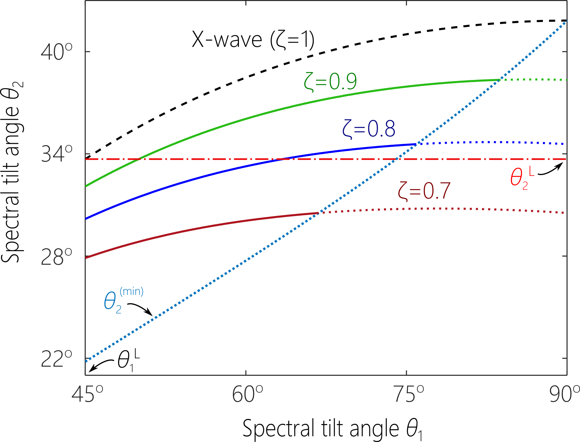
The behavior of this function is quite distinct in the two cases of and . When , decreases monotonically from a maximum value of at to a minimum value of at [Fig. 9(b)]. On the other hand, when , increases monotonically from a minimum value of at , and then becomes unbounded when approaching the critical angle [Fig. 9(c)].
We can now describe the behavior of when tuning the angle of incidence . First, when and the wave packet is subluminal, increases with in a higher-index medium. On the other hand, for superluminal wave packets, decreases with in a higher-index medium. These trends are reversed when . For subluminal wave packets, decreases with in a lower-index medium – approaching zero at the critical angle . On the other hand, for superluminal wave packets, increases with in a lower-index medium, formally reaching infinity at . This unique behavior leads to an intriguing scenario for blind optical synchronization suggested in Ref. Bhaduri et al. (2020), and studied in more detail and realized in paper (III). Additionally, this behavior underlies the recent demonstration of ‘isochronous’ ST wave packets that traverse a planar slab at a fixed group delay at any angle of incidence Allende Motz et al. (2021).
VIII Oblique incidence of X-waves and sideband ST wave packets
The analysis provided above for baseband ST wave packets at oblique incidence does not extend to X-waves or sideband ST wave packets. The reason is that their spatial spectra are not centered at . Instead, the spatial spectrum of the incident wave packet is centered on a non-zero incident angle , where for X-waves and is given by Eq. 19 for sideband ST wave packets. At normal incidence [Fig. 8(a)], this does not effect the symmetry of the transmitted wave packet. However, at oblique incidence [Fig. 8(c)], the two bands of the spatial spectrum (comprising the positive and negative spatial frequencies) impinge on the interface at different angles , and thus also refract at different angles. Consequently, the two bands of the spatial spectrum in the second medium are no longer symmetric with respect to the direction of propagation. This can also be appreciated by noting that the component of the wave vector transverse to the interface (and thus invariant across it) is . Consequently, the transverse and angular wave numbers ( and , respectively) get mixed, thereby fundamentally changing the spatio-temporal spectral structure. This fundamental feature of the refraction of sideband ST wave packets was first recognized in Ref. Donnelly and Power (1997) for the special case of FWMs. The ST wave packet is no longer propagation invariant. Only when the wave packets are extremely close to the luminal limit can this effect be potentially ignored; however, in this case no significant deviation from conventional refraction is observed. As such, we cannot obtain useful laws of refraction for X-waves nor for sideband ST wave packets at oblique incidence.
IX Discussion and conclusion
In Table 1 we summarize the main refraction characteristics for baseband, X-wave, and sideband ST wave packets at normal incidence, including the refractive invariant that allows formulating a law of refraction, the condition for group-velocity invariance, the existence of an anomalous refraction regime, the condition for group-velocity inversion, and whether the subluminal-superluminal barrier can be bridged. Table 2 provides the modifications to the refractive phenomena associated with baseband ST wave packets at oblique incidence with respect to their normal-incidence counterparts. Finally, Table 3 summarizes the refraction of obliquely incident baseband ST wave packets when or .
We have studied ST wave packets transmitted across a planar interface between two dielectrics. Our formulation is based solely on an examination of the spectral support domain on the light-cone. The reflected ST wave packet retains the group velocity of the incident wave packet, with potential changes in the spatio-temporal profile due to the polarization-dependent Fresnel coefficients. Despite potential changes in the complex field amplitudes at each wavelength, and thus changes in the profile (an external DoF), its unique propagation characteristics are nevertheless dictated solely by the underlying spatio-temporal spectral structure (an internal DoF). In the analysis presented here, we have not dealt with the impact of the Fresnel coefficients on the refraction of ST wave packets. The complex field amplitudes along the invariant spectral projection onto the -plane will change upon transmission according to the Fresnel coefficients. At normal incidence, the changes will be symmetric around and independent of wavelength for non-dispersive materials; at oblique incidence, the changes are not symmetric around and are wavelength-dependent even in non-dispersive materials. It is crucial to emphasize that the impact of the Fresnel coefficients is to change the complex field amplitudes and thus the spatio-temporal profile of the wave packet. This change is polarization-dependent, and is more significant at oblique incidence and for large spatial bandwidths. The Fresnel coefficients have no impact on the spectral support domain or the spectral tilt angle. Therefore, the laws of refraction we have formulated here are independent of polarization.
| baseband | X-wave | sideband | |
|---|---|---|---|
| Invariant | |||
| -invariance | No | No | |
| Anomalous | No | No | |
| -inversion | No | No | |
| Bridging gap | No | No | Yes |
| Normal | Oblique | |
|---|---|---|
| Invariant | ||
| -invariance | ||
| Anomalous | ||
| -inversion | ||
| Bridging gap | No | No |
| -invariance | no change | no change |
|---|---|---|
| -inversion | ||
| sublum.- | increases with | decreases with |
| superlum.- | decreases with | increases with |
In conclusion, we have established laws of refraction for the three classes of ST wave packets (baseband, X-waves, and sideband) at normal incidence. These laws govern the change in an internal degree of freedom (the spectral tilt angle) for the transmitted wave packet across a planar interface between two non-dispersive, homogeneous, isotropic dielectrics, and are formulated by identifying a new refractive optical invariant: the spectral curvature. The group velocity of the transmitted wave packet depends not only on the refractive index of the two media, but also on the group velocity of the incident wave packet. Consequently, baseband ST wave packets exhibit fascinating refractive phenomena, such as anomalous refraction, and group-velocity invariance and inversion. At oblique incidence, a law of refraction is formulated for baseband ST wave packets, which shows that the group velocity of the transmitted wave packet depends also on the angle of incidence. The phenomena associated with normal incidence of baseband ST wave packets are retained at oblique incidence after appropriate modifications. Laws of oblique refraction are not formulated for X-waves and sideband ST wave packets, whose structures are fundamentally changed after refraction at oblique incidence. Understanding the refraction of ST wave packets at planar interfaces is crucial for studying their interaction with photonic devices, such as waveguides Zamboni-Rached et al. (2001, 2003); Shiri et al. (2020a); Kibler and Béjot (2021); Béjot and Kibler (2021) and Fabry-Pérot cavities Shabahang et al. (2017); Villinger et al. (2019); Shiri et al. (2020b, c).
In paper (II) and paper (III) of this sequence we provide experimental confirmation of these theoretical predictions regarding baseband ST wave packets.
Funding
U.S. Office of Naval Research (ONR) contract N00014-17-1-2458.
Disclosures. The authors declare no conflicts of interest.
References
- Donnelly and Ziolkowski (1993) R. Donnelly and R. W. Ziolkowski, Proc. R. Soc. Lond. A 440, 541 (1993).
- Longhi (2004) S. Longhi, Opt. Express 12, 935 (2004).
- Saari and Reivelt (2004) P. Saari and K. Reivelt, Phys. Rev. E 69, 036612 (2004).
- Kondakci and Abouraddy (2016) H. E. Kondakci and A. F. Abouraddy, Opt. Express 24, 28659 (2016).
- Parker and Alonso (2016) K. J. Parker and M. A. Alonso, Opt. Express 24, 28669 (2016).
- Kondakci and Abouraddy (2017) H. E. Kondakci and A. F. Abouraddy, Nat. Photon. 11, 733 (2017).
- Kondakci et al. (2019) H. E. Kondakci, M. A. Alonso, and A. F. Abouraddy, Opt. Lett. 44, 2645 (2019).
- Hall et al. (2021) L. A. Hall, M. Yessenov, and A. F. Abouraddy, Opt. Lett. 46, 1672 (2021).
- Reivelt and Saari (2003) K. Reivelt and P. Saari, arxiv:physics/0309079 (2003).
- Kiselev (2007) A. P. Kiselev, Opt. Spectrosc. 102, 603 (2007).
- Hernández-Figueroa et al. (2008) H. E. Hernández-Figueroa, E. Recami, and M. Zamboni-Rached, eds., Localized waves (Wiley-Interscience, 2008).
- Turunen and Friberg (2010) J. Turunen and A. T. Friberg, Prog. Opt. 54, 1 (2010).
- Hernández-Figueroa et al. (2014) H. E. Hernández-Figueroa, E. Recami, and M. Zamboni-Rached, eds., Non-diffracting Waves (Wiley-VCH, 2014).
- Salo and Salomaa (2001) J. Salo and M. M. Salomaa, J. Opt. A 3, 366 (2001).
- Brittingham (1983) J. N. Brittingham, J. Appl. Phys. 54, 1179 (1983).
- Lu and Greenleaf (1992) J.-Y. Lu and J. F. Greenleaf, IEEE Trans. Ultrason. Ferroelec. Freq. Control 39, 19 (1992).
- Saari and Reivelt (1997) P. Saari and K. Reivelt, Phys. Rev. Lett. 79, 4135 (1997).
- Zamboni-Rached et al. (2002) M. Zamboni-Rached, E. Recami, and H. E. Hernández-Figueroa, Eur. Phys. J. D 21, 217 (2002).
- Recami et al. (2003) E. Recami, M. Zamboni-Rached, K. Z. Nóbrega, and C. A. Dartora, IEEE J. Sel. Top. Quantum Electron. 9, 59 (2003).
- Valtna et al. (2007) H. Valtna, K. Reivelt, and P. Saari, Opt. Commun. 278, 1 (2007).
- Zamboni-Rached (2009) M. Zamboni-Rached, Phys. Rev. A 79, 013816 (2009).
- Zamboni-Rached and Recami (2008) M. Zamboni-Rached and E. Recami, Phys. Rev. A 77, 033824 (2008).
- Zapata-Rodríguez and Porras (2006) C. J. Zapata-Rodríguez and M. A. Porras, Opt. Lett. 31, 3532 (2006).
- Porras (2017) M. A. Porras, Opt. Lett. 42, 4679 (2017).
- Efremidis (2017) N. K. Efremidis, Opt. Lett. 42, 5038 (2017).
- Wong and Kaminer (2017a) L. J. Wong and I. Kaminer, ACS Photon. 4, 1131 (2017a).
- Wong and Kaminer (2017b) L. J. Wong and I. Kaminer, ACS Photon. 4, 2257 (2017b).
- Sainte-Marie et al. (2017) A. Sainte-Marie, O. Gobert, and F. Quéré, Optica 4, 1298 (2017).
- Porras (2018) M. A. Porras, Phys. Rev. A 97, 063803 (2018).
- Wong et al. (2020) L. J. Wong, D. N. Christodoulides, and I. Kaminer, Adv. Sci. 7, 1903377 (2020).
- Kibler and Béjot (2021) B. Kibler and P. Béjot, Phys. Rev. Lett. 126, 023902 (2021).
- Shen et al. (2021) Y. Shen, A. Zdagkas, N. Papasimakis, and N. I. Zheludev, Phys. Rev. Res. 3, 013236 (2021).
- Béjot and Kibler (2021) P. Béjot and B. Kibler, arXiv:2103.11620 (2021).
- Froula et al. (2018) D. H. Froula, D. Turnbull, A. S. Davies, T. J. Kessler, D. Haberberger, J. P. Palastro, S.-W. Bahk, I. A. Begishev, R. Boni, S. Bucht, J. Katz, and J. L. Shaw, Nat. Photon. 12, 262 (2018).
- Shaltout et al. (2019) A. M. Shaltout, K. G. Lagoudakis, J. van de Groep, S. J. K. J. V. V. M. Shalaev, and M. L. Brongersma, Science 365, 374 (2019).
- Hancock et al. (2019) S. W. Hancock, S. Zahedpour, A. Goffin, and H. M. Milchberg, Optica 6, 1547 (2019).
- Jolly et al. (2020) S. W. Jolly, O. Gobert, A. Jeandet, and F. Quéré, Opt. Express 28, 4888 (2020).
- Chong et al. (2020) A. Chong, C. Wan, J. Chen, and Q. Zhan, Nat. Photon. 14 (2020).
- Chen et al. (2021) J. Chen, C. Wan, A. Chong, and Q. Zhan, arXiv:2101.09452 (2021).
- Yessenov et al. (2019a) M. Yessenov, B. Bhaduri, H. E. Kondakci, and A. F. Abouraddy, Opt. Photon. News 30, 34 (2019a).
- Kondakci and Abouraddy (2018a) H. E. Kondakci and A. F. Abouraddy, Phys. Rev. Lett. 120, 163901 (2018a).
- Bhaduri et al. (2018) B. Bhaduri, M. Yessenov, and A. F. Abouraddy, Opt. Express 26, 20111 (2018).
- Bhaduri et al. (2019a) B. Bhaduri, M. Yessenov, D. Reyes, J. Pena, M. Meem, S. R. Fairchild, R. Menon, M. C. Richardson, and A. F. Abouraddy, Opt. Lett. 44, 2073 (2019a).
- Yessenov et al. (2019b) M. Yessenov, B. Bhaduri, L. Mach, D. Mardani, H. E. Kondakci, M. A. Alonso, G. A. Atia, and A. F. Abouraddy, Opt. Express 27, 12443 (2019b).
- Kondakci and Abouraddy (2019) H. E. Kondakci and A. F. Abouraddy, Nat. Commun. 10, 929 (2019).
- Yessenov et al. (2020a) M. Yessenov, B. Bhaduri, P. J. Delfyett, and A. F. Abouraddy, Nat. Commun. 11, 5782 (2020a).
- Bhaduri et al. (2019b) B. Bhaduri, M. Yessenov, and A. F. Abouraddy, Optica 6, 139 (2019b).
- Bhaduri et al. (2020) B. Bhaduri, M. Yessenov, and A. F. Abouraddy, Nat. Photon. 14, 416 (2020).
- Shiri et al. (2020a) A. Shiri, M. Yessenov, S. Webster, K. L. Schepler, and A. F. Abouraddy, Nat. Commun. 11, 6273 (2020a).
- Schepler et al. (2020) K. L. Schepler, M. Yessenov, Y. Zhiyenbayev, and A. F. Abouraddy, ACS Photon. 7, 2966 (2020).
- Kondakci and Abouraddy (2018b) H. E. Kondakci and A. F. Abouraddy, Opt. Lett. 43, 3830 (2018b).
- Yessenov et al. (2020b) M. Yessenov, L. A. Hall, S. A. Ponomarenko, and A. F. Abouraddy, Phys. Rev. Lett. 125, 243901 (2020b).
- Yessenov and Abouraddy (2020) M. Yessenov and A. F. Abouraddy, Phys. Rev. Lett. 125, 233901 (2020).
- Yessenov et al. (2021) M. Yessenov, L. A. Hall, and A. F. Abouraddy, arXiv:2102.09443 (2021).
- Yessenov et al. (2019c) M. Yessenov, B. Bhaduri, H. E. Kondakci, and A. F. Abouraddy, Phys. Rev. A 99, 023856 (2019c).
- Shaarawi et al. (2000) A. M. Shaarawi, I. M. Besieris, A. M. Attiya, and E. El-Diwany, J. Acoust. Soc. Am. 107, 70 (2000).
- Attiya et al. (2001) A. M. Attiya, E. El-Diwany, A. M. Shaarawi, and I. M. Besieris, Prog. Electromagn. Res. 30, 191 (2001).
- Shaarawi et al. (2001) A. M. Shaarawi, I. M. Besieris, A. M. Attiya, and E. El-Diwany, Prog. Electromagn. Res. 30, 213 (2001).
- Salem and Baǧcı (2012) M. A. Salem and H. Baǧcı, J. Opt. Soc. Am. A 29, 139 (2012).
- Hillion (1993) P. Hillion, Optik 93, 67 (1993).
- Donnelly and Power (1997) R. Donnelly and D. Power, IEEE Trans. Antennas Propag. 45, 580 (1997).
- Hillion (1998) P. Hillion, J. Opt. 29, 345 (1998).
- Hillion (1999) P. Hillion, J. Opt. A 1, 459 (1999).
- Saleh and Teich (2019) B. E. A. Saleh and M. C. Teich, Fundamentals of Photonics (Wiley, 2019).
- Torres et al. (2010) J. P. Torres, M. Hendrych, and A. Valencia, Adv. Opt. Photon. 2, 319 (2010).
- Fülöp and Hebling (2010) J. A. Fülöp and J. Hebling, in Recent Optical and Photonic Technologies, edited by K. Y. Kim (InTech, 2010).
- Reivelt and Saari (2000) K. Reivelt and P. Saari, J. Opt. Soc. Am. A 17, 1785 (2000).
- Reivelt and Saari (2002) K. Reivelt and P. Saari, Phys. Rev. E 66, 056611 (2002).
- Shaarawi and Besieris (2000) A. M. Shaarawi and I. M. Besieris, J. Phys. A 33, 7255 (2000).
- Saari (2018) P. Saari, Phys. Rev. A 97, 063824 (2018).
- Saari et al. (2019) P. Saari, O. Rebane, and I. Besieris, Phys. Rev. A 100, 013849 (2019).
- Saari and Besieris (2020) P. Saari and I. Besieris, Phys. Rev. A 101, 023812 (2020).
- Besieris et al. (1998) I. Besieris, M. Abdel-Rahman, A. Shaarawi, and A. Chatzipetros, Progr. in Electrom. Res. 19, 1 (1998).
- Bélanger (1984) P. A. Bélanger, J. Opt. Soc. Am. A 1, 723 (1984).
- Bowlan et al. (2009) P. Bowlan, H. Valtna-Lukner, M. Lõhmus, P. Piksarv, P. Saari, and R. Trebino, Opt. Lett. 34, 2276 (2009).
- Bonaretti et al. (2009) F. Bonaretti, D. Faccio, M. Clerici, J. Biegert, and P. Di Trapani, Opt. Express 17, 9804 (2009).
- Kuntz et al. (2009) K. B. Kuntz, B. Braverman, S. H. Youn, M. Lobino, E. M. Pessina, and A. I. Lvovsky, Phys. Rev. A 79, 043802 (2009).
- Allende Motz et al. (2021) A. M. Allende Motz, M. Yessenov, and A. F. Abouraddy, arXiv:2102.10505 (2021).
- Zamboni-Rached et al. (2001) M. Zamboni-Rached, E. Recami, and F. Fontana, Phys. Rev E 64, 066603 (2001).
- Zamboni-Rached et al. (2003) M. Zamboni-Rached, F. Fontana, and E. Recami, Phys. Rev. E 67, 036620 (2003).
- Shabahang et al. (2017) S. Shabahang, H. E. Kondakci, M. L. Villinger, J. D. Perlstein, A. El Halawany, and A. F. Abouraddy, Sci. Rep. 7, 10336 (2017).
- Villinger et al. (2019) M. L. Villinger, A. Shiri, S. Shabahang, A. K. Jahromi, M. B. Nasr, C. Villinger, and A. F. Abouraddy, arXiv:1911.09276 (2019).
- Shiri et al. (2020b) A. Shiri, M. Yessenov, R. Aravindakshan, and A. F. Abouraddy, Opt. Lett. 45, 1774 (2020b).
- Shiri et al. (2020c) A. Shiri, K. L. Schepler, and A. F. Abouraddy, APL Photon. 5, 106107 (2020c).