[1]
[1]This work was partially funded by the regional council of Provence Alpes Côte d’Azur, by the French government through the UCA JEDI ”Investments in the Future” project managed by the National Research Agency (ANR) with the reference number ANR-15-IDEX-01, and was supported by the grant AAP Santé 06 2017-260 DGA-DSH.
[1]Corresponding author:\orcidauthorhttps://orcid.org/0000-0001-6534-6641Wang Zihao
Inner-ear Augmented Metal Artifact Reduction with Simulation-based 3D Generative Adversarial Networks
Abstract
Metal Artifacts creates often difficulties for a high quality visual assessment of post-operative imaging in computed tomography (CT). A vast body of methods have been proposed to tackle this issue, but these methods were designed for regular CT scans and their performance is usually insufficient when imaging tiny implants. In the context of post-operative high-resolution CT imaging, we propose a 3D metal artifact reduction algorithm based on a generative adversarial neural network. It is based on the simulation of physically realistic CT metal artifacts created by cochlea implant electrodes on preoperative images. The generated images serve to train a 3D generative adversarial networks for artifacts reduction. The proposed approach was assessed qualitatively and quantitatively on clinical conventional and cone beam CT of cochlear implant postoperative images. These experiments show that the proposed method outperforms other general metal artifact reduction approaches.
keywords:
Artifact Reduction, Deep Learning, GAN1 Introduction
Computed Tomography (CT) is one of the most widely used imaging techniques in clinical practice. The physical principles of spiral CT lead to the unavoidable creation of artifacts in the reconstructed images in the presence of dense materials, i.e., those composed of atoms with high atomic numbers. Several physical phenomena contribute to the creation of such artifacts, including X-ray beam hardening, X-ray scatter, electronic noise, edge effects and also the geometrical characteristics of metal parts. The artifacts are commonly found in routine clinical postoperative imaging, for instance due to fixation plates in orthopaedics, cochlear electrode implants in otology, contrast agents, etc. These spurious signals in CT images may impair postoperative analysis. For instance, during cochlear implant surgery, an electrode array inserted along the cochlear scala tympani is usually comprised of a metal alloy, for its high electrical conductivity. The existence of metal artifacts in postoperative CT makes the evaluation of the position of the electrodes along the scala difficult. The knowledge of the relative position of the cochlear implant is one of the main determinants for assessing the success of the surgery and leads to appropriate and more personalized patient care.
Metal artifact reduction (MAR) methods aim to decrease the extent of such artifacts (see: 1). Classical non-learning-based MAR algorithms are divided into two groups: corrupted projection recovery and iterative image reconstruction-based methods (Mehranian et al., 2013). In the former case, projections corrupted by the presence of metal absorbing the X-rays are detected and then replaced by predicted or interpolated values, based on prior knowledge (Kalender et al., 1987a). The efficiency of the approach is related to the ability to recover the projected signals in the absence of metal parts (Mehranian et al., 2013). In the case of iterative methods, the missing data in image or projection space is estimated on the basis of statistical principles, possibly including prior knowledge. Aside from Filtered Back Projection (FBP) based methods, (Naranjo et al., 2011) introduced mathematical morphology algorithms for MAR by converting the image to polar coordinates centered on the metal artifact.
1.1 MARGAN approach
Recently, the field of MAR has been revived by the development of deep learning methods that provide supervised mechanisms for extracting relevant image features. A number of 2D Convolutional Neural Network (CNN)-based MAR methods have been proposed that are summarized in Table 1. (Zhang and Yu, 2018) introduced CNNs as prior information in the sinogram (projection) space for the inpainting or sinogram completion task using a simulated dataset in the training stage. However, this method needs either the original CT sinograms (usually unavailable to the typical user) or to project back the input image in order to fill-in the missing traces. This limits its application in our dataset, and the sinogram-based MAR algorithms tend to generate over-smoothed images due to their filtering effect.
Huang et al. (2018) developed a deep learning network, RL-ARCNN, in image space to predict residual images (the difference between the images with and without artifacts) to remove metal artifacts in cervical CT images. The 2D network DestreakNet was proposed in Gjesteby et al. (2018) for streak artifact reduction as a post-processing step in order to recover the details lost after the application of the interpolation-based normalized MAR Meyer (2010) algorithm.
| Processing Domain | Inner Ear MAR | 2D/3D | Dataset Collection |
|
|||
| marBHC | Sinogram | NO | 2D | Non-Learning | YES | ||
| marLI | Sinogram | NO | 2D | Non-Learning | YES | ||
| NMAR | Sinogram | NO | 2D | Non-Learning | YES | ||
| CNN Prior (Zhang and Yu, 2018) | Sinogram | NO | 2D | Simulation (BH) | YES | ||
| RL-ARCNN (Huang et al., 2018) | Image | NO | 2D | Simulation (BH) | YES | ||
| DestreakNet (Gjesteby et al., 2018) | Image | NO | 2D | Simulation (BH) | YES | ||
| DudoNet++ (Lyu et al., 2020) | Sinogram+Image | NO | 2D | Simulation (BH;SC;EN) | NO | ||
| CycleGAN (Nakao and et al., 2020) | Image | NO | 3D | Unsupervised | NO | ||
| cGAN (Wang et al., 2019a) | Image | YES | 2D | Paired Data | YES | ||
| MARGAN (Proposed) | Image | YES | 3D | Simulation (BH;SC;EN) | YES |
(Lyu et al., 2020) proposed Dudonet++ for 2D CT metal artifact reduction. Their approach relies on processing the image with artifacts (henceforth referred to as artifact image) in both sinogram and image spaces in order to restore fine details in the image. Their quantitative evaluation shows that the Dudonet++ is effective for artifact reduction on simulated CT images but it lacks a quantitative evaluation on a clinical dataset. Furthermore, the method uses a beam hardening correction (Verburg and Seco, 2012), which is not always optimal, for instance in the case of Cochlear Implant MAR (see 4).
Recently, generative adversarial networks (GAN) were devised for solving MAR problems instead of CNN classification or regression networks, owing to their ability to generate high quality images. (Wang et al., 2019a) proposed a conditional GAN (cGAN) approach for CT images with cochlear implants (CI), using a collection of paired and registered post- and preoperative cochlear implant volumes to train 2D/3D cGANs for inner ear MAR. A difficulty in this approach is to collect and, most importantly, to register (preoperative) artifact-free and (postoperative) artifact images. This registration problem must be able to cope with the presence of outliers due to the presence of artifacts.
Nakao and et al. also proposed a MAR method based on CycleGANs for artifact reduction in dental filling and neck CT images. The approach is unsupervised and aims to achieve a cross-domain (artifact and artifact-free dataset) style transformation through feature swapping. This approach does not require training on paired datasets, i.e., with and without artifacts, but CycleGAN performance significantly worsens when unpaired data is used (Zhu et al., 2017) for training instead of paired data. This approach was qualitatively compared with the manual corrections available in commercial CT scans and quantitatively assessed on synthetic datasets. While the output of the CycleGANs seems effective, this method may not be useful for the reduction of tiny artifacts like cochlear implants, due to the difficult separability of artifacts in feature space.
1.2 Simulating the presence of metal parts
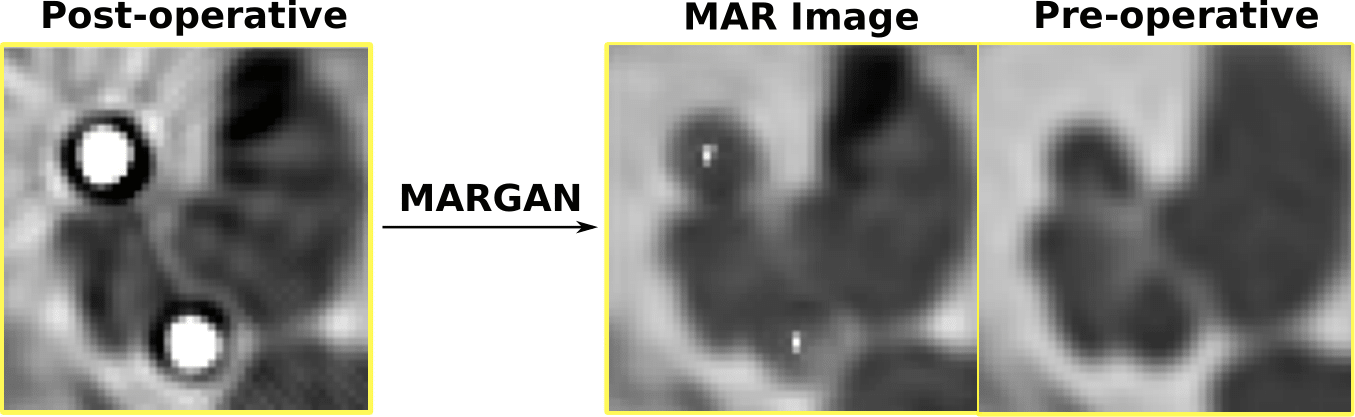
In this paper, we propose a GAN-based MAR method that relies on simulated training data and is suitable for pre- and postoperative images. To the best of our knowledge, our approach is the first MAR algorithm that combines the physical simulation of metal artifacts with 3D GAN networks. While classical GAN-based methods such as (Wang et al., 2019a) rely on the existence of paired images with and without artifacts for training, our approach has several advantages. First, only preoperative images (without artifacts) are required for the training stage, because the generation of the corresponding artifact image is based on physical simulation. This allows a large set of training images (800 images) to be used, without the need for registering the pre- and postoperative images. Second, the nature of artifacts can be easily modulated by controlling the complexity of the artifact simulation model complexity. Third, we introduce the concept of augmented metal artifact reduction by optionally adding landmarks in the corrected image that indicate the central location of metal parts. More precisely, in this paper, we show that for the postoperative cochlear implant CT images, the location of each electrode center can be identified in the corrected image such that ENT (ear, nose and throat) surgeons can assess the quality of the implantation surgery. Compared to CycleGANs (Nakao and et al., 2020), the MARGAN approach allows artifacts to be easily disentangled from the background. This is why we believe this approach is probably more appropriate to attenuate artifacts created by tiny implants. Fourth, MARGAN was evaluated on postoperative, cone beam CT images. Finally, MARGAN was developed as a 3D GAN since metal artifacts usually vary continuously between slices. The contributions of the MARGAN framework is summarized in Tab. 1.
The MARGAN method is based on two main stages (see Fig.3). In the first stage (Fig. 5), given a preoperative image from the training set, one or several images with metal artifacts are generated. This requires a rough segmentation of the structures of interest, the position of metal parts (e.g., electrode arrays) and the simulation of artifacts based on a CT image formation model. Furthermore, the location of the electrode arrays is added to the generated images. In the second stage (Fig. 3), a 3D GAN is trained using preoperative and corresponding simulated artifact images. The GAN loss is improved by adding a term based on Retinex theory to decrease the image blur in generated images. After training, the GAN is applied on a postoperative image without any segmentation or other preprocessing. It results in images with attenuated metal artifacts but also with landmarks corresponding to electrode centers.
The MARGAN method was applied to a set of inner ear CT images to reduce the artifacts created by cochlear implants. Qualitative and quantitative results are provided for 33 paired pre- and postoperative CT images, including a comparison with two classical open source MAR algorithms. Qualitative evaluation of cone beam CT (CBCT) postoperative images is also provided.
This paper extends the initial work published in (Wang et al., 2019b) in several ways. The artifact simulation model is more sophisticated, including scattering effects and electronic noise of the CT system detectors. The algorithm evaluation is more comprehensive, with the addition of paired CT images, CBCT images and a study of the impact of the Retinex loss. The postoperative electrode position is assessed in a few cases with postmortem photographic views of the cochlea.
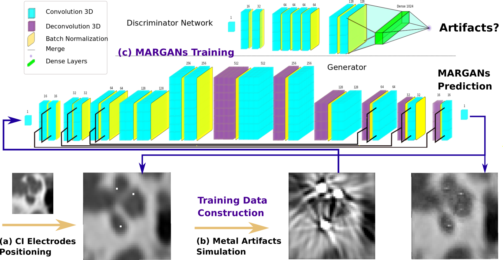
The paper is organized as follows: In section 2, we introduce the CI and CI metal artifact simulation procedures (the gray box in Fig. 3). In section 3, the network implementation is described (the green box in Fig. 3). Results of the MARGAN algorithm are presented in section 4. Sections 5 and 6 discuss the contributions and limitations of the proposed approach.
2 Simulation of metal artifacts in CT images
The simulation of metal artifacts in CT images from artifact-free images entails i) simulating the presence of metal parts in the images as shown in Fig: 2 and ii) simulating the creation of artifacts caused by those metal parts as shown in Fig: 4. The former algorithm is completely dependent on the organ or implant considered, while the latter is far more generic, based on the physics of image formation.
The processing pipeline to generate the training set for the MARGANs is displayed in Fig. 2. In this section, we consider the case of preoperative CT images of the inner ear prior to cochlear implant surgery. The objective is therefore to simulate, in these preoperative images, the addition of metal electrode arrays associated with the implant.
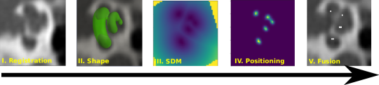
The 3D CT volumes of the inner ear, written as , are first rigidly registered on a template image by a block matching algorithm (Ourselin et al., 2000). The template is a sample CT image that has been manually cropped around the temporal bone. The registration is necessary to cope with the variations of field of view and pose in the input image dataset. A region of interest (ROI) is then cropped to get a cochlear volume suitable for further processing. We then fit a parametric shape model (Demarcy, 2017) to automatically reconstruct the shape of the cochlea (step (II) of Fig: 2). The accuracy required for the registration and segmentation steps is limited.
The signed distance map (Wang and et al., 2020) from the fitted triangular mesh of the parametric shape model is generated as shown in step (III). It is then thresholded (step (IV)) to create a 3D tubular binary mask near the center-line of the scala tympani of the cochlea. This mask corresponds to the probable location of the electrodes after a CI intervention. Finally, in step (V), the voxel values in Hounsfield units (HU) of the mask region are then set to which is the maximum detectable HU of the CI metal artifacts. This creates the image used for training the GAN network.
2.1 Simulation of beam hardening, scattering and electronic noise due to metal parts
The metal parts have large absorption ratios of X-ray energy which is the cause of the visible artifacts in CT images. It impacts the whole image formation process through several physical effects. Our previous work (Wang et al., 2019b) only considered the simulation of the beam hardening effect, inspired by the work of (Zhang and Yu, 2018). In this paper, we improve the realism of the simulated artifacts by also including the X-ray scatter effect through Monte Carlo simulation and the detector electronic noise. The three main physical effects governing the generation of metal artifacts are described below, along with the processing pipeline.
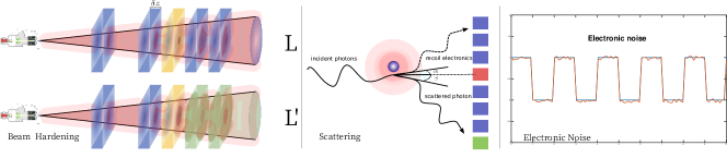
Beam hardening effect
For a monoenergetic X-ray source entering a material of thickness along direction at position , the number of photons is given by the Beer-Lambert law : where is the initial photon number and is the linear attenuation coefficient of the material.
The attenuation coefficient depends on the energy of the input photon , and therefore for a polychromatic X-ray beam having the energy distribution (or spectrum), , the number of photons received by the entire detector surface is then:
| (1) |
where and are the minimum and maximum energies for a fixed tube peak voltage, and is an additive offset that captures X-ray scattering.
Scattering effect
The Compton effect applies to incoming X-ray photons that interact with the free electrons in the traversed materials. This effect results in random changes (scatter) in the directions of the photons, which may still reach the detector plate despite collimator devices. The Compton scatter is enhanced in the presence of metal parts, thus resulting in an offset in the number of photons and leading to a reduction in the image contrast. Computing this additional scatter is very complex as it depends on the projected plane and the material and geometry of the tissue surrounding the metal parts. To this end, we use Monte Carlo simulation to estimate the offset value for different detector positions and orientations. The governing equation for the simulation provides the emission energy of a polychromatic ray deviating by an angle from its initial trajectory :
| (2) |
where is the electron mass and the speed of light. To estimate the scatter effect inside the cochlea on X-ray detectors, we use the (Zubal et al., 1994) head phantom where metal parts are roughly positioned inside the temporal bone. Based on the MCGPU software (Badal and Badano, 2009) performing GPU Monte Carlo simulations of photon transport in voxelized geometry, we simulate thousands of X-ray photon trajectories at different energies, positions and orientations through the head and produce both the scatter-free sinogram and the scatter sinogram offset . The scatter sinogram offset is corrected by a scale factor such that the resulting scatter to primary ratio , falls within the range of 0.1% to 2%, which was experimentally found by Glover et al. (GH, 1982). This is simply done by randomly picking a ratio within 0.1% to 2% and computing
| (3) |
The same ratio is used for simulating all sinograms of the same image to obtain spatially consistent artifacts.
The computation of the scatter offset is dependent on the X-ray energy, position, and orientation but is independent of the input image as it relies on the digital head phantom augmented with metal parts next to the temporal bone. Only the scatter to primary ratio varies between different volumes. This implies that the scatter sinograms can be precomputed, thus alleviating the computational load when generating images with metal artifacts.
Detector Noise
Once photons hit the x-ray detector, the scintillator transforms the deposited energy into visible light, while a photomultiplier translates this light into an electric signal. In this process, some electronic noise is introduced which can be modeled by a zero mean Gaussian distribution (Benson and Man, 2010) with standard deviation : . The signal measured in each sinogram can then be written as: where is the energy deposited as described Eq. 1 and .
Simulation pipeline
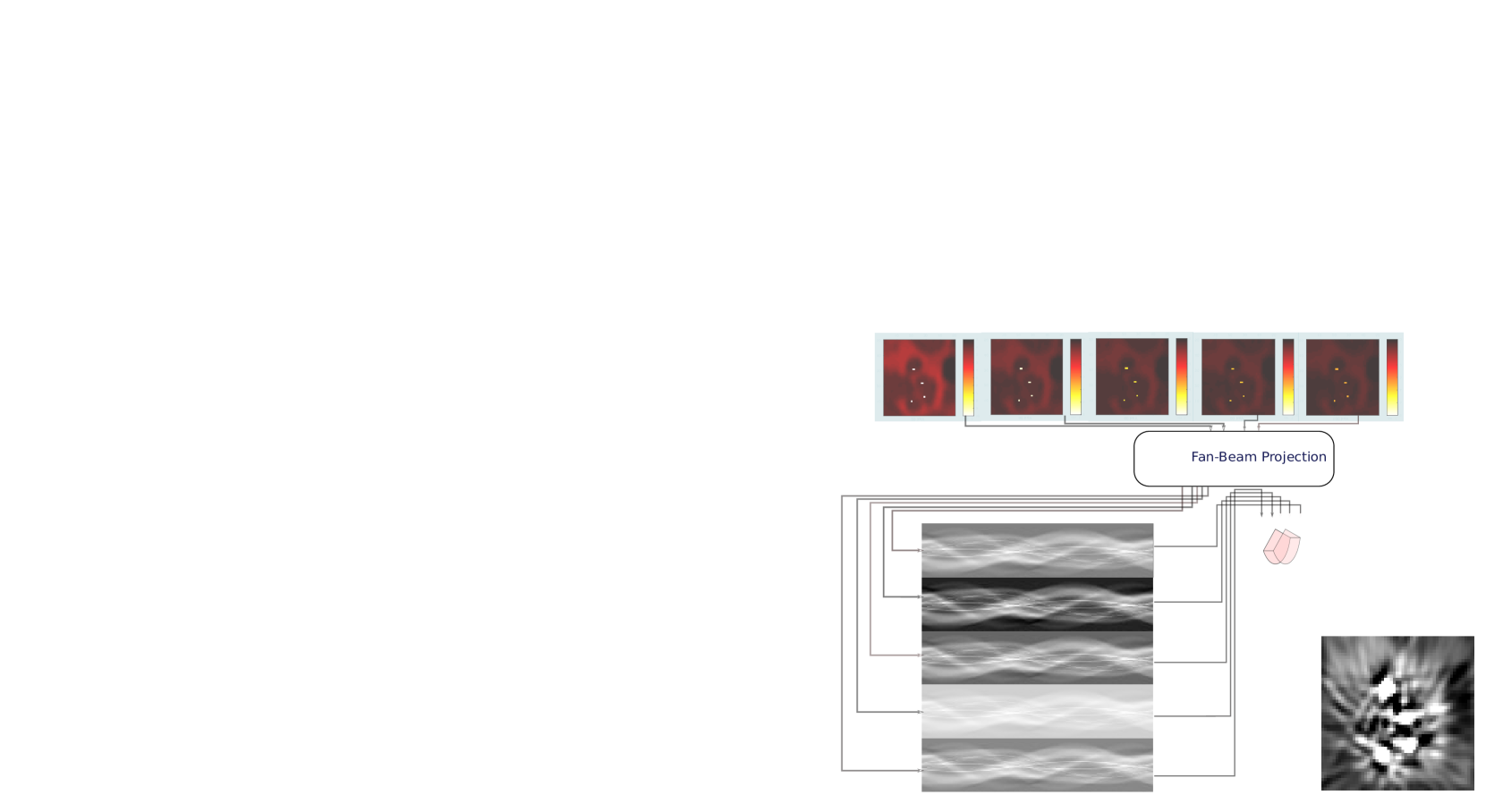
The overall metal artifact simulation pipeline is described in Fig. 5. In the first step, we use an X-ray energy spectrum extracted from a CT manufacturer dedicated site 111https://www.oem-xray-components.siemens.com/x-ray-spectra-simulation for a tungsten anode tube at 140 . The spectrum is sampled at five energies from which attenuation maps are generated. This computation is based on the Hounsfield unit formula and the water absorption coefficients as a function of energy. We then perform fan-beam projection (Step III) of the five attenuation maps to produce sinogram-like images representing absorbed energy on the CT detectors. The scattering and attenuation sinograms are precomputed on a head phantom for various orientations and positions of the source. The projection of the ROI of the head where metal parts have been inserted creates a sine trace on the scattering and attenuation sinograms. This trace is randomly sampled, then normalized as in Eq. 3 to obtain a plausible scatter to primary ratio. It is then added to the electronic noise and to the weighted sum of the five sinograms (Step IV) and a discretization of Eq. 1. Finally, inverse fan-beam projection produces the output image with metallic artifacts (Step V).
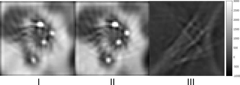
The difference between simulated images with and without scattering noise is shown in Fig. 6 with a subtraction map. We see that scattering and electronic noise can introduce significant new artifacts.
3 GAN-based Metal Artifact Reduction
Given pairs of preoperative and simulated postoperative images, we aim to train a network that generates the former given the latter as a way to reduce metal artifacts. The use of a GAN to tackle the MAR issue is motivated by the successful use of 2D and 3D GANs such as SRGAN (Ledig et al., 2017; Sanchez and Vilaplana, 2018) to solve imaging Super-Resolution (SR) problems.
3.1 Network Overview
In MARGAN, two neural networks are used: the generator network produces the MAR images and the discriminator network indicates whether the input image contains metal artifacts or not. The generator network, , with weights, , aims at modeling the mapping between the image with artifacts, , and the simulated artifact-free image, . We denote by the 3D image created by the generator network, which should be as close as possible to . The discriminator neural network, , tries to detect the presence of artifacts in the generated MAR images, . To train and networks, the sum of discriminator and generator losses is optimized as detailed below.
3.2 Network Architecture
The generator network architecture is similar to U-Net with convolution and deconvolution layers, skip connections and batch normalization layers to improve the training efficiency (see Fig 3). Moreover, unlike (Sanchez and Vilaplana, 2018) which is patch based, the input to the network consists of full 3D images as it is compatible with GPU memory. The number of filters increases gradually from 1 to 512, a number of feature maps that can fit on an 11 Gb video-memory GPU card. The discriminator network follows that of (Sanchez and Vilaplana, 2018) with eight groups of convolution layers and batch normalization layers combined sequentially.
3.3 Loss Functions
Discriminator Loss
The discriminator network, , is trained using output images from the generator network, , and images without any metal artifacts, . Following (Sanchez and Vilaplana, 2018), the discriminator loss enforces the ability of the discriminator network to distinguish the artifact-free images, , from the generated ones, :
Generator Loss
The objective of the generator network is to produce an image, , as close as possible to the target image, . This is why the first loss term is the mean square error (MSE), , to encourage a similarity between generated and target voxels. But using only the MSE loss leads to blurred MAR images with a lack image detail at high frequencies. To avoid this excessive smoothing, we propose a new loss term based on Retinex theory (Land and McCann, 1971). This theory is mostly used to improve images seriously affected by environmental illumination. The Retinex theory assumes that a given image can be considered as the product of environmental brightness (or illumination), , and the object reflectance, . This reflectance map contains high frequency details and is unaffected by the illumination condition, a property referred to as the color constancy phenomenon. The objective of Retinex-based algorithms is to recover the reflectance image from the original one. In single-scale Retinex approaches (Zhang et al., 2011), the environmental brightness is simply a Gaussian blur version of the input image and therefore where is a Gaussian function of standard deviation , and is the convolution operator. This leads us to introduce the following Retinex loss to make its illumination part as close to 1 as possible :
| (4) |
where the expectation is taken over the image domain. This loss definition ensures numerically stable evaluations and enforces salient features in the image that would otherwise be attenuated. Combining it with the adversarial term as in (Sanchez and Vilaplana, 2018), the full optimization target of the generator is:
| (5) |
where is a parameter controlling the influence of the Retinex loss.
| air | water | bones | muscle | titanium | soft tissue | fat | |
| MC-GPU MATERIAL | 1 | 15 | 4 | 2 | 16 | 3 | 6 |
| DENSITY [g/cm3] | 0.001205 | 1.000 | 1.990 | 1.041 | 4.506 | 1.038 | 0.916 |
4 Results
4.1 Dataset
4.1.1 Training data
The cochlea dataset was collected from the Radiology Department of the Nice University Hospital with a GE LightSpeed CT scanner without any metal artifact reduction filters. The preoperative dataset includes 1000 temporal bone images (493 left and 597 right) from 597 patients. The original CT volumes are registered to a sample image by a pyramidal block-matching algorithm in order to spatially normalize all images, then they are resampled with voxel size. They were then cropped to volumes of voxels around the cochlea region. We then simulated on all volumes, the insertion of CI electrodes and the generation of metal artifacts as described in section 2. This created a set of 1000 pairs of images, with and without metal artifacts.
4.1.2 Evaluation Data
The evaluation dataset #1 includes 33 cadaver temporal bone CT images collected from the same site from different bodies. The imaging protocol was the same as for the training dataset but was performed before and after the implantation of CI, thus leading to 33 pre- and postoperative image pairs. The temporal bones were ground by an ENT (ear, nose and throat) surgeon, approximately along a plane perpendicular to the cochlear modiolar axis at the bottom of the scala tympani as shown in Fig. 12. Pictures of the ground bones were acquired in order to visualize the electrode array.
Finally, the second evaluation dataset includes 8 postoperative images that were acquired on a Carestream 9600 cone beam CT (CBCT) following the CI surgery. These images were resampled, registered and cropped following the same processing pipeline as the training set.
| Dataset | Pre-Op | Post-Op | Photography |
| Training | 800 | 0 | 0 |
| Validation | 200 | 0 | 0 |
| Evaluation CT | 33 | 33 | 33 |
| Evaluation CBCT | 0 | 8 | 0 |
4.2 Implementation details
Artifact simulation
A polychromatic X-ray source was simulated with MC-GPU v1.3, a GPU-based Monte Carlo simulator of photon transport in voxelized geometry (Badal and Badano, 2009). To simulate the scatter effects, we simplified the contents of the human head by assuming it consists of air, water, soft tissue, bone, muscle and unalloyed titanium. Cochlear CT voxel values were converted to MC-GPU v1.3 units based on the material mapping in Table 2. The simulation of scatter was performed offline on a GPU parallel computing cluster. The beam hardening maps and the final simulation volumes were computed with Matlab 2017a on a Dell Mobile Workstation with Intel(R) Core(TM) i7-7820HQ @ 2.90GHz CPU.
Neural Networks
The networks were trained with a RMSprop optimizer (Arjovsky et al., 2017) with learning rate for the generator and for the discriminator. The MARGAN was implemented with Tensorflow and the weight of Retinex loss was set to . The batch size and number of epochs were set as and respectively.
4.3 Clinical Evaluation
Qualitative Study
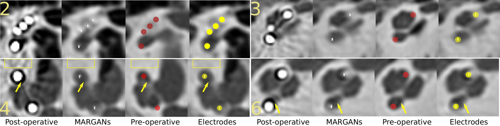
Fig. 9 shows the output of the MARGAN network for four patients on two selected slices together with pre- and postoperative CT images. The streak artifact patterns were largely suppressed by the MARGAN algorithm. As shown inside the yellow boxes, the artifact patterns were significantly reduced compared to postoperative images. The cochlear structures that were slightly distorted by the artifacts (indicated by yellow arrows) were mostly recovered in comparison to the preoperative image slices. Finally, the MARGAN-generated images include by design, high intensity pixels at the potential locations of electrode centers. The yellow circles are clearly positioned in the centers of the electrodes and can help otologists visualize the relative positions of electrodes with respect to the scala tympani.
| Metric | Preoperative | marBHC | marLI | Nmar | MARGAN |
| PSNR | 16.33 | 11.59 | 16.53 | 13.58 | 18.31 |
| RMSE | 0.15 | 0.28 | 0.15 | 0.52 | 0.12 |
| SSIM | 0.58 | 0.56 | 0.55 | 0.52 | 0.64 |
Quantitative Comparison with other MAR algorithms
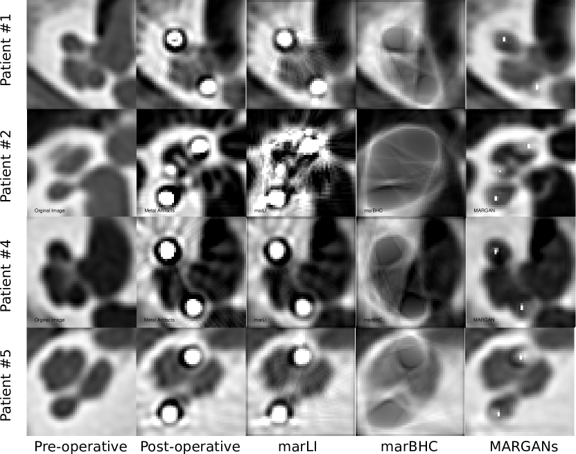
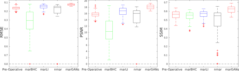
Similar to (Zhang and Yu, 2018), we compared our approach with three open source MAR algorithms: MAR with projection linear interpolated replacement (marLI) (Kalender et al., 1987b), beam hardening correction (marBHC) (Verburg and Seco, 2012) and NMAR (Meyer et al., 2010). The visual assessment of the different MAR algorithms is shown in Fig. 7. The MARGAN approach clearly outperforms the other three MAR methods in its ability to decrease the texture changes of artifacts and to generate an image similar to the preoperative image. All 33 postoperative images were processed by marLI, marBHC, and NMAR. Three global similarity indices, the root mean square error (RMSE), structural similarity index (SSIM) and peak signal to noise ratio (PSNR), were computed between the preoperative images and the MAR images generated by the three comparison methods and our proposed approach. These three indices are reported in Table 4 and capture the preservation of visible structures, the errors and the quality of the reconstructed images. Our method outperforms the other MAR methods for all three metrics (lowest RMSE and largest SSIM and PSNR). In Fig. 8, the same indices were computed for all patient image slices to evaluate the spatial consistency of the reconstruction. Clearly the MARGAN approach exhibits the best performance, with a lower mean value and much lower variance. This can be explained by the fact that it is the only MAR algorithm working directly on 3D images.
4.4 Impacts of methodological contributions
We assess the importance of our methodological contributions by evaluating their impact on the generated MARGAN images when they are removed from the computational pipeline. More precisely, we consider the following two contributions:
-
•
Retinex Loss When zeroing the Retinex scale factor (instead of setting ) during the MARGAN training, only the loss term is used, which is equivalent to minimizing the norm between the generated and ground truth images. We also include in the ablation study the replacement of with the norm involving terms.
- •
| Dataset | PSNR | RMSE | SSIM |
| MARGAN L1 Scatter | 16.67 | 0.1490 | 0.56 |
| MARGAN L2 Scatter | 18.17 | 0.1257 | 0.64 |
| MARGAN L2+Retinex No-Scatter | 18.02 | 0.1277 | 0.63 |
| MARGAN L2+Retinex Scatter | 18.31 | 0.1242 | 0.64 |
In Table 5, we used the three similarity measures PSNR, RMSE and SSIM with respect to the preoperative images as a way to quantify the impact of those contributions.
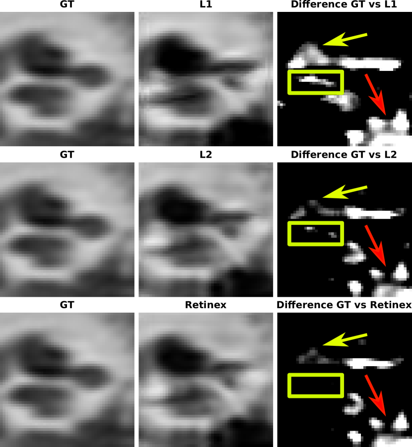
Table 5 shows that both the addition of scatter and electronic noise in the simulation and the addition of the Retinex loss can improve the performance of MAR for all three different metrics. We also see that using a single loss function performs worse than the proposed loss combination approach. A visualization of the image difference output obtained using different training loss functions is shown in Fig. 10 with subtraction maps between different output images and the ground truth image. We see from the yellow and red marks in those subtraction maps the effectiveness of the proposed Retinex loss function in comparison with using pure L1 and L2 losses.
4.5 Out-of-sample Test
To assess the generalization ability of this MARGAN approach, we explore its performance on 8 postoperative CBCT images, noting that the network was trained on CT images.
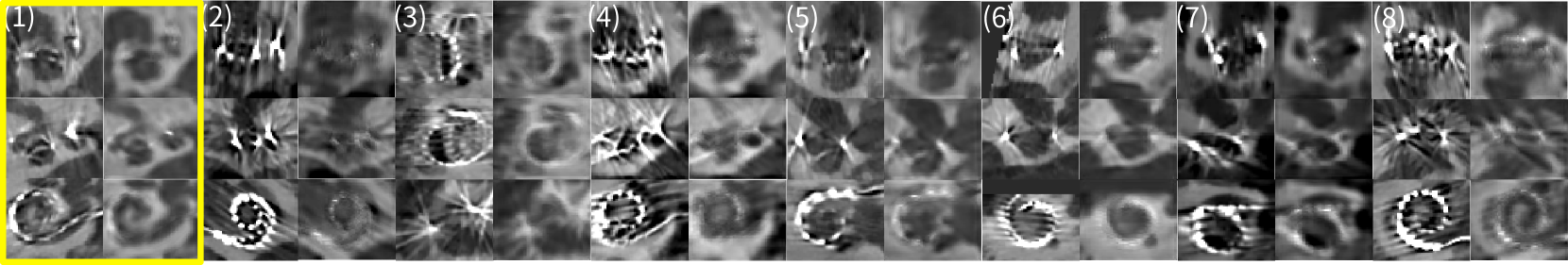
In Fig.11, we see that metal artifacts in CBCT are more extensive and complex than in CT images. Yet, the MARGAN can cope well with those CBCT images and is able to recover most of the cochlear structures.
4.6 CI Electrode Position Prediction
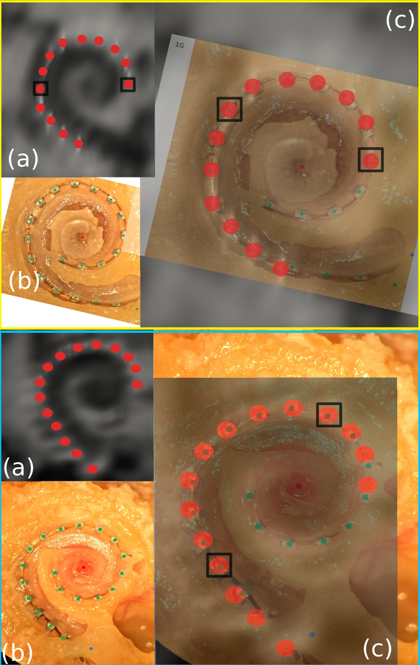
The positioning of CI electrodes in postoperative imaging provides important information for establishing a hearing prognosis (Kós et al., 2005; Todt, 2009) and can be used to improve the cochlear implant programming strategy (Noble et al., 2014). The proposed MARGAN algorithm output images where the electrode centers are outlined by voxels in hypersignal as shown in Fig. 9 and 7. To qualitatively evaluate the positional accuracy of those electrode centers in generated MARGAN images, we use pictures of the cochlea acquired after the dissection and grinding of post-mortem temporal bones following CI surgery ( see Fig. 12(b)). On each generated MARGAN image, a slice having roughly the same position and orientation as the dissection picture has been manually extracted (Fig. 12(a)). Semi-transparent red circles have been manually positioned on the MARGAN slice at high intensity voxels while green dots have been positioned by an otorhinolaryngologist on the electrodes visible in dissection pictures. Furthermore, those two images have been registered with an affine transform estimated after selecting two corresponding electrodes. The two registered images are fused in Fig. 12(c) thus showing the good overlap between green and red circles. This experiment shows that information about the position of the electrodes causing the artifacts was kept after the application of the MARGAN algorithm.
5 DISCUSSION
Our MARGAN approach combines an artifact simulation pipeline with a 3D GAN network that generates augmented preoperative images from postoperative images. The artifact generation algorithm relies on three physical phenomena: beam hardening, scatter and electronic noise. The scatter and noise effects clearly have less impact on the output image compared to beam hardening. Yet, these effects were shown in Table 5 to improve the realism of the output of MARGAN when compared to preoperative images. The simulation pipeline could easily be refined in many ways, for example, using a more hardware-specific energy spectrum, increasing the number of sample energies in the approximation, or including more application-dependent scatter to primary ratios. This approach could also be extended to other imaging systems, such as cone beam CT, dual energy CT or trimodal low-dose X-ray tomography (Zanette and et al., 2012).
The use of 3D GANs allowed us to generate MAR images with spatial coherence across neighboring slices, which is not guaranteed when using 2D slice-by-slice MAR methods. Furthermore, Retinex loss was introduced to improve the sharpness of the MAR images. We show in Tab. 5 that the Retinex loss can improve the performance of the MARGAN with a scale coefficient . However, an inappropriate value can introduce distortions in the MARGAN output. Furthermore, the influence of other hyperparameters in the simulation pipeline on the artifact reduction needs to be further investigated.
The MARGAN approach is both data driven (for the generation of MAR images) and model driven (for the generation of training image pairs). This is in contrast to purely data-driven MAR methods that either rely on pairs of pre- and postoperative images (Jia and et al., 2018) or on non-paired data (Nakao and et al., 2020). The collection of image pairs, with and without artifacts, is mostly restricted to images acquired before and after an intervention such as CI insertion. The use of such pairs makes the 3D GAN fairly effective at removing artifacts in postoperative images. However, the collection of those images may be difficult and an intra-patient image registration is required. The MARGAN pipeline aims at reaching the same efficiency but by replacing the postoperative image with a simulated one. This makes the MARGAN algorithm applicable to a larger set of clinical cases where such image pairs cannot be gathered, for instance in the case of hip, shoulder or knee prostheses. The use of CycleGAN on non-paired images as in (Nakao and et al., 2020) is very appealing, because it avoids both artifact simulation and collection of paired images. However, it has only been tested to remove large artifacts, such as those caused by dental fillings, and with limited quantitative assessment.
Another advantage of the artifact simulation approach in MARGAN is its ability to augment the generated MAR image with voxels indicating the location of the metal part. In the case of CI postoperative images, it enables visualization in the same image of both the cochlea and the implant electrode centers. Note that the augmentation of the MARGAN image is only optional in this framework, because the metal-free image can replace the augmented image as in the loss function of the 3D GAN.
Specifically, in the cochlear metal artifact reduction problem, we see from Fig. 7 and Tab. 4 that almost all the traditional MAR approaches have degradation problems in terms of reconstruction image quality. It was reported in (Meyer et al., 2009) and (Diehn et al., 2017) that sinogram inpainting-based methods can introduce new artifacts. These artifacts can have a severe impact on image quality if the metallic parts and artifacts occupy a large area of space in the image, which is typically the case for the CI electrodes discussed here. However, the risk of quality degradation is not applicable for MARGAN as the image domain-based methods do not need to access the sinogram and the Radon transform.
A limitation of MARGAN lies in the relative complexity of implementing the simulation of metal artifacts in CT images. This is especially true for the scatter effect, which only adds a marginal gain in realism to the generated images. A more thorough study should be performed to evaluate the level of realism required in the simulation pipeline to improve the MARGAN output. Simulating the insertion of metal parts can also be complex as it requires a segmentation algorithm to locate the region of insertion. But this complexity is rewarded by the ability to generate a vast training set accounting for variations in patient anatomy or implant design.
Learning-based MAR methods were shown to outperform traditional sinogram-based MAR approaches in several previous works (Wang et al., 2019a; Zhang and Yu, 2018; Wang et al., 2019b). But by design, the performance of those supervised methods depends on the chosen training set and they are application-specific algorithms. Their integration into a clinical workflow remains to be demonstrated, in particular due to their potential lack of robustness. The successful application of MARGAN on CBCT images unseen during training is an encouraging sign of the generalization ability of MARGAN, though further studies are required.
Finally a limitation common to all MAR methods is the difficulty of evaluating performances quantitatively, due to the lack of ground truth data. The use of paired pre- and postoperative image data enables quantitative comparison through global similarity indices (such as PNSR, RMSE) but is also dependent on the registration quality of the two images. Images with synthetic artifacts created by image processing were also considered in (Nakao and et al., 2020), for instance, but they are computationally intensive to reach sufficient realism. Physical anthropomorphic phantoms are a useful alternative for MAR assessment (Bolstad et al., 2018) but are limited by the number of phantoms considered.
6 CONCLUSION
In this paper, we have introduced a simulation-based 3D GAN to attenuate metal artifacts in CT images. The network is trained on a thousand regular CT images without any artifacts and their corresponding images where metal artifacts have been simulated. We have demonstrated the introduction of scatter and electronic noise effects in addition to beam hardening in an efficient computational pipeline. The complexity of scatter simulation has been alleviated by precomputing the impact of scatter on a generic head phantom where metal parts have been introduced. A Retinex loss was introduced to enhance visible edges in the generated images. The MARGAN approach was evaluated on CT and CBCT images of the inner ear with cochlear implants inserted. The proposed approach provided images close to preoperative images and outperformed open source MAR methods. Furthermore, images generated by MARGAN included the location of the electrode centers, which is useful for assessing the quality of implant surgery.
The trade-off between the complexity of artifact simulation and MARGAN output requires additional study, and we will also investigate the impact of MARGAN images on the automatic registration of pre- and postoperative images.
References
- Arjovsky et al. (2017) Arjovsky, M., Chintala, S., Bottou, L., 2017. Wasserstein gan. arXiv:1701.07875.
- Badal and Badano (2009) Badal, A., Badano, A., 2009. Accelerating monte carlo simulations of photon transport in a voxelized geometry using a massively parallel graphics processing unit. Medical Physics 36, 4878--4880. URL: https://aapm.onlinelibrary.wiley.com/doi/abs/10.1118/1.3231824, doi:10.1118/1.3231824, arXiv:https://aapm.onlinelibrary.wiley.com/doi/pdf/10.1118/1.3231824.
- Benson and Man (2010) Benson, T.M., Man, B.K.B.D., 2010. Synthetic ct noise emulation in the raw data domain. IEEE Nuclear Science Symposium & Medical Imaging Conference , 3169--3171.
- Bolstad et al. (2018) Bolstad, K., Flatabø, S., Aadnevik, D., Dalehaug, I., Vetti, N., 2018. Metal artifact reduction in ct, a phantom study: subjective and objective evaluation of four commercial metal artifact reduction algorithms when used on three different orthopedic metal implants. Acta Radiologica 59, 028418511775127. doi:10.1177/0284185117751278.
- Demarcy (2017) Demarcy, T.t., 2017. Automated analysis of human cochlea shape variability from segmented CT images. Computerized Medical Imaging and Graphics 59, 1 -- 12. URL: https://hal.inria.fr/hal-01528489, doi:10.1016/j.compmedimag.2017.04.002.
- Diehn et al. (2017) Diehn, F.E., Michalak, G.J., DeLone, D.R., Kotsenas, A.L., Lindell, E.P., Campeau, N.G., Halaweish, A.F., McCollough, C.H., Fletcher, J.G., 2017. Ct dental artifact: Comparison of an iterative metal artifact reduction technique with weighted filtered back-projection. Acta radiologica open 6, 2058460117743279. doi:10.1177/2058460117743279.
- GH (1982) GH, G., 1982. Compton scatter effects in ct reconstructions. Med Phys. 9(6), 860-867. doi:doi:10.1118/1.595197.
- Gjesteby et al. (2018) Gjesteby, L., Shan, H., Yang, Q., Xi, Y., Claus, B., Jin, Y., Man, B.D., Wang, G., 2018. Deep neural network for ct metal artifact reduction with a perceptual loss function.
- Huang et al. (2018) Huang, X., Wang, J., Tang, F., Zhong, T., Zhang, Y., 2018. Metal artifact reduction on cervical ct images by deep residual learning. BioMedical Engineering OnLine 17. doi:10.1186/s12938-018-0609-y.
- Jia and et al. (2018) Jia, S., et al., 2018. Automatically segmenting the left atrium from cardiac images using successive 3d u-nets and a contour loss. arXiv:1812.02518.
- Kalender et al. (1987a) Kalender, W.A., Hebel, R., Ebersberger, J., 1987a. Reduction of ct artifacts caused by metallic implants. Radiology 164, 576--577. URL: https://doi.org/10.1148/radiology.164.2.3602406, doi:10.1148/radiology.164.2.3602406, arXiv:https://doi.org/10.1148/radiology.164.2.3602406. pMID: 3602406.
- Kalender et al. (1987b) Kalender, W.A., Hebel, R., Ebersberger, J., 1987b. Reduction of ct artifacts caused by metallic implants. Radiology 164, 576--577. URL: https://doi.org/10.1148/radiology.164.2.3602406, doi:10.1148/radiology.164.2.3602406, arXiv:https://doi.org/10.1148/radiology.164.2.3602406. pMID: 3602406.
- Kós et al. (2005) Kós, M.I., Boëx, C., Sigrist, A., Guyot, J.P., Pelizzone, M., 2005. Measurements of electrode position inside the cochlea for different cochlear implant systems. Acta oto-laryngologica 125, 474--80. doi:10.1080/00016480510039995.
- Land and McCann (1971) Land, E.H., McCann, J.J., 1971. Lightness and retinex theory. J. Opt. Soc. Am. 61, 1--11. URL: http://www.osapublishing.org/abstract.cfm?URI=josa-61-1-1, doi:10.1364/JOSA.61.000001.
- Ledig et al. (2017) Ledig, C., Theis, L., Huszar, F., Caballero, J., Cunningham, A., Acosta, A., Aitken, A., Tejani, A., Totz, J., Wang, Z., Shi, W., 2017. Photo-realistic single image super-resolution using a generative adversarial network, in: Proceedings of the IEEE Conference on Computer Vision and Pattern Recognition (CVPR).
- Lyu et al. (2020) Lyu, Y., Lin, W., Lu, J., Zhou, S.K., 2020. Dudonet++: Encoding mask projection to reduce CT metal artifacts. CoRR abs/2001.00340. URL: http://arxiv.org/abs/2001.00340, arXiv:2001.00340.
- Mehranian et al. (2013) Mehranian, A., Ay, M.R., Rahmim, A., Zaidi, H., 2013. X-ray ct metal artifact reduction using wavelet domain sparse regularization. IEEE Transactions on Medical Imaging 32, 1707--1722.
- Meyer et al. (2009) Meyer, E., Bergner, F., Raupach, R., Flohr, T., Kachelrieb, M., 2009. Normalized metal artifact reduction (nmar) in computed tomography, in: 2009 IEEE Nuclear Science Symposium Conference Record (NSS/MIC), pp. 3251--3255. doi:10.1109/NSSMIC.2009.5401721.
- Meyer et al. (2010) Meyer, E., Raupach, R., Lell, M., Schmidt, B., Kachelrieb, M., 2010. Normalized metal artifact reduction (nmar) in computed tomography. Medical Physics 37, 5482--5493. doi:10.1118/1.3484090.
- Meyer (2010) Meyer, E.t., 2010. Normalized metal artifact reduction (nmar) in computed tomography. Medical Physics 37, 5482--5493. URL: https://aapm.onlinelibrary.wiley.com/doi/abs/10.1118/1.3484090, doi:10.1118/1.3484090, arXiv:https://aapm.onlinelibrary.wiley.com/doi/pdf/10.1118/1.3484090.
- Nakao and et al. (2020) Nakao, M., et al., 2020. Regularized three-dimensional generative adversarial nets for unsupervised metal artifact reduction in head and neck ct images. IEEE Access 8, 109453--109465.
- Naranjo et al. (2011) Naranjo, V., Lloréns, R., Alcañiz, M., López-Mir, F., 2011. Metal artifact reduction in dental ct images using polar mathematical morphology. Computer methods and programs in biomedicine 102, 64—74. URL: https://doi.org/10.1016/j.cmpb.2010.11.009, doi:10.1016/j.cmpb.2010.11.009.
- Noble et al. (2014) Noble, J.H., Gifford, R.H., Hedley-Williams, A.J., Dawant, B.M., Labadie, R.F., 2014. Clinical evaluation of an image-guided cochlear implant programming strategy. Audiol Neurootol 19, 400--411.
- Ourselin et al. (2000) Ourselin, S., Roche, A., Prima, S., Ayache, N., 2000. Block matching: A general framework to improve robustness of rigid registration of medical images, in: MICCAI.
- Sanchez and Vilaplana (2018) Sanchez, I., Vilaplana, V., 2018. Brain mri super-resolution using 3d generative adversarial networks. arXiv:1812.11440.
- Todt (2009) Todt, I.t., 2009. Evaluation of cochlear implant electrode position after a modified round window insertion by means of a 64-multislice ct. Acta oto-laryngologica 129, 966—970. URL: https://doi.org/10.1080/00016480802495388, doi:10.1080/00016480802495388.
- Verburg and Seco (2012) Verburg, J.M., Seco, J., 2012. Ct metal artifact reduction method correcting for beam hardening and missing projections, in: Phys Med Biol.
- Wang et al. (2019a) Wang, J., Noble, J.H., Dawant, B.M., 2019a. Metal artifact reduction for the segmentation of the intra cochlear anatomy in ct images of the ear with 3d-conditional gans. Medical Image Analysis 58, 101553. URL: http://www.sciencedirect.com/science/article/pii/S1361841519300969, doi:https://doi.org/10.1016/j.media.2019.101553.
- Wang and et al. (2020) Wang, Z., et al., 2020. A Deep Learning based Fast Signed Distance Map Generation, in: Medical Imaging with Deep Learning, Montréal, Canada. URL: https://hal.inria.fr/hal-02570026.
- Wang et al. (2019b) Wang, Z., Vandersteen, C., Demarcy, T., Gnansia, D., Raffaelli, C., Guevara, N., Delingette, H., 2019b. Deep learning based metal artifacts reduction in post-operative cochlear implant ct imaging, in: Shen, D., Liu, T., Peters, T.M., Staib, L.H., Essert, C., Zhou, S., Yap, P.T., Khan, A. (Eds.), Medical Image Computing and Computer Assisted Intervention -- MICCAI 2019, Springer International Publishing, Cham. pp. 121--129.
- Zanette and et al. (2012) Zanette, I., et al., 2012. Trimodal low-dose x-ray tomography. Proceedings of the National Academy of Sciences of the United States of America 109, 10199--204. doi:10.1073/pnas.1117861109.
- Zhang et al. (2011) Zhang, R., Huang, Y., Zhen, Z., 2011. A ultrasound liver image enhancement algorithm based on multi-scale retinex theory, in: Bioinformatics and Biomedical Engineering, (iCBBE), pp. 1--3. doi:10.1109/icbbe.2011.5780462.
- Zhang and Yu (2018) Zhang, Y., Yu, H., 2018. Convolutional neural network based metal artifact reduction in x-ray computed tomography. IEEE Transactions on Medical Imaging 37, 1370--1381.
- Zhu et al. (2017) Zhu, J., Park, T., Isola, P., Efros, A.A., 2017. Unpaired image-to-image translation using cycle-consistent adversarial networks, in: 2017 IEEE International Conference on Computer Vision (ICCV), pp. 2242--2251.
- Zubal et al. (1994) Zubal, I.G., Harrell, C.R., Smith, E.O., Rattner, Z., Gindi, G., Hoffer, P.B., 1994. Computerized three-dimensional segmented human anatomy. Medical Physics 21, 299--302. URL: https://aapm.onlinelibrary.wiley.com/doi/abs/10.1118/1.597290, doi:https://doi.org/10.1118/1.597290, arXiv:https://aapm.onlinelibrary.wiley.com/doi/pdf/10.1118/1.597290.