Ultrafast coherent all-optical switching of an antiferromagnet with the inverse Faraday effect
Abstract
We explore the possibility of ultrafast, coherent all-optical magnetization switching in antiferromagnets by studying the action of the inverse Faraday effect in CrPt, an easy-plane antiferromagnet. Using a combination of density functional theory and atomistic spin dynamics simulations, we show how a circularly polarized laser pulse can switch the order parameter of the antiferromagnet within a few hundred femtoseconds. This nonthermal switching takes place on an elliptical path, driven by the staggered magnetic moments induced by the inverse Faraday effect and leading to reliable switching between two perpendicular magnetic states.
Since the first observations of laser-induced subpicosecond demagnetization phenomena [1], ultrafast magnetization dynamics have sparked great interest, motivated both by the promise of fundamental insights into the physics of ultrafast phenomena as well as potential for data storage applications. Purely optically induced magnetization reversal was first observed in the ferrimagnet GdFeCo [2]. The optomagnetic inverse Faraday effect (IFE), in which a magnetic moment is induced by circularly polarized radiation, has been suggested as a possible cause of this effect [2, 3, 4]. However, as was later discovered, thermally induced demagnetization is sufficient to achieve switching [5, 6, 7, 8]. In such a helicity-independent process, the magnetization reversal is facilitated by the vastly different speeds with which the sublattices demagnetize [5]. In ferromagnets, conversely, helicity-dependent switching with the IFE requires a cumulative multishot procedure, like in FePt [9, 10, 11], in which the magnetization is thermally quenched and the IFE sets the direction of remagnetization. These observations have, to varying degree, been ascribed as well to an effect of magnetic circular dichroism on the thermal demagnetization [12, 13].
While the focus has long been on ferri- and ferromagnets [14, 9, 15, 16, 17, 18, 10, 11, 12, 13], more recent research has singled out antiferromagnets as interesting alternatives for spintronics applications [19, 20]. Despite its zero net magnetization, the magnetic state of an antiferromagnet can be detected by utilizing, e.g., the anisotropic magnetoresistance effect [21, 19]. Meanwhile, antiferromagnets come with advantages for ultrafast spintronics applications, like faster spin dynamics and insensitivity to external magnetic fields [19, 22].
In antiferromagnets, two of the switching mechanisms described above can be ruled out as the sublattices demagnetize with the same speed due to their perfect symmetry, and the magnetic circular dichroism is zero. At the same time, the exceptional speed of antiferromagnetic spin dynamics make them more susceptible to ultrashort stimuli like the IFE-induced magnetic moments, which opens up the possibility of a coherent switching process triggered by the IFE, which does not involve the temporary demagnetization of the material.
Here, we assess the plausibility of such a process by calculating the induced magnetic moments ab initio using density functional theory (DFT) and then using these results in atomistic spin dynamics simulations to determine the switching probability. Previous experiments have already shown that the ultrafast IFE can induce coherent magnon excitations in antiferromagnets such as DyFeO3 [23, 24], FeBO3 [25], and NiO [26]. In order to achieve an actual switching process, apart from a sufficiently high intensity and short duration of the laser pulse, it is needed that the employed material exhibits a strong IFE and is not very susceptible to laser-induced heating, as that interferes with the coherent switching process as we will show in the following. It is also advantageous when the material’s anisotropy energy is not so high as to entirely prevent the rotation of the magnetization. For detection through anisotropic magnetoresistance, furthermore, one would optimally choose a material with two perpendicular stable magnetization states.
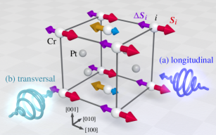
Here, we use CrPt as an example system, an easy-plane antiferromagnet in L10 phase with lattice parameters and [27] (cf. Fig. 1). Only the Cr atoms possess a significant magnetic moment.
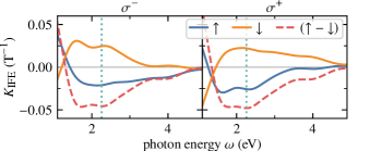
We calculate the magnetic moments induced by the IFE ab initio using the DFT framework developed by Berritta et al. [28]. The induced magnetic moment per spin is given by where is the volume of each spin moment, is the speed of light, is the absorbed intensity of the laser pulse, and is a constant depending on the photon energy , helicity and the local orientation of the Cr moments, denoted by and . The results of our IFE calculations for CrPt in longitudinal geometry are shown in Fig. 2. Interestingly, we find that the induced moments on the Cr sites have a staggered symmetry in the sense that they have opposite sign on the two magnetic sublattices. In analogy to the staggered magnetization of an antiferromagnet, one can define a staggered induced moment as the difference between the moments induced on the different sublattices. This is shown by the dashed line in Fig. 2. The negative sign implies that the induced moments are antiparallel to the local moment on each Cr site. The overall effect of the IFE should be maximal at the point where the magnitude of this staggered induced moment is maximal. This is the case at a photon energy of , where the IFE parameters for the two sublattices are and , for the right-handed () polarization. Due to symmetry breaking, the induced moment is slightly larger on the Cr sublattice that has magnetic moments parallel to the -vector than on the other sublattice with antiparallel moments. With left-handed polarization it would be the other way around. Note that the IFE also induces small moments on the nonmagnetic Pt atoms, but these are not staggered and therefore their effect cancels out [29].
We describe the spin system in the classical Heisenberg model, where each Cr atom is represented by a normalized spin . The Hamiltonian of the system is
| (1) |
The exchange interaction between the atomic spins is described by the coupling energies , calculated ab initio employing DFT [30, 31, 32]. The anisotropy term contains a negative uniaxial anisotropy [27] along the -axis, as well as a weaker, fourth-order anisotropy that leads to four stable orientations of the Néel vector within the easy plane. The coordinate system is chosen such that its axes coincide with the crystallographic axes shown in Fig. 1.
The dynamics of the spin system are computed using the stochastic Landau-Lifshitz-Gilbert (LLG) equation [33, 34, 35, 36]:
| (2) |
Here, is the gyromagnetic ratio, [27] the saturation moment, and the dimensionless Gilbert damping parameter (cf. [29] for details about the choice of and the effect of varying it). is the effective field, given by
| (3) |
with a random thermal noise . The first term in Eq. (2) describes a precession around the effective field and the second term leads to a relaxation of the spins towards the effective field.
We describe the thermal effect of the laser pulse with a simple two-temperature model [37, 38, 29]. To describe the IFE, a spin is added to the spin in all the terms of the Hamiltonian. The exchange term can then be rewritten as
| (4) |
where the first term describes the regular exchange interaction between neighboring spins and the second term describes the interaction of a spin with the induced moments on neighboring lattice sites. The change of the saturation moment in the presence of the induced moments is small enough to be negligible [29].
For the DFT calculations, a stationary state is considered where the light intensity remains at a constant value and the induced magnetic moments are hence directly proportional to the intensity. The exact time dependence of the induced moments in the ultrafast regime, however, is unknown but it is likely not directly proportional to the momentary laser intensity on subpicosecond timescales [39, 4]. We therefore assume, as was done before in similar simulations [11], that the induced moments subside exponentially after the laser pulse on a certain timescale , which was varied between . The following results, unless specified otherwise, use a value of .
All simulations were initialized with all spins aligned parallel to the crystal’s -axis and an initial temperature of . The -vector of the incident laser beam is oriented along the -direction in the longitudinal geometry or along -direction in transversal geometry (cf. Fig. 1). The duration of the laser pulse is always set to (full width at half maximum).
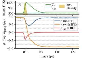
In the longitudinal configuration, magnetic moments will be induced by the IFE that reach between about of the system’s saturation magnetization, depending on the laser intensity. Figure 3 shows the results of an example simulation with an absorbed laser intensity of . The electron system heats up very quickly as the laser pulse arrives, bringing the spin system far above its critical temperature () before cooling down again by dissipating heat to the phonon system. During the high-temperature period the system’s staggered magnetization diminishes markedly but not below approximately half the saturation value. After about half a picosecond, the system has reached thermal equilibrium again. To show the influence of the IFE, we carried out simulations both with and without the induced magnetic moments. Without the IFE, the magnetization of the sublattices is temporarily reduced but then remagnetizes without changing its direction. With the IFE, the induced magnetic moments exert a torque moving the spins towards the opposite direction. This reversal process takes only about . The initial torque is only produced if the induced magnetic moments are not exactly collinear to the magnetization, but laser excitation and thermal fluctuations at room temperature lead to sufficient deviations from the ground state for a significant torque to be exerted.
This example shows that ultrafast switching via the IFE is possible in CrPt. However, the underlying process is not deterministic and the switching probability depends on many parameters, like the laser intensity, the absorption coefficient, the angle of incidence, the shape of the laser pulse, and the way the temporal evolution of the induced magnetic moments is modeled. In order to determine the probability of a switching process to occur for a certain set of parameters, each simulation was repeated several hundred times for different realizations of the thermal noise.
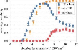
The statistical results for switching in longitudinal geometry are presented in Fig. 4. To discern the dissipative from the non-dissipative effects, simulations were also performed without the induced magnetic moments (only laser-induced heating) and without the heating (magnetic moments are induced, but the temperature remains at ). Without the IFE, the switching probability remains close to zero and only increases for higher laser intensities, where the spin system becomes strongly demagnetized, such that the resulting orientation is randomized. Without the heating, the switching probability still goes up to and does not decrease for higher intensities. This shows that the switching process we observe here is caused by the IFE and cannot be attributed to dissipative effects. The switching in CrPt is thus notably distinct from that of ferrimagnetic GdFeCo, which is a thermal process that requires sufficient heat to nearly demagnetize the sublattice moments before the magnetization builds up again [5, 7]. Conversely, in CrPt a larger laser heating works against the coherent switching action of the IFE (Fig. 4).
We have performed similar simulations for an L10 FePt spin lattice, using the spin model developed by Mryasov et al. [40], so we can compare the behavior of antiferromagnetic CrPt to that of ferromagnetic FePt. The situation in FePt is different in as much as it is an easy-axis ferromagnet with a very strong anisotropy. This allows only for switching in FePt, along the easy anisotropy axis. Our simulations of the switching process in FePt confirm previous findings [11], according to which no deterministic single-pulse switching occurs in FePt. The IFE can only slightly increase the switching probability. Hence, in order to change the magnetization of an ensemble of FePt nanograins, multiple laser pulses need to be applied [9].
One factor that makes the switching process easier in CrPt is that the anisotropy barrier is much lower than in FePt. In FePt, the laser intensity needs to be high enough to completely demagnetize the spin lattice before it can then remagnetize in the opposite direction.
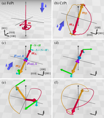
The trajectory of the magnetization vector during this process is illustrated in Fig. 5(a). The time it takes the spin system to fully demagnetize is close to a picosecond. After that time, the magnetic moments induced by the laser pulse are no longer present. Then, the magnetization slowly builds up again, leading to a linear reversal path (cf. [41]), similar to GdFeCo [3]. Consequently, we find that the IFE can only have a marginal effect on the remagnetization direction, consistent with experiments [9, 11].
We further find that when the CrPt model is artificially made ferrimagnetic by varying the magnetic moment of one sublattice with respect to the other, the switching probability diminishes rapidly (data on this can be found in [29]). In antiferromagnetic CrPt, however, the Néel vector can simply rotate within the easy plane without the material losing its magnetic order [cf. Fig. 5(b)]. The whole rotation only takes a few hundred femtoseconds, not much longer than the laser pulse itself.
The main reason for this difference in speed is the exchange-enhanced dynamics of antiferromagnets. The interplay of damping and precession torque that leads to this effect is visualized schematically in Fig. 5(c–f). The precession term dominates the dynamics on short timescales because the damping term is usually much smaller as it scales with the damping parameter . At the beginning of the switching process [panel (c)] the induced magnetic moments cause the precession term of the LLG, which is perpendicular to the effective field, to drive the sublattice magnetizations out of the easy plane. But because the moments are staggered, the direction of precession is opposite on the two sublattices, such that the precessional torque pulls the spins on both sublattices in the same direction, leading to a small canting between the sublattice magnetizations. This canting then leads to an effective field produced by the exchange interaction between the sublattices, which is much stronger than that caused by the induced moments. This effective field is oriented along the anisotropy axis, such that the following precession around it leads to an in-plane rotation of the spins [see panel (d), which shows the moment of maximum laser intensity]. Panel (e) shows the situation shortly after the laser pulse. By that time, the induced moments are no longer present in the system. But because the sublattices are still canted, the switching motion continues driven by the precessional torque. This effect is known as inertial switching [42, 43]. Because of the comparatively low damping torque, the canting subsides only slowly. Finally, panel (f) shows the complete switching path.
If slightly lower laser intensities are used, the induced moments will be weaker and the Néel vector more likely to rotate only instead of .
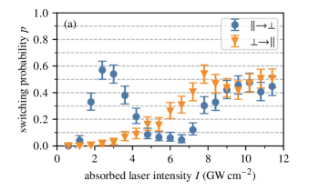
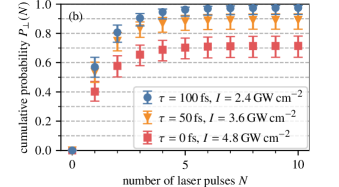
Figure 6(a) shows the computed probability of achieving switching that way for various laser intensities. This probability does not get much higher than but, as Fig. 6(a) also shows, once the system is in a perpendicular state, the probability of switching back into a state parallel to the -vector of the incident light is very low because only negligible magnetic moments are induced by the IFE with transversal incidence.
So if several consecutive laser pulses are used, the amount of switched systems in an ensemble will increase with every pulse. If describes the probability of switching from a parallel to a perpendicular state and describes the probability of switching back (with being the probability of remaining in the perpendicular state after a pulse), then the switching probability after infinitely many pulses is given by . The probability of being in a perpendicular state after pulses can be expressed as . The results of this calculation are shown in Fig. 6(b), for different values of the decay time . We find that with an experimentally realistic laser intensity it should be possible to reach a very high switching probability after only a few pulses.
In summary, our spin dynamics simulations show how all-optical magnetization switching can be induced by the IFE in an easy-plane antiferromagnet. The IFE is found to induce staggered moments and to have a much more pronounced effect in the antiferromagnetic spin lattice than in ferro- and ferrimagnetic systems. It is the particular properties of antiferromagnets that allow for exchange-enhanced, inertial switching on an elliptical path. This process is triggered by staggered magnetic moments induced by the IFE and takes place within a few hundred femtoseconds and, for some parameter values, with close to probability. Furthermore, our results suggest that a sequence of multiple laser pulses can be used for controllable switching between two perpendicular magnetization states. The latter result is most important for an experimental validation of this switching process since switching is easily detectable via anisotropic magnetoresistance measurements.
Acknowledgements.
We thank J. Hurst for valuable discussions. This work has been supported by the German Research Foundation (DFG) under Grant No. 290/5-1 and through CRC/TRR 227, the Swedish Research Council (VR), the K. and A. Wallenberg Foundation (Grant No. 2015.0060), the Horizon2020 Framework Programme of the European Commission under FET-Open Grants No. 737093 (FemtoTerabyte) and 863155 (s-Nebula), and the Czech Science Foundation (Grant No. 19-13659S). Part of the calculations were enabled by resources provided by the Swedish National Infrastructure for Computing (SNIC) at NSC Linköping partially funded by the Swedish Research Council through grant agreement No. 2018-05973, and by the Ministry of Education, Youth and Sports of the Czech Republic through the e-INFRA CZ (ID:90140).References
- Beaurepaire et al. [1996] E. Beaurepaire, J.-C. Merle, A. Daunois, and J.-Y. Bigot, Ultrafast spin dynamics in ferromagnetic nickel, Phys. Rev. Lett. 76, 4250 (1996).
- Stanciu et al. [2007] C. D. Stanciu, F. Hansteen, A. V. Kimel, A. Kirilyuk, A. Tsukamoto, A. Itoh, and T. Rasing, All-optical magnetic recording with circularly polarized light, Phys. Rev. Lett. 99, 047601 (2007).
- Vahaplar et al. [2009] K. Vahaplar, A. M. Kalashnikova, A. V. Kimel, D. Hinzke, U. Nowak, R. Chantrell, A. Tsukamoto, A. Itoh, A. Kirilyuk, and T. Rasing, Ultrafast path for optical magnetization reversal via a strongly nonequilibrium state, Phys. Rev. Lett. 103, 117201 (2009).
- Vahaplar et al. [2012] K. Vahaplar, A. M. Kalashnikova, A. V. Kimel, S. Gerlach, D. Hinzke, U. Nowak, R. Chantrell, A. Tsukamoto, A. Itoh, A. Kirilyuk, and T. Rasing, All-optical magnetization reversal by circularly polarized laser pulses: Experiment and multiscale modeling, Phys. Rev. B 85, 104402 (2012).
- Radu et al. [2011] I. Radu, K. Vahaplar, C. Stamm, T. Kachel, N. Pontius, H. A. Dürr, T. A. Ostler, J. Barker, R. F. L. Evans, R. W. Chantrell, A. Tsukamoto, A. Itoh, A. Kirilyuk, T. Rasing, and A. V. Kimel, Transient ferromagnetic-like state mediating ultrafast reversal of antiferromagnetically coupled spins, Nature 472, 205 (2011).
- Mentink et al. [2012] J. H. Mentink, J. Hellsvik, D. V. Afanasiev, B. A. Ivanov, A. Kirilyuk, A. V. Kimel, O. Eriksson, M. I. Katsnelson, and T. Rasing, Ultrafast spin dynamics in multisublattice magnets, Phys. Rev. Lett. 108, 057202 (2012).
- Ostler et al. [2012] T. A. Ostler, J. Barker, R. F. L. Evans, R. W. Chantrell, U. Atxitia, O. Chubykalo-Fesenko, S. El Moussaoui, L. Le Guyader, E. Mengotti, L. J. Heyderman, F. Nolting, A. Tsukamoto, A. Itoh, D. Afanasiev, B. A. Ivanov, A. M. Kalashnikova, K. Vahaplar, J. Mentink, A. Kirilyuk, T. Rasing, and A. V. Kimel, Ultrafast heating as a sufficient stimulus for magnetization reversal in a ferrimagnet, Nat. Commun. 3, 666 (2012).
- Wienholdt et al. [2013] S. Wienholdt, D. Hinzke, K. Carva, P. M. Oppeneer, and U. Nowak, Orbital-resolved spin model for thermal magnetization switching in rare-earth-based ferrimagnets, Phys. Rev. B 88, 020406 (2013).
- Lambert et al. [2014] C.-H. Lambert, S. Mangin, B. S. D. C. S. Varaprasad, Y. K. Takahashi, M. Hehn, M. Cinchetti, G. Malinowski, K. Hono, Y. Fainman, M. Aeschlimann, and E. E. Fullerton, All-optical control of ferromagnetic thin films and nanostructures, Science 345, 1337 (2014).
- El Hadri et al. [2017] M. S. El Hadri, M. Hehn, G. Malinowski, and S. Mangin, Materials and devices for all-optical helicity-dependent switching, J. Phys. D: Appl. Phys. 50, 133002 (2017).
- John et al. [2017] R. John, M. Berritta, D. Hinzke, C. Müller, T. Santos, H. Ulrichs, P. Nieves, J. Walowski, R. Mondal, O. Chubykalo-Fesenko, J. McCord, P. M. Oppeneer, U. Nowak, and M. Münzenberg, Magnetisation switching of FePt nanoparticle recording medium by femtosecond laser pulses, Sci. Rep. 7, 4114 (2017).
- Khorsand et al. [2012] A. R. Khorsand, M. Savoini, A. Kirilyuk, A. V. Kimel, A. Tsukamoto, A. Itoh, and T. Rasing, Role of magnetic circular dichroism in all-optical magnetic recording, Phys. Rev. Lett. 108, 127205 (2012).
- Ellis et al. [2016] M. O. A. Ellis, E. E. Fullerton, and R. W. Chantrell, All-optical switching in granular ferromagnets caused by magnetic circular dichroism, Sci. Rep. 6, 30522 (2016).
- Eimüller et al. [2001] T. Eimüller, P. Fischer, G. Schütz, M. Scholz, G. Bayreuther, P. Guttmann, G. Schmahl, and M. Köhler, Magnetization reversal of a multilayered FeGd dot array imaged by transmission x-ray microscopy, J. Appl. Phys. 89, 7162 (2001).
- Mangin et al. [2014] S. Mangin, M. Gottwald, C.-H. Lambert, D. Steil, V. Uhlíř, L. Pang, M. Hehn, S. Alebrand, M. Cinchetti, G. Malinowski, Y. Fainman, M. Aeschlimann, and E. E. Fullerton, Engineered materials for all-optical helicity-dependent magnetic switching, Nat. Mater. 13, 286 (2014).
- Ellis and Chantrell [2015] M. O. A. Ellis and R. W. Chantrell, Switching times of nanoscale FePt: Finite size effects on the linear reversal mechanism, Appl. Phys. Lett. 106, 162407 (2015).
- Nieves and Chubykalo-Fesenko [2016] P. Nieves and O. Chubykalo-Fesenko, Modeling of ultrafast heat- and field-assisted magnetization dynamics in FePt, Phys. Rev. Appl. 5, 014006 (2016).
- Gerlach et al. [2017] S. Gerlach, L. Oroszlany, D. Hinzke, S. Sievering, S. Wienholdt, L. Szunyogh, and U. Nowak, Modeling ultrafast all-optical switching in synthetic ferrimagnets, Phys. Rev. B 95, 224435 (2017).
- Jungwirth et al. [2016] T. Jungwirth, X. Marti, P. Wadley, and J. Wunderlich, Antiferromagnetic spintronics, Nat. Nanotechnol. 11, 231 (2016).
- Jungwirth et al. [2018] T. Jungwirth, J. Sinova, A. Manchon, X. Marti, J. Wunderlich, and C. Felser, The multiple directions of antiferromagnetic spintronics, Nat. Phys. 14, 200 (2018).
- Fina et al. [2014] I. Fina, X. Marti, D. Yi, J. Liu, J. H. Chu, C. Rayan-Serrao, S. Suresha, A. B. Shick, J. Železný, T. Jungwirth, J. Fontcuberta, and R. Ramesh, Anisotropic magnetoresistance in an antiferromagnetic semiconductor, Nat. Commun. 5, 4671 (2014).
- Roy et al. [2016] P. E. Roy, R. M. Otxoa, and J. Wunderlich, Robust picosecond writing of a layered antiferromagnet by staggered spin-orbit fields, Phys. Rev. B 94, 014439 (2016).
- Kimel et al. [2005] A. V. Kimel, A. Kirilyuk, P. A. Usachev, R. V. Pisarev, A. M. Balbashov, and T. Rasing, Ultrafast non-thermal control of magnetization by instantaneous photomagnetic pulses, Nature 435, 655 (2005).
- Perroni and Liebsch [2006] C. A. Perroni and A. Liebsch, Magnetization dynamics in dysprosium orthoferrites via the inverse faraday effect, Phys. Rev. B 74, 134430 (2006).
- Kalashnikova et al. [2007] A. M. Kalashnikova, A. V. Kimel, R. V. Pisarev, V. N. Gridnev, A. Kirilyuk, and T. Rasing, Impulsive generation of coherent magnons by linearly polarized light in the easy-plane antiferromagnet , Phys. Rev. Lett. 99, 167205 (2007).
- Satoh et al. [2010] T. Satoh, S.-J. Cho, R. Iida, T. Shimura, K. Kuroda, H. Ueda, Y. Ueda, B. A. Ivanov, F. Nori, and M. Fiebig, Spin oscillations in antiferromagnetic nio triggered by circularly polarized light, Phys. Rev. Lett. 105, 077402 (2010).
- Zhang et al. [2012] R. Zhang, R. Skomski, X. Li, Z. Li, P. Manchanda, A. Kashyap, R. D. Kirby, S.-H. Liou, and D. J. Sellmyer, L10 CrPt phase formation and magnetic properties, J. Appl. Phys. 111, 07D720 (2012).
- Berritta et al. [2016] M. Berritta, R. Mondal, K. Carva, and P. M. Oppeneer, Ab Initio theory of coherent laser-induced magnetization in metals, Phys. Rev. Lett. 117, 137203 (2016).
- [29] See Supplemental Material, which includes Refs. [44, 45], for details about the spin model and additional data on the effect of varying simulation parameters.
- Liechtenstein et al. [1984] A. I. Liechtenstein, M. I. Katsnelson, and V. A. Gubanov, Exchange interactions and spin-wave stiffness in ferromagnetic metals, J. Phys. F: Met. Phys. 14, L125 (1984).
- Turek et al. [1997] I. Turek, V. Drchal, J. Kudrnovský, M. Šob, and P. Weinberger, Electronic Structure of Disordered Alloys, Surfaces and Interfaces (Kluwer, 1997).
- Turek et al. [2006] I. Turek, J. Kudrnovský, V. Drchal, and P. Bruno, Exchange interactions, spin waves, and transition temperatures in itinerant magnets, Philos. Mag. 86, 1713 (2006).
- Landau and Lifshitz [1935] L. Landau and E. Lifshitz, On the theory of the dispersion of magnetic permeability in ferromagnetic bodies, Phys. Zeitsch. der Sow. 8, 153 (1935).
- Gilbert [2004] T. L. Gilbert, A phenomenological theory of damping in ferromagnetic materials, IEEE T. Magn. 40, 3443 (2004).
- Brown [1963] W. F. Brown, Jr., Thermal fluctuations of a single-domain particle, Phys. Rev. 130, 1677 (1963).
- Nowak [2007] U. Nowak, Classical spin models, in Handbook of Magnetism and Advanced Magnetic Materials, edited by H. Kronmüller and S. Parkin (John Wiley & Sons, 2007) Chap. Micromagnetism, pp. 858–876.
- Kaganov et al. [1957] M. I. Kaganov, I. M. Lifshitz, and L. V. Tanatarov, Relaxation between electrons and the crystalline lattice, Sov. Phys. JETP 4, 173 (1957).
- Anisimov et al. [1974] S. I. Anisimov, B. L. Kapeliovich, and T. L. Perel’man, Electron emission from metal surfaces exposed to ultrashort laser pulses, Sov. Phys. JETP 39, 375 (1974).
- Popova et al. [2011] D. Popova, A. Bringer, and S. Blügel, Theory of the inverse Faraday effect in view of ultrafast magnetization experiments, Phys. Rev. B 84, 214421 (2011).
- Mryasov et al. [2005] O. N. Mryasov, U. Nowak, K. Y. Guslienko, and R. W. Chantrell, Temperature-dependent magnetic properties of FePt: Effective spin Hamiltonian model, Europhys. Lett. 69, 805 (2005).
- Kazantseva et al. [2009] N. Kazantseva, D. Hinzke, R. W. Chantrell, and U. Nowak, Linear and elliptical magnetization reversal close to the Curie temperature, EPL 86, 27006 (2009).
- Kimel et al. [2009] A. V. Kimel, B. A. Ivanov, R. V. Pisarev, P. A. Usachev, A. Kirilyuk, and T. Rasing, Inertia-driven spin switching in antiferromagnets, Nat. Phys. 5, 727 (2009).
- Wienholdt et al. [2012] S. Wienholdt, D. Hinzke, and U. Nowak, THz switching of antiferromagnets and ferrimagnets, Phys. Rev. Lett. 108, 247207 (2012).
- Papusoi et al. [2018] C. Papusoi, T. Le, C. C. H. Lo, C. Kaiser, M. Desai, and R. Acharya, Measurements of Gilbert damping parameter for CoPt-based and CoFe-based films for magnetic recording applications, J. Phys. D 51, 325002 (2018).
- Strungaru et al. [2020] M. Strungaru, S. Ruta, R. F. L. Evans, and R. W. Chantrell, Model of magnetic damping and anisotropy at elevated temperatures: Application to granular FePt films, Phys. Rev. Appl. 14, 014077 (2020).