The nylon balloon for xenon loaded liquid scintillator in KamLAND-Zen 800 neutrinoless double-beta decay search experiment
Abstract
The KamLAND-Zen 800 experiment is searching for the neutrinoless double-beta decay of 136Xe by using 136Xe-loaded liquid scintillator. The liquid scintillator is enclosed inside a balloon made of thin, transparent, low-radioactivity film that we call Inner Balloon (IB). The IB, apart from guaranteeing the liquid containment, also allows to minimize the background from cosmogenic muon-spallation products and 8B solar neutrinos. Indeed these events could contribute to the total counts in the region of interest around the Q-value of the double-beta decay of 136Xe. In this paper, we present an overview of the IB and describe the various steps of its commissioning minimizing the radioactive contaminations, from the material selection, to the fabrication of the balloon and its installation inside the KamLAND detector. Finally, we show the impact of the IB on the KamLAND background as measured by the KamLAND detector itself.
1 Introduction
Neutrinoless double-beta () decay searches are direct probes of Majorana neutrinos and lepton number violation [1]. Many Grand Unified Theories predict a Majorana nature for the neutrino, and connect the neutrino’s small mass to grand unification scale physics through the see-saw mechanism [2, 3, 4]. In addition, the matter-antimatter asymmetry of the universe could be explained by some leptogenesis models, which also predict Majorana neutrinos [5]. Regardless of theoretical motivations, the detection of decay would signify lepton number violation, and would mark the first observation of asymmetric matter creation in the laboratory. For these reasons, searches for decay are being vigorously pursued around the world.
KamLAND-Zen is searching for decay of the nucleus 136Xe. Experimentally, decay searches require a large nuclei mass and a low-background environment given the very long half-lives expected for decay (>1026 yr) and the Q-values of a few MeV. In KamLAND-Zen, the energy region surrounding the Q-value of the 136Xe decay, 2.458 MeV [6], is subject to environmental background from contamination present in the existing KamLAND detector material, including 238U-series and 232Th-series decays. To minimize such contamination, we developed a low-background nylon balloon to contain xenon-loaded liquid scintillator (Xe-LS) for the KamLAND-Zen experiment. The first phase, KamLAND-Zen 400 using a clean nylon balloon and enriched xenon up to 383 kg started in 2011 and obtained a lower limit for the decay half-life of yr at 90 % C.L. [7]. The next phase of KamLAND-Zen, KamLAND-Zen 800 with a cleaner balloon which was made with improved methods and new techniques started in 2018. In this paper, we describe the design of the balloon (Section 3), the component materials (Section 4), the production methods and clean environment procedures (Section 5), the installation of the balloon into the KamLAND detector (Section 6), and finally the contamination analysis of the balloon (Section 7).
2 Detector
2.1 KamLAND detector
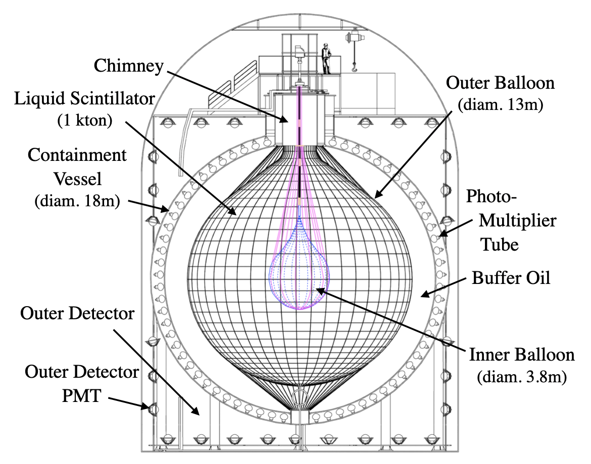
KamLAND (Kamioka Liquid scintillator Anti-Neutrino Detector) is a neutrino detector based on 1,000 tons of purified liquid-scintillator (LS) in a low background environment with 2,700 m.w.e. rock overburden in the Kamioka mine in Japan [8]. The collaboration has published measurements of reactor anti-neutrinos [9], geological anti-neutrinos [10, 11], and solar neutrinos [12, 13]. Figure 1 shows a schematic view of the KamLAND detector. It consists of a spherical stainless-steel tank, photomultiplier tubes (PMTs), buffer oil, and a 13-m-diameter balloon (outer balloon, OB) filled with LS (KamLAND LS). The KamLAND-Zen experiment introduces a second smaller balloon (inner balloon, IB) of LS loaded with 136Xe-enriched xenon at the center of the detector.
The outer balloon is made of five-layered nylon/EVOH film and is 135 m thick. The buffer oil between the outer balloon and the stainless-steel vessel shields the LS against external radiation. Isotropic emission photons from ionizing radiation in the LS are detected by an array of 1,325 17-inch PMTs and 554 20-inch PMTs covering 34% of the inner surface of the detector. The vertex position and energy of the physics events are reconstructed from the timing correlation and charge of the hit PMTs, accounting for the transparency of the LS, the balloon film and buffer oil. The achieved resolution is 12 cm/ for the vertex reconstruction and 6.4%/ for the energy [9]. The ultra-low background (10-17 g/g for uranium and thorium [13]) and huge volume (1,200 m3) of the LS make KamLAND one of the most sensitive LS detector environments for decay searches.
2.2 KamLAND-Zen 800
KamLAND-Zen (KamLAND Zero neutrino double beta decay search) [14] is an experiment searching for the decay of 136Xe inside KamLAND, where the IB filled with Xe-LS is suspended at the center of the detector. KamLAND-Zen 800 uses 745 kg xenon with a 91% isotopic abundance of 136Xe. Xenon is soluble in LS up to 3.1% by weight at atmospheric pressure. It can be extracted from LS by vacuum degassing and nitrogen bubbling. Backgrounds from radioactive elements in the Xe-LS are reduced by purifying the LS [13] and xenon [15] separately. The Xe-LS is transparent at its peak emission wavelength of 385 nm.
The Q-value of 136Xe decay is 2.458 MeV. Several backgrounds exist in this energy region: environmental radiation from 238U-series, pileup events from 232Th-series in LS, cosmogenic muon spallation products of carbon (10C, etc.) and xenon, and solar 8B neutrinos. The 10C and pileup events can be rejected analytically: the 10C is vetoed through the triple coincidence of muon, neutron, and beta/gamma-ray events from 10C decay with a tagging efficiency estimated at about 90% [16]. The pileup occurs in close time coincidence within a single event window (200 ns) and is also a possible background, but it can be rejected using long-time sequential decays as long as rates from other backgrounds such as 210Po are low [17]. To reduce backgrounds proportional to the LS volume, such as spallation products and solar 8B neutrinos, it is advantageous to maximally load the nuclei in the smaller volume of the inner balloon rather than using the full LS volume of KamLAND at a lower loading percentage. The balloon itself introduces radioactive backgrounds proportional to its total weight, therefore low-radioactivity materials with minimal mass are required.
Due to its spherical shape, the access space into the detector is limited to a 50-cm-diameter opening at the top of KamLAND. The IB is therefore installed and suspended from the chimney region at the top of the detector. To meet these mechanical constraints as well as to achieve the background requirements, we selected a balloon vessel made of thin, transparent, and foldable low-background polymeric film for the decay search in KamLAND-Zen.
3 Inner Balloon
3.1 Inner balloon design
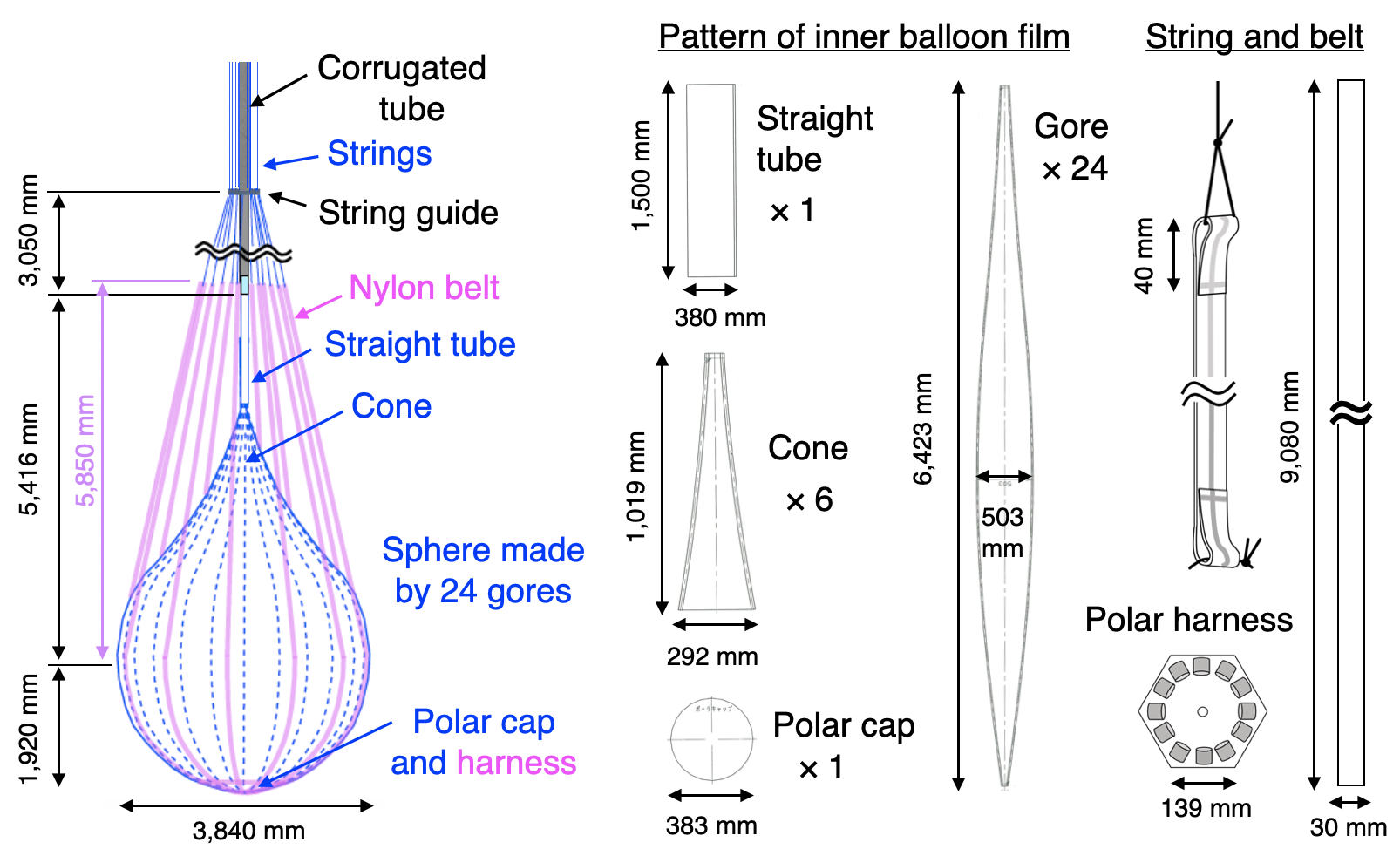
The IB is designed in a teardrop shape with smooth curves to avoid stress concentration, as shown in Figure 2. We designed the IB with a volume of 31.5m3 determined by the amount of xenon of 750 kg and the solubility to LS of 3.0 wt%, which leads to the balloon radius to be 1,920 mm. The IB consists of a main sphere formed from 24 gores, a lower polar cap, an upper cone formed from six film segments, and a 1,500-mm-long straight tube. The 25 m-thick nylon film sections are connected by the heat-welding method described in Section 5. The sections are overlaid by 15 mm for welding at the seams.
The IB is supported by twelve 30-mm-wide nylon belts made of the same material as the IB itself. The connection of these belts to the polar harness at the bottom of the balloon is described in Section 5.8. The belts are connected to twelve 0.4-mm-diameter strings (Fujinoline Corporation) made of Vectran (Kuraray Corporation) in the region of the corrugated tube, well above the IB body. The radioactive contamination of these strings is not sufficiently small for them to be employed near the IB. The strings enable easier handling of the balloon during installation. The top ends of the strings are connected to a rotary ratchet that can adjust their lengths in 1.5-mm steps. The ratchet is suspended by a load cell (SRM200-50N, Controls Japan Company) to monitor the total weight of the IB. A string guide made of polyether ether ketone (PEEK) leads the strings into the chimney area of KamLAND. To prevent expansion or contraction due to head pressure we use a corrugated tube for the connection between the straight tube at the top of the IB and the KamLAND chimney (Section 3.3).
3.2 Xenon-loaded liquid scintillator
To avoid damage to the IB, the density of Xe-LS is tuned to very closely match the KamLAND LS in the outer balloon. The KamLAND LS density is 0.77728 kg/L at 15 ∘C. It consists of 20% pseudocumene (1,2,4-trimethylbenzene, 0.8797 kg/L), 80% dodecane (CH3(CH2)10CH3, 0.7526 kg/L), and 1.36 g/L of PPO (2,5-diphenyloxazole). The density increase caused by the xenon dissolved in the LS could be counterbalanced by reducing the pseudocumene/dodecane fraction, but this would reduce the light yield, which depends on the amount of pseudocumene. We therefore replace the dodecane with decane (CH3(CH2)8CH3, 0.7339 kg/L) to maximize the pseudocumene fraction in xenon-loaded LS. The decane-based LS contains 18% pseudocumene, 82% decane, and 2.38 g/L of PPO. The density of the Xe-LS can be controlled with an accuracy of 0.02% by tuning the pseudocumene/decane fraction. The actual density of the Xe-LS is slightly heavier than the outer KamLAND LS. It is controlled within 0.1% to the KamLAND LS at all times, from installation through data acquisition, to avoid damage to the IB caused by deformation if this was to float in the KamLAND LS. The final density difference between the outer KamLAND LS and inner Xe-LS is about 0.02%. The isotopic abundance of 136Xe is 90.9%, and the remaining components are 124Xe–134Xe. The total amount of 136Xe in the IB is 677 kg.
3.3 Corrugated tube
The uppermost straight section of the inner vessel consists of a hard nylon tube. This design avoids contraction or expansion at the surface of LS due to the head pressure between the outer KamLAND LS and the inner Xe-LS. This tube has to be bent during the IB installation, so we used a corrugated nylon tube (CYLG-95B, PMA Company). The 238U contamination of the corrugated tube was measured by ICP-MS at NTT-AT Co. to be 910-12 g/g after washing, a level acceptable for use in KamLAND. However, this contamination level is about five times larger than that of the IB film. As the tube thickness is 1 mm, 40 times thicker than the film, the total 238U contamination is 200 times that of the film, per unit surface area. To avoid -rays from the corrugated tube introducing backgrounds into the Xe-LS in the spherical area of the IB, the lower straight section is made of IB film for the first 1.5 m above the body of the IB.
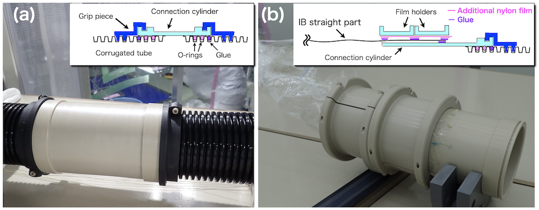
The total length of corrugated tube is about 6 m and the diameter is about 10 cm. It is separated into three sections to allow cleaning in the clean-room and to allow it to be kept straight during transportation. The three sections are connected with a custom-made cylinder made of PEEK as commercial connection cylinders were found not to be compatible with our LS. This connection uses fluoro-rubber O-rings, which can be used in LS. A grip piece is used to secure the connection between the cylinder and the tube and prevent it from falling out. Figure 3(a) shows the connection between the cylinder and corrugated tubes. The connection between the corrugated tube and the straight film tube of the IB is also via a PEEK cylinder, as shown in Figure 3(b). The connection between the film tube and the rest of the IB is described in Section 5.6.
4 Film Selection
We selected a custom-made nylon film for the IB because no commercial film satisfied our requirements on the chemical compatibility and radioactive contamination. These are described in the present section, together with the measured values.
4.1 Chemical compatibility and handling
Only a few kinds of film materials are compatible with a pseudocumene-based LS: ethylene tetrafluoroethylene (ETFE), nylon, and ethylene-vinylalcohol copolymer (EVOH). The outer balloon was fabricated using nylon and EVOH. However, the multi-layered film was made with glue which has radioactive impurities. We therefore had to select a single-layer film. We assessed chemical compatibility by checking for a decrease in the transparency of LS after soaking the films. For nylon and EVOH films, the transparency of the liquid samples after the film soaking was consistent within measurement error to a reference sample of the same scintillator.
EVOH has high gas impermeability. However, an EVOH film was easily torn during the production of an 80-cm-diameter test balloon. ETFE showed creep under tension, so an ETFE vessel could not stably maintain its shape. A nylon film was therefore the only candidate for the IB film.
4.2 Radioactive contamination
The 214Bi in the 238U-series is one of the primary backgrounds for our decay search (Figure 4(a)). The target level of 238U in the balloon film is 10-12 g/g for a film thickness of 25 m assuming the secular equilibrium. This level was set at (10%) of the estimated event rate from 10C that survives a 10C tagging veto. Commercial nylon films have high impurity levels (10-9 g/g at 238U). However, cleaner films can be specially made without “filler”. The filler is inorganic lubricant used to avoid static electricity and to prevent the film sticking to itself. We used custom-made Nylon-6 film produced by Toyobo Company from pellets produced by Ube Industries. The 238U level in this nylon film was measured with ICP-MS to be 210-12 g/g, sufficient for our requirements. This contamination level is consistent with that of KamLAND-Zen 400 film, and the secular equilibrium between 238U and 214Bi was confirmed by 214Po() energy spectrum shape analysis in KamLAND-Zen 400 [18].
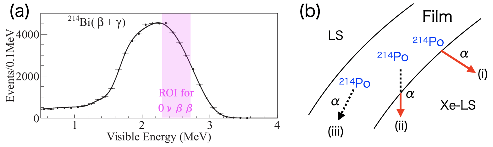
We can tag 214Bi decays in the film by detecting the -ray from the subsequent decay of 214Po ( = 237 sec) under certain conditions, namely when the particle leaves the film and deposits energy in the LS, producing a visible energy level above threshold (Figure 4(b)). A 25 m-thick film realizes 50% 214Po detection in KamLAND. Although this 214Bi rejection power is limited, this detection can be used for background estimation. Thus a 25 m thickness was preferred.
4.3 Transparency
A low-transparency film decreases the detector energy resolution. This leads to an increased background level by shifting the signal from two neutrino double-beta () decays into the decay signal region. Transparency corrections could also result in a significant difference in visible energy scales inside and outside the IB, resulting in an energy distortion for events occurring near or traversing the balloon boundary. To avoid these problems, the transparency should be greater than 95% at the effective wavelength (370–400 nm). The nylon film transparency in LS was measured to be more than 99%. This level preserves the visible energy balance between energy deposited inside and outside the IB.
4.4 Mechanical strength
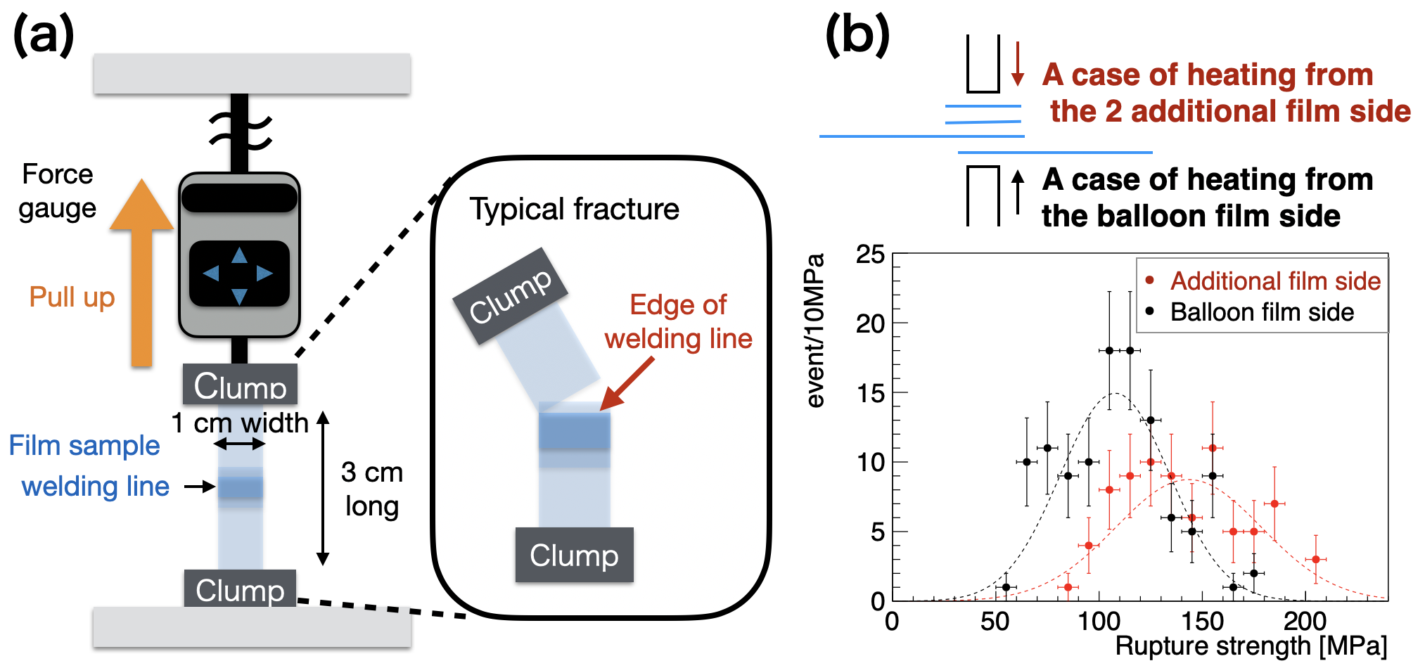
For an IB radius of about 2 m and a density difference between the LS inside and outside the balloon less than 0.1%, we estimate a maximum stress of 4 MPa to the balloon film. Considering the deformation of the balloon shape, we set a design requirement of 40 MPa strength, allowing a safety factor of 10. The breaking strength of our film was measured with a force gauge (ZTA-500N, Imada Company) to be about 180 MPa for the direction of film extrusion and about 320 MPa in the perpendicular direction. The strength of welded film is described in Section 5.5.
4.5 Tightness to xenon
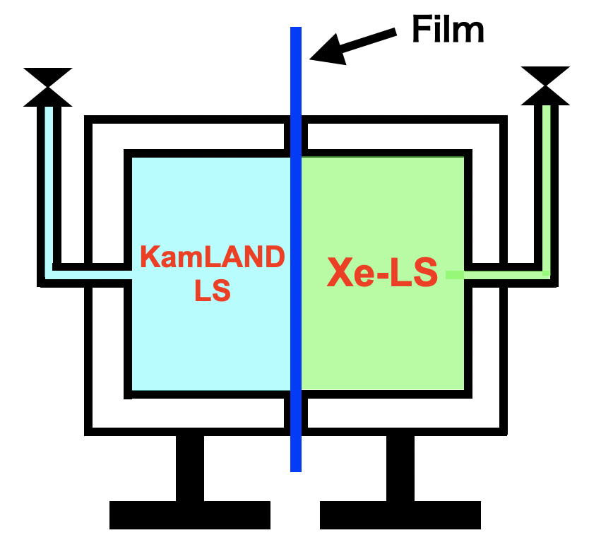
We checked the tightness to xenon of the nylon film using a separated stainless-steel box as shown in Figure 5. We filled one side of the box with Xe-LS and the other side with KamLAND LS. We allowed several months to test the penetration of xenon from the Xe-LS to the KamLAND LS through the nylon film. The level of xenon in the KamLAND LS was then measured by gas chromatography (GC-4000 Plus, GL Sciences Company). We did not measure any xenon in this sample of KamLAND LS. The estimated upper limit on the xenon leak rate from the Xe-LS through the IB film is 1.9 kg over 5 years. This result is an acceptable level for the xenon loss and its impact is negligible in the systematic error for 0 decay search analysis.
5 Inner Balloon Fabrication
5.1 Clean-room
The IB was fabricated in Class 1 (ISO 14644-1) clean-rooms (super clean-room, SCR) at the Micro System Integration Center at Tohoku University in Sendai, Japan, about 600 km from the Kamioka detector site. Outside air is passed through multiple HEPA filters into the building. The entire ceiling area of each SCR is comprised of ULPA filters to maintain a Class 1 environment where the clean air is flowing down from the ceiling to the grating floor. The size of each room is 3.8 m in height, 14.0 m in-depth, and 3.6 m in width. We used two SCRs, a preparation room and a fabrication room for the IB. To avoid the contamination of the fabrication room, the preparation room was used for multiple purposes including welding tests, operational checks of devices, tool cleaning, and changing from normal clean-room suits to SCR suits. The ceiling, walls, floor, and all inner surfaces in the SCR were wiped with ultra-pure water and clean wiping cloths before using the room to avoid particles originating from these surfaces to accumulate on the IB film by static electricity. We used SFIDA and MAX-3003 (MCC Company) wiping cloths in the SCRs. Both cloths were packed at Class-1000 clean-room (FED-STD-209, consistent with Class 5 in ISO 14644-1), so we washed each cloth with ultra-pure water multiple times (3–5 times). We analyzed the particle flow from human workers, wiping cloths, and other sources and monitored the air flow routes on the work table using particle visualization systems with a green laser. Based on these analyses, we established a procedure requiring that all materials, including the cloths, had to be washed with ultra-pure water, and that SCR wear had to be sent for cleaning after each use.
The custom-made nylon film we used for the IB reaches a static electric potential of about +3 kV because it was fabricated without filler. It is therefore susceptible to contamination by dust attraction and accumulation. In general, humidity levels above 65% prevent static electricity, but the SCR humidity is normally less than 65% between autumn and spring in Japan. We therefore set up a mist generation system just before the ULPA filter sending clean air to the SCR. The AirAKI® (H.IKEUCHI Company) uses ultra-pure water and compressed air to generate 10-m water mist at up to 144 L/hour to maintain 65% humidity in the room. We also introduced two devices to avoid static electricity. A Keyence SJ-F5500 neutralization system was used on all films while handling the film. Another Keyence SJ-H neutralization bar was used when we took nylon films from the roll.
5.2 Tool cleaning
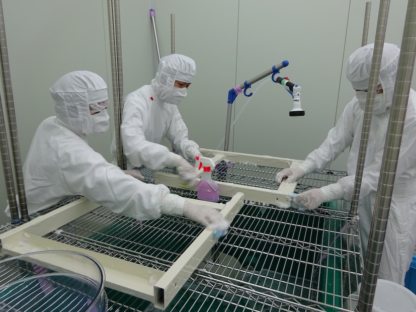
We washed all the tools, devices, and other materials used in the SCR by detergent and ultra-pure water, ethanol, isopropyl alcohol, or ethanol with ultra-sonic cleaning. The ethanol was mainly used to remove machine oil from the metal tools. Isopropyl alcohol was used to clean the metal tools that touched the IB and to remove the guide lines marked with pen on the nylon film. The detergent used was Magiclean (Kao Company); this was employed on almost all tools and devices as shown in Figure 6. An average of one to two tonnes of ultra-pure water were used per day during the washing.
5.3 Corrugated-tube cleaning
The surface of the corrugated tube, which presents grooves at regular intervals of around 1 cm, was contaminated by large and small particles and by stains of machine and other oils. The outside of the tube was cleaned with a brush and detergent, by wiping with ethanol using a cloth, and by ultra-sonic cleaning with ultra-pure water. The inside was cleaned with a brush and detergent, by flushing it with ethanol, and by ultra-sonic cleaning with ultra-pure water. An abridged version of this cleaning procedure had already been applied to the same corrugated tube for the preparation of the KamLAND-Zen 400 experiment: this was shown to yield sufficient cleanliness following in-situ measurements in the KamLAND detector.
5.4 Film washing, cover setting and cutting
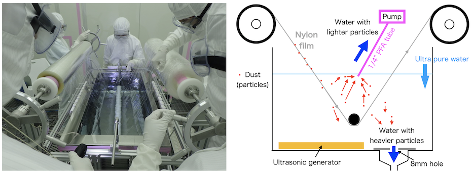
The first step of IB fabrication was cleaning the nylon film to remove surface contamination. We used ultra-sonic cleaning in ultra-pure water in a stainless-steel tub as shown in Figure 7. The film speed was set to about 40 m/hour, a balance between the need to drain the water off the nylon by gravity and minimizing the risk of water sticking to the film due to surface tension. Light particles were removed from the water by pumping the water at the surface level. Heavier particles were removed through three 8-mm diameter draining holes at the bottom of the cleaning tub. We applied this cleaning procedure twice, thus reducing the 238U level from 910-12 g/g to 210-12 g/g, as measured by ICP-MS at NTT-AT Co.
We set cover films over both sides of the IB film during the several-month period required of balloon fabrication to avoid dust accumulation due to static electricity. The cover films were made of the same clean film as the IB and adhered to the IB film by static electricity. When we cut the film into the balloon patterns we cut all three layers simultaneously. During the welding, we turned back the edges of the cover films, and after the balloon sections had been joined, the cover-film edges were unfolded to cover and protect the welding lines.
Nylon film was cut into 32 rectangles with dimensions 7.5 m 1 m to make the 24 gore sections, 6 cone sections, the polar cap and polar harness, and one straight tube section, as shown in Figure 2. After cutting we made alignment marks on the film for welding position checks. These marks were made with a Microperm 03 pen (Sakura Color Products Company). The 238U level of the ink was measured by ICP-MS at NTT-AT Co. to be 1.210-10 g/g, an acceptable value considering the tiny amount of remnant ink on the IB.
5.5 Welding
Nylon films are typically joined with glue. The Borexino experiment [19] used resorcinol to glue sections of 125-m nylon film together. However, the glues we tested made many holes in 25-m nylon film, and we could not find suitable gluing procedures to avoid this problem. Working with DAIZO Corporation, we instead developed a method to join nylon films by heat welding. The melting point of Nylon-6 is about 225 ∘C. The components of our film are 30% crystallized nylon and 70% amorphous nylon [20]. As a result, low-temperature welding at less than 225 ∘C is possible by molecular motion. However, in our welding tests we found that high-temperature welds were stronger than low-temperature welds. We therefore tuned the welding parameters based on high-temperature welding.
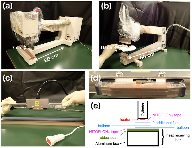
The primary welding machine was made by Fuji impulse Company (Figure 8(a)). It generated impulse heating over a 5 mm 310 mm area and could apply heat between 180 to 250 ∘C for 0.5 to 10 seconds. NITOFLON® tape (Polytetrafluoroethylene base tape, Nitto Denko Corporation) was applied over the heater surfaces to prevent the melted film from sticking to the device. We found that a two-layer welding with the primary welding machine produced many holes in the weld. To avoid this problem, we added two additional layers of film along the seams, for a total of four layers with a combined thickness of 100 m. A schematic of the final welding configuration is shown in Figure 8(e). The additional films melt under heating and filled in holes in the IB film. They also avoided overheating the IB film. After testing a range of parameters, we established a welding procedure using 225 ∘C heating for 3.5 seconds. The pressing pressure was released when the temperature reached 80 ∘C. The strength of the welded seams was measured with a force gauge as shown in Figure 9(a). Figure 9(b) shows the film strength after welding. This figure indicates that heating through the added films produces a stronger weld than heating the IB film directly. During balloon production, all seams were welded by applying heat through the added films.
Some of the welds required to form the IB presented special challenges. To make the final weld between the gores forming the main body of the sphere, the upper heater of the welder had to be outside the volume of the balloon while the heat-receiving bar had to be inside, a topological impossibility with the primary welding machine. In several regions where weld lines converged we needed shorter welds than the 31-cm lengths of the primary welding machine, namely in the areas near the bottom pole, at the junction between the gores and the upper cone, and at the connection between the upper cone at the straight tube. We worked with Creative Design and Engineering (Laporte, Colorado, USA) to develop a secondary welding machine (Figure 8(b)) to address these issues. The secondary machine features a 10-cm heater and a lower heat-receiving bar designed to allow the second layer of film to pass under the bar. The best welding parameters for the secondary machine were welding at 225 ∘C for 10.0 seconds. Welds made with the secondary machine had strength greater than 160 MPa, slightly stronger than the primary machine.
The welding parameters of the primary and secondary machines were tuned to provide the nominal strength. However, welding still periodically resulted in holes along the weld lines. The number of holes in the welds was variable and depended on additional factors that we could not completely control, including the room temperature, the humidity, and the condition of the NITOFLON® tape between the IB film and the heater. We therefore developed a methods to patch these holes, as is described in Section 5.7.
Most of the welding lines were made in 30-cm increments using the primary welding machine. However, since the heat-receiving bar opposite the heating element in this machine could not be detached, the final weld line in the main body of the sphere was kept open, as were other welds in areas where weld lines converged. These final welds were made in smaller increments with the secondary welding machine (Figure 8(b)), with a few particularly difficult areas done using a hand welding machine (Figure 8(c)). Both these smaller machines allow the heat-receiving bar to be positioned inside the balloon volume.
5.6 Connection cylinder
The IB and the upper corrugated tube are connected by a plastic cylinder made of PEEK, by using PEEK film holders, additional nylon film, and glue, as shown in Figure 3(b). The outer circumference of the connection cylinder and the inner surface of the top of the straight-tube section of the IB are a tight fit. Once connected, they can support 20 kg. However, to reduce the risk of slippage of the IB, we clamped the IB film with outer film holders made of PEEK. We applied glue to fill any small gaps that might allow gas or liquid to leak. The glue we used was “Adcoat” a mixture of 91% AD-76P-1 with 9% CAT-10L (Toyo-Morton Company, 238U 110-11 g/g measured with ICP-MS). This glue was selected for its suppleness based on our prior experience with its use as the laminate glue in the construction of the original (outer) KamLAND balloon. It takes more than one day to harden, but it is suitable for these types of connections, which require multiple steps for the overall gluing operation, namely fitting the film onto the cylinder, arranging the glue and additional film layers, and installing the film holders, making a glue with a setting time preferable. We actually allowed 3 days for the glue to harden at room temperature.
5.7 Leak check and repair
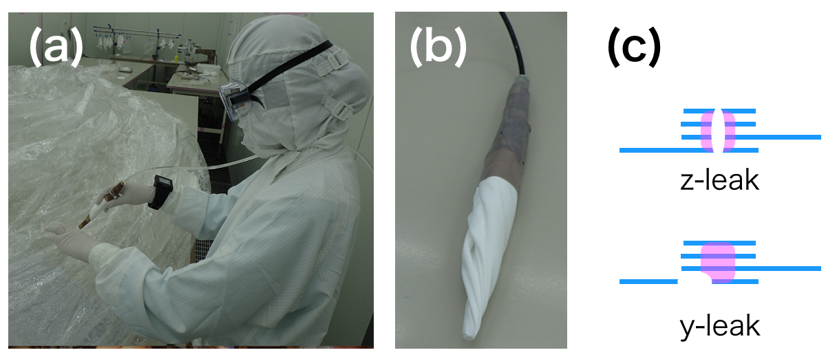
We checked the balloon for leak points by filling it with helium and using helium leak-check detectors (M-222LD-D, Canon Anelva Corporation, and Adixen, Pfeiffer Vacuum GmbH), as shown in Figure 10(a). To avoid introducing dust to the IB surface we covered the helium probes with SFIDA cloth (Figure 10(b)). We found two types of leaks, termed z-leaks and y-leaks, as illustrated by Figure 10(c). The z-leaks appear to be caused by factors including the boiling of water contained in the film, local heat concentration by the NITOFLON® tape adhering to the film, the condition of the heating element, creases in the film, and air remaining between the films. The y-leaks appear to be caused by insufficient welding heat, and also by film creases and local heat concentration. The total number of leak points was about 1,000. Most of these holes were not visible, but they included about 10 holes of about 0.1 mm width and several y-leaks of about 10 mm width.
Two methods were used to repair the leak holes made during film welding, both based on the use of additional nylon film, i.e. re-welding and gluing. The largest leak points, mainly torn parts along welding lines, were repaired with re-welding. However, after repeated re-welds the nylon film becomes harder, and re-welds create weak points susceptible to damage when the film is folded. Therefore most leaks were repaired with glue and small pieces of nylon film (10 mm 10-30 mm). The glue used was Aron Alpha 202 (Toagosei Company, Ltd.). This glue is a single-liquid adhesive that cures at room temperature and humidity, and has high viscosity. It did not adhere to hardened glue, so it could not be used as the primary film connection method, but its properties were suitable for repairing the many small leaks. The glue passed compatibility tests in LS, and ICP-MS measurements at NTT-AT Co. gave an upper limit on the 238U concentration of 510-12 g/g. The surface of the glue hardened in several seconds, but we allowed more than 12 hours for the full area to solidify. The repaired points were checked with the helium leak detector after the glue hardened.
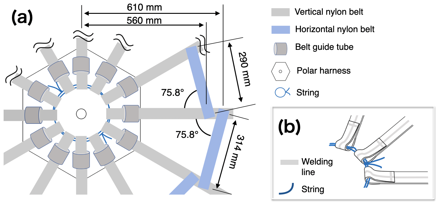
5.8 Hanging belts for the inner balloon
The bottom of the IB rests on the polar harness, which is connected to the 12 load-bearing nylon hanging belts as shown in Figure 2. Figure 11(a) shows a schematic view of the polar area including the belt connections. The polar harness, which has a vent hole at the center, was made from a single layer of nylon film. The purpose of the vent hole was to avoid air getting trapped between the harness and the polar cap during installation, which would lead to light reflection that could bias vertex reconstruction. The belts were made of 2 layers of nylon film welded along the center-line and at their ends. To avoid damage from local tensions, the hanging belts were not directly welded to the polar harness film. The position of the vertical belt is constrained by guide tubes that are also made of nylon film and are glued to the polar harness with Aron Alpha 202. The ends of the 12 belts were welded into loops and connected with 2 Vectran strings (Figure 11(b)). We also connected horizontal belts to the vertical belts near the polar harness with Aron Alpha 202 to constrain the relative position of the belts. The horizontal belts are similar in structure to the vertical belts but their ends were not closed by welding. The position of the belt and harness assembly relative to the polar cap was left unconstrained, as full-size IB installation tests performed for the KamLAND-Zen 400 balloon demonstrated successful positioning of the polar harness directly below the polar cap in four out of four attempts. The belt and harness assembly was set to the IB just before packing and delivery to the detector site.
5.9 Packing
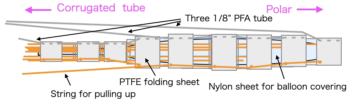
The interior of KamLAND can only be accessed via a narrow opening through the top “chimney” region of the detector (see Figure 1). To pass through this space we folded the IB to within a 50-cm diameter. To protect it from damage and to avoid flexing, especially in the small clean-room above the chimney, the IB was folded and packed inside commercial nylon and PTFE sheets as shown in Figure 12. The PTFE sheets were closed by 1/8” PFA (perfluoroalkoxy alkanes) tubes, released by pulling out the tubes. The strings tied to PTFE and nylon sheets were used to pull up sheets from the detector after sinking the IB (Section 6.5). A custom plastic delivery box was made by the Naigai TEC Corporation. The inner surface was lined with film made by Daizo Corporation (KS137-205). KS137-205 is a 205-m film made of aluminum vapor deposition EVOH with low density polyethylene on both surfaces for gas tightness. After packing the IB inside, the box was set inside a 1.8 m 1.8 m 0.7 m bag made of KS137-205, and it was sealed via welding. This airtight bag kept the balloon in the SCR air and humidity.
6 Installation in the Detector
6.1 Onsite preparation
In order to insert the IB inside the OB, a clean tent was built on the top of the KamLAND detector. The clean-room class grade was between 10–100 (FED-STD-209) depending on the area and the number of people in the tent. The inner surface of the room was cleaned with lint rollers and by wiping with ultra-pure water. The ultra-pure water, with electrical resistivity greater than 18.2 Mcm, was made using reverse osmosis apparatus with a RFU554CA (Advantec MFS, Inc.) filter. It was used for wiping down surfaces, washing gloved hands, and keeping tools clean. The tables, tools, wipers, and other materials were all delivered to the KamLAND site from Sendai after being cleaned and packed in the SCR.
6.2 Corrugated tube connection
A specific procedure was developed and set up in order to assemble the corrugated tube. The individual steps consisted in:
-
1.
Set two O-rings in adjacent “valley” near the end of the corrugated tube (see Figure 3).
-
2.
Insert the corrugated tube into the PEEK connection cylinder.
-
3.
Leak check the connection.
-
4.
Apply Adcoat glue at the edge of the PEEK cylinder.
-
5.
Wait 5 days for the adhesive to harden.
-
6.
Connect the grip piece.
We used two O-rings for each connection because we found that the deformation of the corrugated tube led to leaks when only one was used. We added glue to ensure leak tightness as the O-rings alone may leak (Xe-)LS or gases.
6.3 String guide
The string guide (Figure 2) drives the 12 strings, preventing them from touching the outer balloon or the chimney of the detector, and avoiding any entanglement of the strings themselves. The string guide is positioned under a light-blocking black film at the bottom of the chimney. We located it as high as possible to prevent the nylon support belts from cutting into the IB. The string guide is connected to the corrugated tube. It can be rotated relatively to the fixed corrugated tube to remove any twisting of the balloon or belts and ropes caused by the installation processes.
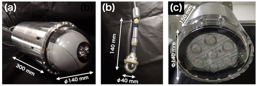
6.4 Monitoring camera
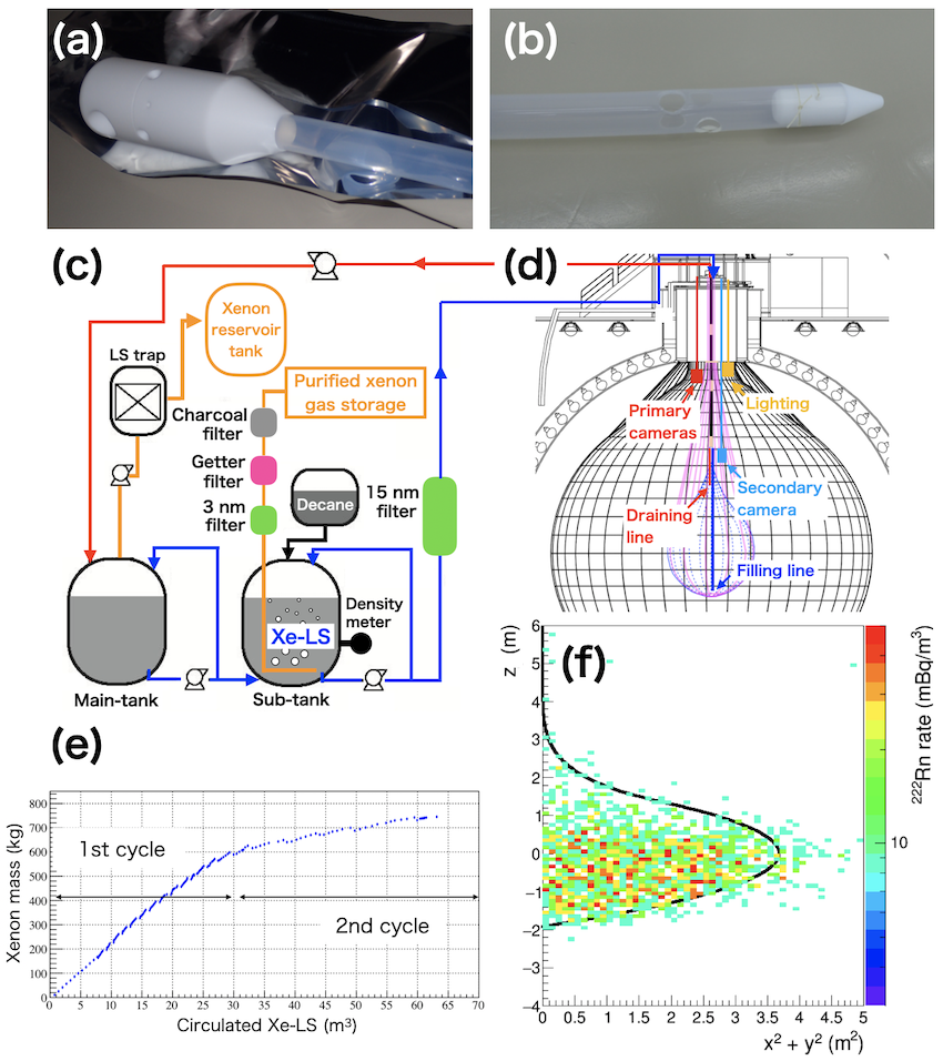
We cannot view the interior of the detector directly through the upper opening because the hole area at the bottom of chimney is covered by black sheets to block light from the outside. We used two monitoring cameras compatible with LS to oversee the IB installation and to ensure the safety of both the IB and the rest of the detector. After the installation, the cameras were used to regularly monitor the condition of the detector and IB for several months. The primary camera, shown in Figure 13(a), is a high-resolution Internet Protocol (IP) camera that can resolve small details and view the whole IB and detector. This camera was covered by a stainless-steel housing and a UV-transparent acrylic dome for use in LS. The power supply and data transfer are through a Power over Ethernet (PoE) LAN cable encased in PFA tubing. The primary monitoring camera was installed before the IB installation and was used to monitor the IB during installation, to monitor balloon expansion during LS filling, to search for signs of leakage, and to assist the positioning and retracting of the filling/draining tube. Figure 13(b) shows the secondary camera, based on a camera designed for pipe inspection (Wöhler VIS 350, Wöhler Technik GmbH). This camera was used to check the vicinity of the IB. The polycarbonate cover dome of this camera was replaced with UV-transparent acrylic for use in the LS. The fiberglass cable was also replaced with one with a fluorine surface compatible with the LS. We also positioned LED lights in the detector, illuminated only while actively monitoring the IB (Figure 13(c)).
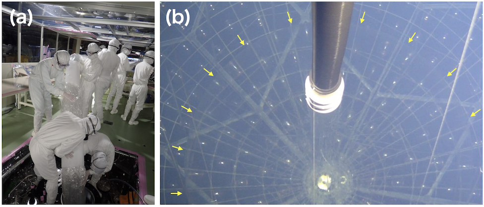
6.5 Installation
The densities of nylon and PTFE are 1.2 g/cm3 and 2.2 g/cm3, respectively, while that of the KamLAND LS is 0.77728 0.00004 g/cm3. Therefore, the IB with its folding covers would ideally sink into the LS. However, due to air remaining in the IB, lowering it into the detector is actually not so easy. We introduced pseudocumene-rich LS with a density of about 0.78 g/cm3 into the IB to extract the residual air and to decrease the balloon’s buoyancy. As we lowered the IB, we repeated the step-by-step filling in 5–10 L increments. We lowered the balloon as shown in Figure 14, keeping the balloon folded in its nylon and PTFE covers (Figure 12). Once this was in position, we removed the 1/8” PFA tubes that secured the PTFE cover sheets so that the sheets would detach from the balloon. We then used the strings attached to the nylon and PTFE covers to pull them up to the access area at the top of the detector and remove them.
6.6 Inner balloon inflation and liquid scintillator filling
The IB was inflated by filling it with decane and pseudocumene based LS (non-Xe-loaded LS) with a density 0.77732 g/cm3. Since the density of LS increases by 0.1%/∘C at temperatures near 10∘C, we maintained the temperature of the added scintillator within the range 9.5–10.5∘C, compared to a temperature at the center of KamLAND of about 12.0∘C. The LS flow rate was about 270 L/hour, and the total volume of LS filled to expand the IB was 30.5 m3. The effective radius of the IB based on the filled non-Xe-loaded LS is 1.90 m.
6.7 Filling of xenon loaded liquid scintillator
The non-Xe-loaded LS was replaced by Xe-LS by circulation after the IB was leak-checked. The leak checked was performed by monitoring the IB weight with load cells, the shape stability was verified with the primary cameras and the decane concentration in the KamLAND-LS was measured using gas chromography. A 3/4” PFA tube was used as a filling line (Figure 15(a)), with its end positioned 200 mm above the bottom of the balloon (Figure 15(d)). A similar tube, whose end is positioned in the cone area, was used as draining line (Figure 15(b)(d)). The xenon was dissolved in the non-Xe-loaded LS removed from the IB by bubbling xenon in a dedicated circulation system (Xe-system, Figure 15(c)). The non-Xe-loaded LS was first degassed in the main tank. Both xenon and decane were then added to the LS in the sub-tank to control the density of the Xe-LS. The Xe-LS was sampled from the sub-tank flow line and the xenon concentration was measured by gas chromatography before filling to the IB. The Xe-LS was tuned to have a density of about 0.77741 g/cm3 and temperature of about 10.5∘C. This Xe-LS had a slightly higher density than the non-Xe-loaded LS in the IB, and this allowed to keep the non-Xe-loaded LS separated from the Xe-LS in the IB. The Xe-LS volume was monitored by 214Bi–214Po coincident events of 222Rn daughter nuclei as shown in Figure 15(f). The source of the 222Rn, whose half-life is 3.8 days, is emanation from the inner surfaces of the stainless steel tanks in the Xe-system, and from the piping between the Xe-system and the PFA tubes at the detector. The Xe-LS and non-Xe-loaded LS flow rate was about 150 L/hour, with about 600 L in one filling batch due to the size of sub-tank in the first cycle. We performed roughly two full volume exchanges of the Xe-LS to maximize the xenon concentration (Figure 15(e)), as some amount of the Xe-LS mixes with the non-Xe-loaded LS at the boundary. We applied continuous Xe-LS circulation between the sub-tank and the IB in the second cycle to maximize the xenon concentration in Xe-LS. The total amount of xenon dissolved into the balloon was measured by the weight of gas storage to be 745 kg, corresponding to 677 kg of 136Xe. This is consistent with the estimate from the Xe-LS xenon concentration analysis by gas chromatography.
7 Inner Balloon Contamination
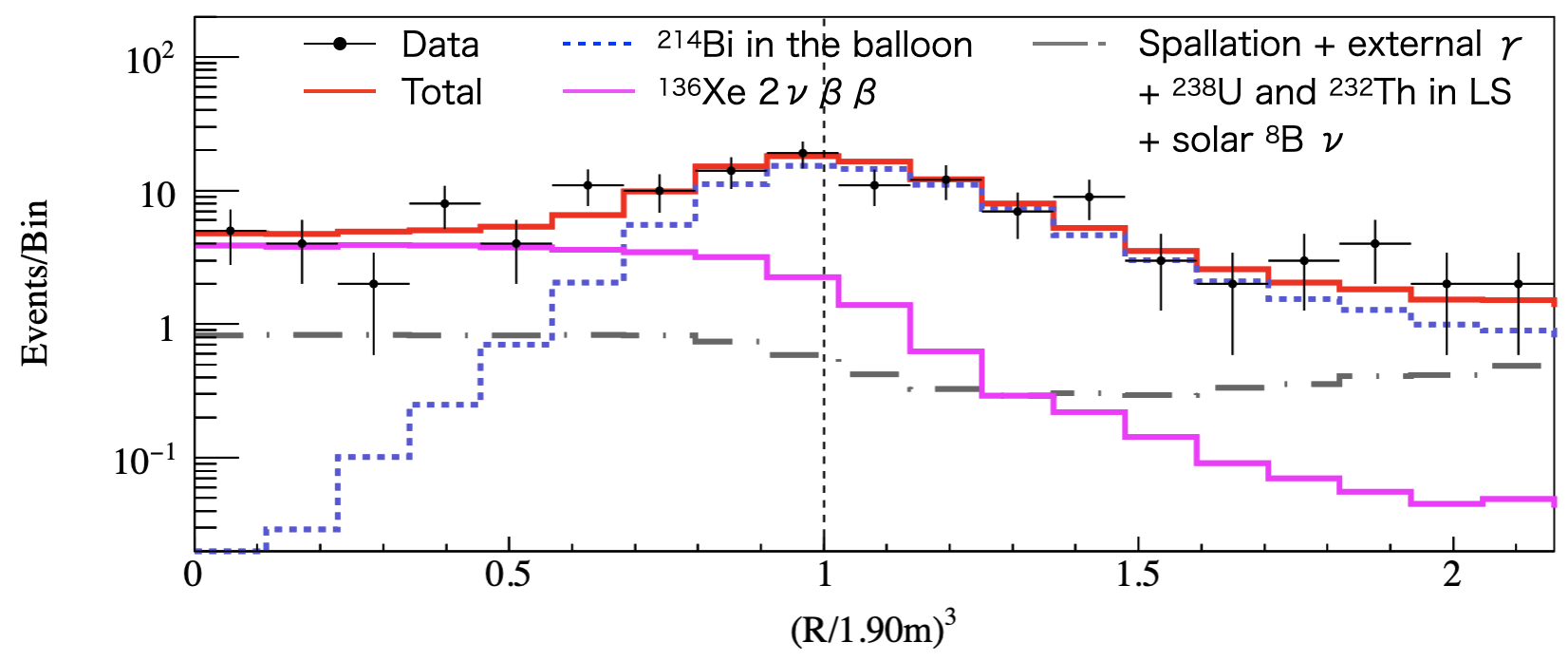
The levels of 238U and 232Th in and on the deployed IB film were assayed in-situ by measuring the excess spectral strength due to these sources reconstructing at the radial position of the balloon surface. Figure 16 shows the radial distribution of events with visible energy range 2.30 MeV to 2.70 MeV, which is dominated by 214Bi decay events. We estimated the number of events of 214Bi and by fitting the observed data simultaneously for both components. The other backgrounds such as muon spallation products, external from the stainless steel containment vessel, 238U and 232Th-series in LS, and solar 8B neutrinos were estimated using the KamLAND LS volume and fixed in the fitting. From this analysis and that of 208Tl, we evaluated 238U and 232Th levels in the IB as 310-12 g/g and 410-11 g/g, respectively. Contamination was reduced by a factor of 10 from the KamLAND-Zen 400 phase of our search [7]. The amount of 238U contamination is consistent with pre-installation measurements of the raw nylon film, thus proving that we succeeded in constructing a new IB without polluting the detector.
Looking ahead, to reach even lower background levels due to radioactive contamination of the IB, we would need to either use cleaner nylon film, produced in a clean-room, or to use a different technique like introducing a self-vetoing balloon made from scintillating material [21].
8 Summary
We fabricated a balloon to contain the xenon-loaded liquid scintillator for the KamLAND-Zen 800 experiment. The balloon was made of nylon film and assembled in an ultra-clean environment. We successfully installed the balloon and inflated it inside the KamLAND detector by filling it with density tuned liquid scintillator without xenon. Finally, we successfully replaced the liquid scintillator with the xenon-loaded liquid scintillator. The 238U contamination of the balloon is consistent with the level in the initial nylon, indicating that we built the balloon without significant additional contamination. This contamination level shows a factor-10 improvement with respect to KamLAND-Zen 400.
Acknowledgments
The authors would like to thank the DAIZO Corporation for developing nylon film welding with us, Toyobo Company for developing and providing the custom-made nylon film, and Creative Design and Engineering for developing secondary welding machine. We are grateful to the institutes and companies described in the main text, all of whom have been critical in the production of the IB and the development of associated technologies. The KamLAND-Zen experiment is supported by JSPS KAKENHI Grants No. 21000001 and No. 26104002; the World Premier International Research Center Initiative (WPI Initiative), MEXT, Japan; Stichting FOM in the Netherlands; and under the U.S. Department of Energy (DOE) Contract No. DE-AC02-05CH11231, as well as other DOE and NSF grants to individual institutions. The Kamioka Mining and Smelting Company has provided service for activities in the mine. We acknowledge the support of NII for SINET4. This work was supported by JSPS KAKENHI Grants No. 21244025, No. 25220704, No. 17H01120, No. 21684008, No. 26287035, and No. 18J10498, NSF Award 1806440 and a UVLAC-Hayashi MISTI Seed Grant. This work was partly supported by the Graduate Program on Physics for the Universe (GP-PU), Tohoku University.
References
- [1] J. Schechter and J. W. F. Valle, Neutrino decay and spontaneous violation of lepton number, Phys. Rev. D 25, 774 (1982).
- [2] P. Minkowski, e at a rate of one out of 109 muon decays?, Phys. Lett. B 67, 421 (1977).
- [3] T. Yanagida, Proc. Workshop on Unified Theory and Baryon Number of the Universe, p. 95 (1979).
- [4] M. Gell-Mann, P. Ramond, and R. Slansky, in Supergravity, eds. P. van Nieuwenhuizen and D. Freedman (North Holland, Amsterdam, 1979).
- [5] M.Fukugita, T.Yanagida, Barygenesis without grand unification, Phys. Lett. B 174, 45 (1986).
- [6] M. Redshaw, E. Wingfield, J. McDaniel, and E. G. Myers, Mass and Double-Beta-Decay Q Value of 136Xe, Phys. Rev. Lett. 98, 053003 (2007).
- [7] A. Gando (KamLAND-Zen Collaboration), Search for Majorana Neutrinos Near the Inverted Mass Hierarchy Region with KamLAND-Zen, Phys. Rev. Lett. 117, 082503 (2016).
- [8] K. Eguchi (KamLAND Collaboration), First Results from KamLAND: Evidence for Reactor Antineutrino Disappearance, Phys. Rev. Lett. 90, 021802 (2003).
- [9] A. Gando (KamLAND Collaboration), Reactor on-off antineutrino measurement with KamLAND, Phys. Rev. D 88, 033001 (2013).
- [10] T. Araki (KamLAND Collaboration), Experimental investigation of geologically produced antineutrinos with KamLAND, Nature 436, 499–503 (2005).
- [11] A. Gando (KamLAND Collaboration), Partial radiogenic heat model for Earth revealed by geoneutrino measurements, Nature geoscience 4, 647–651 (2011).
- [12] S. Abe (KamLAND Collaboration), Measurement of the 8B solar neutrino flux with the KamLAND liquid scintillator detector, Phys. Rev. C 84, 035804 (2011).
- [13] A. Gando (KamLAND Collaboration), 7Be solar neutrino measurement with KamLAND, Phys. Rev. C 92, 055808 (2015).
- [14] A. Gando (KamLAND-Zen Collaboration), Measurement of the double- decay half-life of 136Xe with the KamLAND-Zen experiment, Phys. Rev. C 85, 045504 (2012).
- [15] K. Abe (XMASS Collaboration), Distillation of liquid xenon to remove krypton, Astroparticle Physics 31, 290–296 (2009).
- [16] S. Abe (KamLAND Collaboration), Production of radioactive isotopes through cosmic muon spallation in KamLAND, Phys. Rev. C 81, 025807 (2010).
- [17] Takahiko Hachiya for the KamLAND collaboration, Delayed coincidence with a day-scale window for tagging 232Th series isotopes in KamLAND, J. Phys.: Conf. Ser. 1468 012257 (2020).
- [18] A. Gando, First Results of Neutrinoless Double Beta Decay Search with KamLAND-Zen, Ph.D. Thesis, Tohoku University (2012).
- [19] J. Benziger (BOREXINO Collaboration), The Nylon Scintillator Containment Vessels for the Borexino Solar Neutrino Experiment, Nucl. Instrum. Meth. A 582, 509–534 (2007).
- [20] Kiyoichi Matsumoto, Toshiyuki Kuroki, Rikizo Imamura, MOLECULAR ORIENTATION OF THE BIAXIALLY STRETCHED NYLON-6 FILMS PREPARED BY DRY-PROCESS, Sen’i Gakkaishi, 30, Issue 10, T494-T502 (1974), and private communication with Dr. Katsuya Ito (Toyobo Company).
- [21] S. Obara, Y. Gando, K. Ishidoshiro, Scintillation balloon for neutrinoless double-beta decay search with liquid scintillator detectors, Prog. Theor. Exp. Phys. 073H01, 2019.