∎
University of Glasgow, Glasgow, G12 8QQ, UK
22email: hugh.bird.1@research.gla.ac.uk 33institutetext: Kiran Ramesh 44institutetext: Aerospace Sciences Division, School of Engineering,
University of Glasgow, Glasgow, G12 8QQ, UK
44email: kiran.ramesh@glasgow.ac.uk
Unsteady lifting-line theory and the influence of wake vorticity on aerodynamic loads
Abstract
Frequency domain Unsteady Lifting-Line Theory (ULLT) provides a means by which the aerodynamics of oscillating wings may be studied at low computational cost without neglecting the interacting effects of aspect ratio and oscillation frequency.
Renewed interest in the method has drawn attention to several uncertainties however. Firstly, to what extent is ULLT practically useful for rectangular wings, despite theoretical limitations? And secondly, to what extent is a complicated wake model needed in the outer solution for good accuracy?
This paper aims to answer these questions by presenting a complete ULLT based on the work of Sclavounos, along with a novel ULLT that considers only the streamwise vorticity and a Prandtl-like pseudosteady ULLT. These are compared to Euler CFD for cases of rectangular wings at multiple aspect ratios and oscillation frequencies.
The results of this work establish ULLT as a low computational cost model capable of accounting for interacting finite-wing and oscillation frequency effects, and identify the aspect ratio and frequency regimes where the three ULLTs are most accurate. This research paves the way towards the construction of time-domain or numerical ULLTs which may be augmented to account for non-linearities such as flow separation.
Keywords:
Unsteady lifting-line theory vortex dynamics unsteady aerodynamics1 Nomenclature
| = | Fourier coefficients in 2D bound vorticity distribution |
| \clipbox0pt 0pt .32em 0ptÆR | aspect ratio |
| = | chord |
| = | lift coefficient (2D) |
| = | lift coefficient (3D) |
| = | moment coefficient (2D) |
| = | moment coefficient (3D) |
| = | 3D correction strength |
| = | plunge displacement |
| = | normalized plunge amplitude |
| = | chord reduced frequency |
| = | 3D interaction kernel |
| = | semispan |
| = | time |
| = | free stream velocity |
| = | 2D downwash |
| = | chordwise coordinate |
| = | normalized moment reference location |
| = | normalized pitch location |
| = | spanwise coordinate |
| = | angle of attack |
| = | vorticity per unit area |
| = | bound circulation per unit span |
| = | angular reference coordinate on span |
| = | span reduced frequency |
| = | velocity potential |
| = | angular frequency |
2 Introduction
The unsteady aerodynamics of wings is an increasingly important topic in modern aerospace research. On the smallest of scales, engineers are using flapping wing motions in the design of micro air vehicles (MAVs). At larger scales, oscillatory motion is seen as a means by which energy can be captured from water currents with reduced environmental damageRostami2017 . And at larger scales still, high aspect ratio aircraftWang2010 ; Murua2012a and wind turbine designersHansen2006 face challenges is understanding the consequences of wings flexing under load.
The focus of this article is on finite-wing effects in unsteady aerodynamics. Early research in this topic was strongly motivated by dynamic stall in helicopters mccroskey . Studies in this topic, carried out using Computational Fluid Dynamics (CFD) and experiments are reviewed in Carr carr1988progress , Carr et al. carr2 and Ekaterinaris and Platzer ekaterinaris1998computational . More recent investigations (in the 21st century) into three-dimensional effects in dynamic stall using state-of-the-art experimental and numerical methods include Angulo et al. andreu2019influence and Visbal and Garmann visbal2019dynamic ; visbal2019effect . All these studies concern the forces and flow around a finite aspect ratio wing undergoing pitch-plunge motion in a high Reynolds number, low reduced frequency regime. The modern aerospace applications listed earlier have inspired unsteady aerodynamics research in new regimes, at low/transitional Reynolds numbers and involving high reduced frequencies. These flows are typically massively separated and involve leading-edge vortex (LEV) formation and shedding. Finite-wing effects in these regimes, specifically concerning the interactions of tip vortices with leading- and trailing-edge vortices have been investigated using CFD and experiments, for translating wings mulleners2017flow ; mancini2015unsteady ; devoria2017mechanism , pitching wings jantzen2014vortex ; hord2016leading ; yilmaz2012flow ; yilmaz2010scaling ; visbal2017unsteady ; green2011unsteady , plunging wings calderon2013volumetric ; calderon2014absence ; calderon2013lift ; visbal2013three ; yilmaz2010three ; fishman2017structure , rotating wings ozen2012three ; carr2013finite ; carr2015aspect ; medina2016leading ; beals2015lift ; venkata2013leading and wings subject to gusts perrotta2017unsteady ; corkery2018development ; biler2019experimental . These studies have shed much light on force production in unsteady finite-wings and on the contributions from circulatory, apparent-mass and vortical effects.
Theoretical or low-order methods in aerodynamics are required for rapid design analysis and optimization, and, later on in the engineering cycle, real-time simulation and use in control systems. The development of these is aided and inspired by experimental and computational studies, such as those referenced earlier. In 2D, Theodorsen’s theory theodorsen1935 provides the lift and moment for a thin, symmetric airfoil undergoing small harmonic pitch and plunge oscillations in potential flow. This theory has been shown to provide good results even in regimes outside the expected limit of validity such as at low Reynolds numbers, for large amplitudes of oscillation, and even when LEVs are present (so long as they are attached) mcgowan2011investigations ; ol2009shallow . 2D low-order models based on the discrete-vortex method have been used to successfully predict airfoils undergoing arbitrarily large kinematics and massively-separated flows kiran_journal1 ; ramesh2014discrete .
In 3D, the simplest approach is strip theory Leishman2006 . Neglecting all three dimensional effects (for large aspect ratios) allows two dimensional methods to be applied to the wing in strips. In instances where this is a poor approximation, low-order 3D methods such as the unsteady boundary-element method moored2018unsteady , unsteady vortex lattice method Katz2001 ; Murua2012a ; Smyth2019 ; hirato2019vortex or vortex particle methods willis2007combined can be used, but at far greater computational cost due to the large numbers of interacting vortex elements required to form wake vortex structures. Eldredge and Darakananda Eldredge2015 suggest forming these vortex structures with a very small number of time-varying elements instead, but this introduces difficulties. As with similar 2D models, the lack of natural vortex shedding mechanisms makes such an approach dynamically incomplete for long-term simulations, according to Darakananda and Eldredge Darakananda2018 .
There is however an intermediate to 2D and 3D methods. By augmenting 2D models with corrections gathered from a much simplified 3D model, lifting-line theory may be obtained. By avoiding full three dimensional interaction, the computational complexity of the problem is significantly reduced. Lifting-line theory assumes a high aspect ratio wing. The chord scale and span scale are so far removed that the problem can effectively be separated into detailed inner 2D solutions which interact via a simplified outer 3D solution.
The simplest form of lifting-line theory assumes straight wings and steady flow. PrandtlPrandtl1923 is credited with the earliest lifting-line theory. This was formalized through matched asymptotic expansions by Van DykeDyke1964 and extended to curved and swept wings by GuermondGuermond1990 . Non-linear extensions to steady lifting-line theory have become an important design toolGallay2015 .
The desire for an unsteady lifting-line theory (ULLT) lead to work on the problem of oscillating wings. Such a problem is the three-dimensional analogue of the oscillating plate, analyzed by Theodorsentheodorsen1935 . Assuming a high aspect ratio wing, Cheng cheng1976lifting has identified five frequency ranges based on the wake wavelength , span () and average chord (): (i) very low frequency (), (ii) low frequency (, (iii) intermediate frequency (), (iv) high frequency (), and very high frequencies (). Early authors in this topic such as JamesJames1975 and van HoltenHolten1976 assumed a uniform induced downwash over the chord (as in the steady case) for all frequencies. Ahmadi and WidnallAhmadi1985 showed that this assumption was asymptotically valid only for very low frequencies, and further showed that in the low-frequency regime the induced downwash has a harmonic variation in the chordwise direction. Guermond and SellierGuermond1991 showed that this conclusion is actually true for all frequencies, and also derived a theory applicable for wings with curvature and sweep and uniformly valid for all frequencies. SclavounosSclavounos1987 produced a ULLT that assumes a uniform induced downwash but is claimed to be valid at all but very high frequencies.
All these ULLTs assume harmonic kinematics, small amplitudes of motion, planar wakes, and use Theodorsen’s theory to represent the 2D solution in chordwise strips along the span of the wing. However, unlike in 2D where the frequency-domain solution (Theodorsen) has a time-domain equivalent (Wagner’s indicial response)garrick1938 , it has not yet been possible to derive time-domain equivalents for ULLTs.
Low-order models based on lifting-line theory in the time domain hence employ more assumptions and approximations in comparison with harmonic ULLTs. A common assumption made is to treat the 2D strip-wise solutions as unsteady (using nonlinear inner 2D methods which may apply to non-harmonic kinematics), while treating the trailing vortices behind the wing as steady (in essence, Prandtl’s LLT applied to a time-varying wing circulation distribution). This assumption is referred to as the “pseudosteady assumption” in this article.
The first unsteady finite wing analysis in the time domain is due to JonesJones1939 , although it is only applicable to elliptic planforms. A time-domain ULLT is presented by Boutet and DimitriatisBoutet2018 using an inner solution based on Wagner’s methodWagner1925 , and a pseudosteady assumption. Ramesh et al.Ramesh2017 introduce a lifting-line theory for a geometrically non-linear inner solution, again using a pseudosteady assumption. DevinantDevinant1998 presents a method by which the pseudosteady assumption can be numerically removed for wake wavelengths of the wing span scale or larger. Bird et al.Bird2019 apply this method to a geometrically non-linear inner solution. Sugar-Gabor et al.Sugar-Gabor2018 suggested a method where the unsteady wake was only accounted for in the outer 3D problem, allowing for roll and yaw kinematics. Lifting-line theory has also been used to model wings in large-scale simulations where resolving the chord-scale would be prohibitively expensive, for example in Caprace et al. Caprace2020 .
Strip theory (no 3D effects) and the pseudosteady assumption (steady 3D effects through Prandtl’s LLT) are attractive owing to their mathematical simplicity and easy of implementation. However, the implications of the pseudosteady wake model - or any other simplified wake model - are not well understood. Whilst Guermond and Sellier’s analysis Guermond1991 found that a pseudosteady wake model was only asymptotically valid in the very low frequency regime, the practical implications of this assumption in aerodynamic flows are less clear.
Additionally, only limited validation of unsteady lifting-line theory has been undertaken. Sclavounos Sclavounos1987 and Boutet and Dimitriatis Boutet2018 compared their methods to the unsteady vortex lattice method. This method shares some assumptions with unsteady lifting-line theory, and requires care in discretization to satisfy the Kutta condition Roesler2018 . Sclavounos compared results against the whole-wing lift coefficient of a rectangular and an elliptic wing undergoing oscillating kinematics. Boutet and Dimitriatis examined whole-wing lift and moments for indicial and oscillating kinematics. Guermond and Sellier Guermond1991 compared their work to a panel method for a pointy wing. Much of experimental and CFD work undertaken on oscillating wings (listed earlier) post-dates publication of unsteady lifting-line theories. These works show that the vortical topology of the wake is far more complex than might be assumed, even at relatively low amplitudes.
Therefore, this paper firstly investigates the accuracy of a ULLT based upon Sclavounos’ interaction kernel in comparison to CFD for rectangular wings oscillating in heave and pitch. The use of Euler CFD avoids the explicit assumptions of unsteady vortex lattice methods used in previous research. Whilst lifting-line theory is not strictly valid in the context of rectangular wings Dyke1964 , they are of great practical relevance.
Secondly, this paper modifies this ‘complete’ ULLT in order to investigate the effects of simplified wake models and the accuracy of frequency domain unsteady lifting-line theory. The work is based upon a framework similar to that of Sclavounos because of its arrangement as the solution of an integro-differential equation (akin to Prandtl’s LLT), unlike the work of Van DykeDyke1964 or Guermond and SellierGuermond1991 . This also makes it more amenable to modification of the 3D interaction kernel. Understanding the trade-off between wake-model complexity and ULLT accuracy is useful for those building more complex numerical ULLTs.
The article is therefore laid out as follows: in section 3, ULLT is introduced, based upon the framework of Sclavounos with minor modifications. The 3D interaction kernel and alternative forms of the kernel representing different wake assumptions are discussed in section 3.4. The ‘complete’ ULLT is validated against CFD in heave and pitch for the Euler regime in section 4.1.1. Next, the impact of using simplified ULLTs is explored for whole wing loads in section 4.1.2, the wake vorticity distribution in section 4.1.3, and wing load distributions in section 4.1.4. A brief discussion of the results obtained using the simplified wakes is then given in section 4.1.5. Section 4.2 compares the ULLTs to experimental data, confirming that ULLTs are relevant even when the flow is not inviscid before the conclusions are finally presented in section 5.
3 Theoretical approach
Sclavounos’ ULLT considers potential flow past a thin, unswept wing subject to a uniform freestream velocity () and undergoing small-amplitude, harmonic pitch () and plunge () oscillations. The problem is formulated with an outer and inner domain. At distances from the wing that are large compared to its chord (outer domain), the flow is insensitive to the wing geometry. The perturbation due to the wing may hence be approximated by a line of concentrated bound circulation along the -axis and a planar trailing vortex sheet representing the shed wake. At distances from the wing comparable to the average chord (inner domain), the problem is reduced to a sequence of airfoil sections undergoing small-amplitude oscillations in pitch and plunge (Theodorsen’s problem). The final unsteady lifting-line solution is obtained by matching asymptotic expansions of the inner and outer solutions.
In section 3.1, Sclavounos’ derivation of the outer solution is reproduced and the kernel representing the unsteady induced downwash is introduced. In section 3.2, the inner solution from Theodorsen’s theory is presented in terms of a general unsteady thin-airfoil formulation. Matching of the inner and outer asymptotic expansions and the final lifting-line equation (from Sclavounos) are presented in section 3.3. Finally, the kernel and the influence of the various wake models on the same are discussed in section 3.4.
3.1 The outer solution
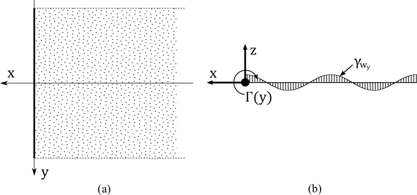
The lifting line and its oscillating wake as seen in the outer domain are illustrated in figure 1.
The bound vorticity / circulation of the wing is described by the complex quantity,
| (1) |
Kelvin’s theorem dictates that the change in bound circulation is convected into the wake. Hence the spanwise () and streamwise () wake vorticity at the wing trailing-edge are
| (2) | ||||
| (3) |
Vorticity is convected only by the free stream, hence
| (4) |
Now consider a two dimensional slice in the - plane, as shown in figure 1b. From this perspective, the lifting-line appears as a point vortex, with a wake on , .
It is in this plane that the Kelvin condition for spanwise circulation, given by equation 2, is satisfied. For a bound circulation of unit amplitude, the velocity potential is given by
| (5) |
The first term represents the bound circulation at origin and the second term represents the 2D wake vortex sheet.
The streamwise vorticity, , due to equation 3 must still be included. The effects of this are given as the second term in the asymptotic expansion of the full outer velocity potential equation, derived by Sclavounos as
| (6) |
where the kernel will be discussed in section 3.4. This second term represents an unsteady downwash accounting for the 3D interaction in the outer domain. Differentiating this term with respect to gives the induced downwash due to finite wing effects. Since this second term is invariant with respect to and linear in , the downwash at any spanwise location is uniform in the - plane over the section chord. This is a simplification that restricts the asymptotic validity of the theory to span-scale wake wavelengths and longer (very-low and low frequencies) according to Guermond and SellierGuermond1991 . The effect of this assumption in predicting loads on the wing are investigated and discussed in section 4 by comparing lift coefficients from ULLT against numerical simulations over a large frequency range.
3.2 The inner solution
In the inner domain, the detail of the flow around a chord section is considered. Since it is assumed that , and that changes in the flow happen on the span length-scale, the problem can be considered as 2D. The problem consists of a symmetric airfoil at a certain spanwise section undergoing small-amplitude pitch and plunge oscillations,
| (7) | ||||
where is plunge amplitude per unit chord, is pitch amplitude, is the phase between plunge and pitch, and is the frequency of oscillation typically expressed as a chordwise or spanwise reduced frequency
| (8) |
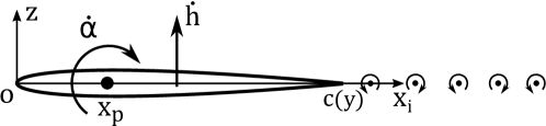
Figure 2 shows this problem, for which the solution is given by Theodorsentheodorsen1935 . The results are expressed here in terms of a general unsteady thin-airfoil theoryKatz2001 ; kiran_journal1 which allows easy modification of the approach for various wing geometries and kinematics. The bound vorticity distribution over the airfoil section is taken as a Fourier series
| (9) |
where is a transformation variable related to the chordwise coordinate as , and , … are time-dependent Fourier coefficients that vary over the span. The term represents the suction peak caused by the flow having turn around the airfoil leading edge, and the Kutta condition (zero vorticity at the trailing-edge) is enforced implicitly through the form of the Fourier series. The Fourier coefficients are determined by enforcing the zero-normal-flow boundary condition on the aerofoil chord line.
The bound airfoil circulation and the sectional lift and pitching moment coefficient from unsteady thin-airfoil theory are given by
| (10) | ||||
| (11) | ||||
| (12) | ||||
where is the reference location per chord (ranging from ) about which the pitching moment is calculated.
Rameshramesh2020leading has derived the Fourier coefficients corresponding to Theodorsen’s solution as
| (13) |
where is Theodorsen’s function,
| (14) |
and S(k) is the Sears function,
| (15) |
where and are modified Bessel functions of the second kind Olver2010 . are wake coefficients,
| (16) |
and is the normal downwash at the airfoil three-quarter chord location, calculated from the kinematics as
| (17) |
Using equations 7 and 17, the 2D normal downwash at three-quarter chord location at any spanwise location from plunge and pitch are
| (18) | ||||
| (19) |
The 2D bound circulation, lift coefficient and moment coefficient for pitch and plunge kinematics at any spanwise location are calculated from equations 10, 11, 12, 13, 18 and 19 as
| (20) | ||||
| (21) | ||||
| (22) | ||||
| (23) | ||||
| (24) | ||||
| (25) |
where and are Hankel functions of the second kind, and is the pivot location.
3.3 Matching of the inner and outer solutions
The asymptotic inner expansion of the outer solution velocity potential is given in equation 6. For the inner solution, the velocity potential is constructed as a combination of homogeneous and particular solutions Sclavounos1987 . The homogeneous solution (to model 3D induced effects) is determined from the interaction of the airfoil with a uniform downwash, and the particular solution is obtained from the 2D solutions for pitch and plunge kinematics derived above.
| (26) |
where the first and second terms are the particular and homogeneous solutions, respectively. The uniform downwash corresponds to unit plunge amplitude for which the associated velocity potential is with resulting bound circulation . The outer expansion of the inner velocity potential at large distances from the chord is given as
| (27) |
The outer and inner expansions, equations 6 and 27, may now be matched. Equating the terms allows an expression for the bound circulation distribution to be extracted as
| (28) |
leaving
| (29) |
The contributions to circulation from pitch and plunge may be added together since the theory is linear. The lifting-line integro-differential equation for the time-varying spanwise circulation is obtained from equations 28 and 29 as
| (30) |
We note that all terms in the lifting-line equation contain the common factor . An approximate solution for the complex circulation amplitude (y) can be obtained by expressing it in a Fourier series
| (31) |
where . For problems where both the kinematics and planform of the wing are symmetric about , the even terms can be neglected. For a rectangular wing, the problem is then reduced to numerically solving the equation,
| (32) |
at collocation points distributed over the span. The 3D induced downwash is given by
| (33) |
The Fourier solutions representing the inner solutions across the span may then be corrected for 3D effects by evaluating equation 13 with the total 3D downwash at the three-quarter chord location
| (34) |
The allows the calculation of the stripwise circulation, lift coefficient and pitching moment (accounting for 3D effects) from equations 10, 11 and 12. The wing lift and pitching moment are
| (35) |
where the 2D coefficients have been corrected to include the 3D correction as .
3.4 The kernel
The kernel , first introduced in equation 6, represents the spanwise interaction of the inner solutions. It must account for the difference between the inner solution, that assumes that the flow is 2D, and the actual 3D nature of the problem via the outer solution. The kernels based on various underlying assumptions considered in this article are expressed below in terms of the non-dimensional spanwise distance .
For strip theory, all three dimensional interaction is neglected. The spanwise wake vorticity is modeled in the inner solution, but the strip theory outer solution neglects both the shed streamwise vorticity , and the correction for the fact that the variation of over the span of the wing is not captured by the inner solution. Since all interaction between the inner domains is neglected, the strip theory kernel is
| (36) |
A pseudosteady kernel accounts for the shed streamwise vorticity in the outer domain, as given by equation 3. However, it neglects the sinusoidal variation with respect to downstream coordinate given in equation 4. Again, the variation in with respect to span is not corrected for. The resultant pseudosteady kernel is equivalent to that of Prandtl:
| (37) |
and the ULLT based on this kernel is abbreviated P-ULLT.
If the sinusoidal variation of with respect to given by equation 4 is accounted for the streamwise vorticity kernel can be obtained. The Biot-Savart law can be applied to the streamwise vorticity field. The downwash on a point of the wing at due to a section of the wing is therefore
allowing to be obtained as
| (38) |
where and are the modified Bessel functions of the first and second kind respectively, and is the modified Struve functionOlver2010 . Once again this neglects variation in with repect to span in the outer solution. The ULLT based on this kernel is referred to the simplified ULLT (S-ULLT).
Sclavounos obtained a kernel that accounts for both the shed streamwise vorticity and the 3D correction to the effects of the shed spanwise vorticity .
| (39) |
where is the exponential integralOlver2010 and
| (40) |
The ULLT using Sclavounos’ full kernel is denoted as the complete ULLT (C-ULLT) in this research.
The different ULLT models described above may be summarized in terms of the way the wake is modeled in the outer solution as shown in table 2.
| Method | Kernel | Wake model in outer solution |
|---|---|---|
| Strip theory | : No model | |
| : No model | ||
| P-ULLT | : No model | |
| (Pseudosteady) | : constant with respect to -coordinate | |
| S-ULLT | : No model | |
| (Simplified) | : harmonic variation in -direction | |
| C-ULLT | : harmonic variation in -direction | |
| (Complete) | : harmonic variation in -direction |
At low frequencies the unsteady solution approaches the pseudosteady solution. Accordingly
| (41) |
As the oscillation frequency tends to infinity, 3D effects become negligible, and the kernels that include sinusoidal variation of the shed wake approach the strip theory solution:
| (42) |
4 Results
ULLT is derived from potential-flow theory based on incompressible flow with zero viscosity, and employs further simplifying assumptions of high aspect ratio and low reduced frequency. To determine the range of validity of ULLT across the relevant range of aspect ratio and reduced frequency, and to study the influence of the simplified wake models on the solution, the ULLT is first compared against numerical computations of the incompressible Euler equations. In section 4.2, the ULLT models are validated against previously published experimental data in realistic aerodynamic conditions. Comparative remarks about the ULLTs are then made in section 4.1.5.
4.1 Analysis with Euler Computational Fluid Dynamics
Numerical computations of the unsteady incompressible Euler equations are performed using the open-source CFD toolbox OpenFOAM. A body-fitted, structured computational mesh is moved according to prescribed plunge and pitch kinematics, and the time-dependent governing equations are solved using a finite volume method. A second-order backward implicit scheme is used to discretize the time derivatives, and second-order limited Gaussian integration schemes are used for the gradient, divergence and Laplacian terms. The pressure implicit with splitting of operators (PISO) algorithm implements pressure-velocity coupling. This in-house setup has previously been used with the incompressible Navier-Stokes governing equations to study leading-edge vortex shedding on finite wings bird2018theoretical ; Bird2019 , and with the incompressible Euler equations to verify unsteady potential flow solutions for an airfoil ramesh2020leading .
In this section, we use Euler CFD solutions to validate the 3D aerodynamic loads obtained from ULLT, and to study the influence of ULLT wake models on the loads and load distributions. In the CFD setup, inviscid flow is considered with kinematic viscosity set to zero, and a slip boundary condition is employed for the moving wing surface. A NACA0004 section is chosen to best match the theoretical assumptions of thin section and Kutta condition at the trailing edge.
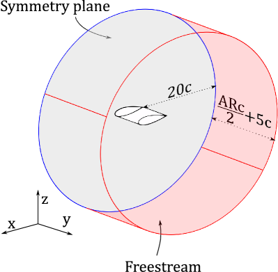
Three aspect ratios (8, 4, and 2) are considered. Cylindrical O-meshes for half the wings are constructed since the pitch and plunge kinematics considered are all symmetric about the wing root. The meshes have cells around the wing section, with increased resolution near the leading and trailing edges. The wall-normal direction has cells with the far-field extending chord lengths in all directions around the section. In the spanwise direction, the aspect ratio 8, 4 and 2 wings have , and cells respectively over the wing, with increased resolution near the wingtip. For all three wings, the spanwise domain extends 5 chord lengths beyond the wingtip, with cells in this region. A diagram of the mesh is shown in Fig. 3. Symmetry boundary condition is used for the circular domain at the wing root, and freestream (inlet/outlet) boundary conditions are used at the spanwise and wall-normal far-field domains. The freestream boundary condition behaves as a zero-gradient condition when fluid is flowing out of the boundary face, and as a fixed value condition (equal to freestream) when fluid is not flowing out.
Harmonic pitch and heave kinematics with chord reduced frequencies of 0.0, 0.125, 0.25, 0.5, 1.0 and 1.5 were simulated. Small amplitudes of oscillation, for plunge and for pitch were used, again to best satisfy the theoretical assumptions and ensure attached flows. The CFD cases are shown in table 3.
| Property | Value |
|---|---|
| Kinematics type | Heave, pitch about leading edge |
| Wing planform | Rectangular |
| Aspect ratio (\clipbox0pt 0pt .32em 0ptÆR) | 2, 4, 8 |
| Chord reduced frequency () | 0.0, 0.125, 0.25, 0.5, 1.0, 1.5 |
4.1.1 Validation of lift and moment coefficients from C-ULLT
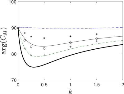
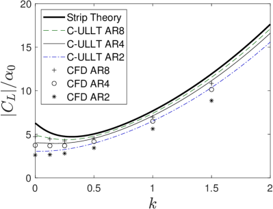
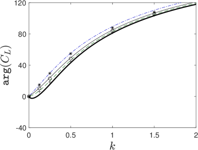
In this section the and (about mid-chord) obtained from Sclavounos’ complete ULLT are validated against the results obtained using CFD for heave and pitch kinematics. For both heave and pitch, the loads are normalized by the oscillation amplitude (since ULLT is linear with respect to this parameter) and the wing has a zero mean pitch angle. For heave, the loads are further normalized by the chord reduced frequency () since as seen in equations 22 and 24, it is a common multiplier for and (unlike for pitch). This is done to better differentiate the various curves at low frequencies as seen below.
Heaving kinematics
The normalized amplitude and phase of the wing lift and moment coefficients for heave oscillations cases are shown in figure 4. The theoretical results and the CFD results are shown by lines and points respectively. Strip theory (2D Theodorsen solution) is also shown by the bold line as a reference; the differences between strip theory and the three ULLT curves show the influence of 3D unsteady induced downwash.
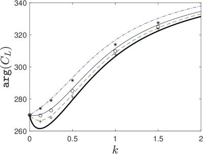
Examining the result from the CFD in figure 4(a), the normalized lift is lower for lower aspect ratios across all frequencies. In the frequency range approximately under , decreases for \clipbox0pt 0pt .32em 0ptÆRs 8 and 4, and remains roughly constant for \clipbox0pt 0pt .32em 0ptÆR2. Above this frequency, the curve increases for all \clipbox0pt 0pt .32em 0ptÆRs, with the gradients of the curves being slightly smaller for lower aspect ratios.
The C-ULLT (Sclavounos’ complete ULLT) results in figure 4(a) broadly predict the trends found in CFD. In the regime where ULLT assumptions are best satisfied, at high aspect ratio 8 and for low frequencies, the comparison with CFD is excellent. As aspect ratio decreases and as frequency increases, the prediction worsens. At low frequencies, the errors in C-ULLT predictions for \clipbox0pt 0pt .32em 0ptÆR4 are relatively small but larger for \clipbox0pt 0pt .32em 0ptÆR2. As frequency increases, C-ULLT follows the trends of the curves from CFD, but overpredicts . there is also an overestimation of the gradient, suggesting that added mass is overpredicted by C-ULLT. This error increases as aspect ratio becomes smaller. It is likely that this error is caused by the ULLT assumption of 2D flow near the wing tips. This assumption is broken for rectangular and elliptic wings.
The phase of wing lift coefficient from CFD and C-ULLT are compared in figure 4(b) . In the limit of low frequency, the C-ULLT predicts that all aspect ratios would have the same phase lag of , but that the response of the phase with increasing would be different according to aspect ratio. Higher aspect ratios increase the phase lag, whilst lower aspect ratios decrease it. These trends agree well with the CFD results. As frequency increases, the phase prediction obtained for higher aspect ratios remains good but an offset is seen for the \clipbox0pt 0pt .32em 0ptÆR2 case.
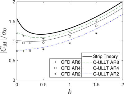
The comparison of normalized pitching moment between C-ULLT and CFD is shown in figure 4(c). Similar to lift, the predictions are best for the high aspect ratio 8 wing. As \clipbox0pt 0pt .32em 0ptÆR decreases, the error increases, particularly at high frequencies. In both CFD and C-ULLT, the curve approaches a limiting value with increasing . However, contrary to the CFD results, the C-ULLT predicts that this value is independent of aspect ratio.
For the phase of shown in figure 4(d), the CFD shows that at all aspect ratios, the phase lead of initially decreases with . This phase lead then starts increasing again in the region of . C-ULLT predicts the trends of the CFD correctly, particularly in the expected regime of validity (high aspect ratio, ).
Overall, the C-ULLT predicts the results and trends of the CFD reasonably well, albeit worse at low aspect ratio. Importantly however, even at such lower aspect ratios, it always provided a better prediction of the CFD result than could be obtained using strip theory.
Pitching kinematics
Next, the C-ULLT is validated against CFD for leading-edge pitching kinematics. The amplitude and phase of lift and moment coefficients for the pitch oscillations cases are shown in figure 5.

The CFD result for the normalized lift amplitude in figure 5(a) initially decreases with respect to at aspect ratio 8, stays constant at aspect ratio 4 and increases slightly at aspect ratio 2 (until about ). Lower aspect ratio leads to a lower . As increases further, increases super-linearly. C-ULLT reflects the trends of the CFD, with the initial gradient and y-intercept being dependent upon aspect ratio. C-ULLT obtains a better prediction for all frequencies with increasing aspect ratio, with errors increasing with higher frequencies.
The CFD data in figure 5(b) shows that initially the starts in phase to the kinematics. As the frequency increases a phase lead develops. Lower aspect ratios result in a larger phase lead. The phase of is excellently predicted by C-ULLT at aspect ratio 8. The accuracy of the prediction worsens at lower aspect ratio, but it remains good, qualitatively reflecting the trends of the CFD.
CFD results for the normalized pitching moment amplitude in figure 5(c) show that is lower for lower aspect ratios. C-ULLT correctly predicts the trends of the CFD. For high aspect ratio, it constantly over-predicts the CFD result by a small amount. At lower aspect ratios, the over-prediction is initially small before growing.
In figure 5(d), CFD shows that is initially approximately in phase with the kinematics. As frequency increases, the leads the kinematics. At low frequencies, the higher aspect ratios have lower phase lead. As frequency increase the phases become more similar, approximately converging at . As frequency increases further, the higher aspect ratios develop larger phase lead than the lower aspect ratios cases. C-ULLT provides a good prediction of the aspect ratio 8 and 4 results at approximately . As frequency increases, the prediction of C-ULLT worsens. Contrary to the CFD result, it predicts that the phase lead of always decreases with aspect ratio.
Overall, it was found that C-ULLT was capable of predicting the CFD results with good accuracy for rectangular wing pitching about the leading edge. The C-ULLT always provided a better prediction of the CFD results than strip theory, and was most accurate for \clipbox0pt 0pt .32em 0ptÆRs 4 and 8 with .
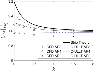
4.1.2 Influence of ULLT kernel on lift coefficient
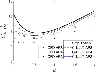
In section 4.1.1 it was found that the agreement between CFD and Sclavounos’ complete ULLT was reasonably good for both lift and moment coefficients, for both pitching and heaving kinematics. The agreement was excellent in the “ideal” regime (for ULLT) of high aspect ratio and low chord reduced frequency. In section 3.4 alternate ULLT models with approximated kernels representing the 3D unsteady induced downwash were introduced. These were the S-ULLT (simplified) and the P-ULLT (pseudosteady), whose assumptions are summarized in table 2. In this section, the implications of approximating the ULLT wake model/kernel are investigated by comparing the normalized lift coefficient amplitude from all three ULLTs against CFD for heaving kinematics. Figure 6 shows the curves for the three aspect ratios of wing studied, across a range of chord reduced frequencies.
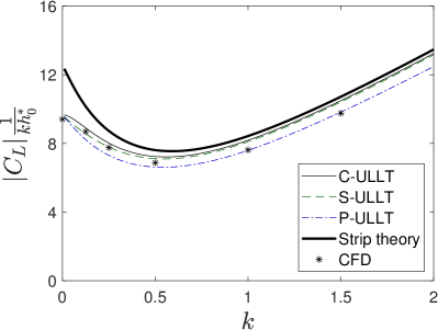

All of the ULLTs predict the same low frequency limit - an expected property due to the interaction kernels of the C-ULLT and the S-ULLT becoming equivalent to the P-ULLT kernel in the low frequency limit. This limiting value reduces with aspect ratio of the wing. For all \clipbox0pt 0pt .32em 0ptÆRs in general, the prediction from C-ULLT is larger in value than that from S-ULLT, which in turn is larger than the prediction from P-ULLT. All methods show an initial negative slope in the normalized amplitude until , and a positive slope thereafter.
At high frequencies , has a linear slope in all 3 ULLT. This is owing to the fact that the added mass contribution to , which varies linearly with (see equation 22), is dominant at high frequencies. The curves for the C-ULLT and the S-ULLT converge due to their identical high frequency limiting behavior. With sufficiently high , they will converge with strip theory. The P-ULLT predicts a slightly lower gradient. The interaction kernel of the P-ULLT does not have a zero high frequency limit. Consequently, even at high frequency there is an erroneous 3D downwash correction, which luckily results in a better agreement with the results from CFD in this regime. This luck may be specific to the rectangular wing planforms studied in this paper. For wing planforms where the assumptions of ULLT are satisfied, this downwash would introduce error.
Looking specifically at the \clipbox0pt 0pt .32em 0ptÆR8 results presented in figure 6(a), initially the C-ULLT and the S-ULLT give a good prediction of the CFD result and the P-ULLT under-predicts the result. As frequency increases, the C-ULLT and the S-ULLT over-predict with the over-prediction increasing with frequency. The P-ULLT provides the best match compared to the CFD result out of the ULLTs at .
As aspect ratios decrease, as shown in figures 6(b) and 6(c) for \clipbox0pt 0pt .32em 0ptÆRs 4 and 2 respectively, there are two major trends of note.
Firstly, the initial negative slope of the curves decreases, and there is a greater difference between the C-ULLT and S-ULLT curves. The difference between the C-ULLT and the S-ULLT curves represent the failure to correct for the changing wake distribution with respect to span in the outer domain of the S-ULLT. At lower aspect ratios, these corrections accounting for finite-wing effects become more important.
Secondly, the ULLTs appear to increasingly over-predict the low frequency limit with decreasing aspect ratio. This effect is most prominent at aspect ratio 2, but explains why at aspect ratio 4 the S-ULLT unexpectedly appears superior to the C-ULLT. Lifting-line theory is based on the assumption of high aspect ratio, so increasing error with decreasing aspect ratio is expected.
Summarizing, all the ULLTs provide a better prediction of the CFD results than the strip theory (2D Theodorsen) result. In regimes where the basic ULLT assumptions of high \clipbox0pt 0pt .32em 0ptÆR and low are satisfied, the complete C-ULLT provides the best predictions. For lower \clipbox0pt 0pt .32em 0ptÆRs at low frequencies (), the simplified S-ULLT provided better predictions than C-ULLT. At high frequencies , for all aspect ratios in general, the pseudosteady P-ULLT provides the best results. This is because the 3D unsteady induced downwash in this method doesn’t tend to zero at high frequencies (unlike in the other two ULLTs), which better reflects the results from Euler CFD.
4.1.3 Comparison of wake topologies in the ULLT kernels
| CFD |
|
|
| C-ULLT |
|

|
| S-ULLT |
|

|
| P-ULLT |
|
|
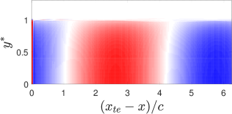
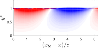
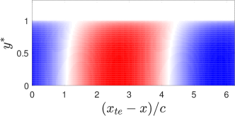
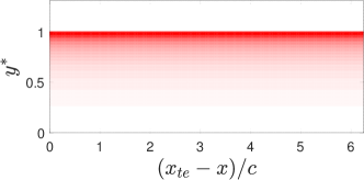
To better illustrate the differences between the wake approximations in the three ULLTs, the vortex sheet strength in the wake from CFD was compared against the vortex sheet strength assumed for the outer domain of the ULLTs. This is shown in figure 7 for the \clipbox0pt 0pt .32em 0ptÆR4 wing oscillating in heave with .
To obtain the plotted data from the CFD cases, the vorticity was integrated over a line in the direction at each point on the - plane. For ULLTs, the vorticity as assumed in the outer domain is shown.
The C-ULLT predicts the CFD results well. Some error is introduced, as would be expected, near to the wing tip. This error is most visible in the plots. In the C-ULLT, a singular distribution of is predicted due to the assumed remapped Fourier distribution of bound circulation. In the CFD, this streamwise wake vorticity remains finite, instead spreading out. In the plots of , the error near the wing tip in the C-ULLT prediction is most visible when comparing the difference in phase between the vorticity at the center of the span and at the tip. In the C-ULLT result, there is a larger phase difference than is observed in the CFD results.
The S-ULLT produces a similar field to the C-ULLT. There is a small phase difference between the C-ULLT result and the S-ULLT result. At the wing tip, where the streamwise vorticity has the greatest amplitude, the phase is very similar however. The S-ULLT does not model in the outer domain. Whilst is included in the inner domain, there is no correction for its variation over the span. This applies to the P-ULLT as well.
The P-ULLT also doesn’t account for the sinusoidal variation of in the outer wake. However, it roughly matches the CFD distribution close to the wing (up to about 2 chord lengths from the trailing edge). Since the vorticity closer to the wing has a larger impact on the induced downwash, the P-ULLT obtains reasonable solutions despite this assumption.
4.1.4 Influence of ULLT kernel on spanwise lift distribution
An advantage of ULLT over strip theory is that it accounts for finite wing effects (with bound circulation going to zero at the wingtips) when computing force distributions over the wing. For aeroelastic analysis (for which strip theory is often used), these load distributions are of importance. This section compares the lift distributions obtained using the three ULLTs against that obtained from Euler CFD.
The distribution of lift and changes with respect to oscillation frequency. This occurs because of the growing importance of added mass-effects with increasing oscillation frequency, and also because of the dependence of the 3D interaction kernel on span reduced frequency . For the C-ULLT and the S-ULLT the 3D unsteady induced downwash tends to zero as frequency increases.
To compare unsteady lifting-line theory to CFD, the lift distribution was extracted from the CFD data at 8 equispaced time instants over a single oscillation. A sine wave was then fitted to the data using a least squares method to determine the amplitude.
The lift distributions will be compared for rectangular wings of aspect ratios 8, 4 and 2 for heaving oscillations at three different chord reduced frequencies. First, a low frequency where C-ULLT provides the best agreement with CFD (so long as aspect ratio is high) is studied. Next, a high frequency where added-mass effects dominate and where P-ULLT was seen to make the best predictions is studied. Finally, an intermediate frequency where the loads are influenced strongly by both circulatory and added-mass effects is examined.
Low frequency behavior
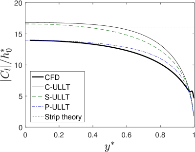
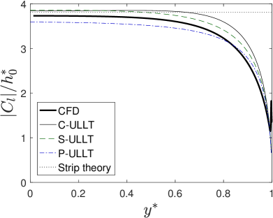
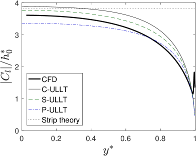
The lift distribution amplitudes from ULLTs are compared against Euler CFD and strip theory for the low frequency case () in figure 8.
The CFD results show a mostly smooth distribution of lift coefficient, with the maximum being found at the wing root (). Near the tip, starts to decrease ever more rapidly, excepting a spike at the very wing tip. This is caused by separation at the sharp edges of the wing tip.
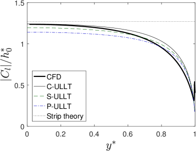
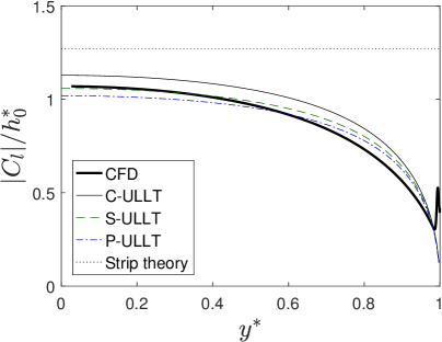
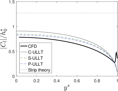
The difference between the curves predicted by the different ULLTs at is small due the fact that they all tend to the P-ULLT kernel as frequency decreases. The results obtained by the C-ULLT and S-ULLT are in particular more similar. The C-ULLT predicts the highest followed by the S-ULLT and then the P-ULLT.
At aspect ratio 8 where ULLT is expected to be most valid, the C-ULLT matches the CFD result well in the center of the wing but has increasing errors as the wing tip is approached. As aspect ratio decreases, the C-ULLT over-predicts the at the center of the wing. Consequently at aspect ratio 4 either the S-ULLT or the P-ULLT provides the best prediction of the CFD result. At aspect ratio 2, all of the ULLTs over-predict . The P-ULLT, which always gives the lowest , is therefore is closest to the CFD result. In all cases, ULLT is superior to strip theory.
High frequency behavior
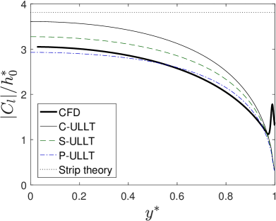
Figure 9 shows a comparison of CFD and ULLT lift distribution predictions for the high frequency case .
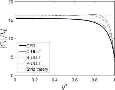

In section 4.1.2, it has been noted that the pseudosteady ULLT gives the best results at high frequencies, as the incorrectly modeled downwash inadvertently reduced the lift overestimate due to the lifting-line assumption being poor at rectangular wing tips. This is further confirmed in figure 9; P-ULLT agrees best with CFD for all three aspect ratios while C-ULLT and S-ULLT over-predict the lift distribution. For \clipbox0pt 0pt .32em 0ptÆR8, the P-ULLT prediction matches with CFD over most of the wing, until . As aspect ratio decreases, the distance from the wingtip where errors are present increases, as expected.
Intermediate frequency behavior
In the intermediate frequency range, the choice of best ULLT model is less clear. Figure 10 shows a comparison of CFD and ULLT lift distribution predictions at , where added-mass and circulatory effects are equally important.
The C-ULLT lift distribution curves have the same shape as those from CFD at all aspect ratios. However, there is an offset which increases as aspect ratio decreases. The simplified S-ULLT which in general predicts lower lift values than C-ULLT hence provides better predictions for \clipbox0pt 0pt .32em 0ptÆRs 8 and 4. P-ULLT which always predicts lower lift values than both C-ULLT and S-ULLT, provides the best prediction for AR2.
4.1.5 Choice of ULLT kernel
The comparison of ULLT models against CFD in section 4.1 provides guidance on choosing the most suitable ULLT depending on the problem parameters. In the regime where the assumptions used in ULLT perturbation analysis are best satisfied, i.e. at high aspect ratio and low chord reduced frequency, Sclavounos’ C-ULLT works best. On the other hand, at high chord reduced frequencies, for all aspect ratios, the pseudosteady P-ULLT provides the best predictions. P-ULLT also provides better predictions than the other two ULLTs at low aspect ratio, across all frequencies. At higher aspect ratios and at intermediate frequencies, the S-ULLT prediction (which lies between the C-ULLT and P-ULLT predictions) provides the best agreement with CFD. The superiority of the P-ULLT and S-ULLT in comparison to the C-ULLT is likely due to the error from the rectangular wing tips. Strip theory was shown in all the results as a reference to illustrate the importance of 3D effects (unsteady induced downwash) in various regimes; ULLT universally provides better predictions than strip theory.
All the ULLTs are easy to implement and have very low computational cost in comparison with vortex lattice methods and CFD. C-ULLT and S-ULLT have more complex kernels than P-ULLT. For numerical equivalents to these theories, a method similar to the C-ULLT is most complex to implement, with Devinant Devinant1998 showing how it is necessary to cancel the component of spanwise wake vorticity present in both inner and outer domain. An method based on the S-ULLT alleviates this complexity, whilst remaining more accurate than a pseudosteady method.
4.2 Validation with experimental data
In section 4.1, CFD simulations of the incompressible Euler equations were used to validate unsteady lifting-line theory and to compare the three kernels representing the 3D unsteady induced downwash. Here, ULLT is validated against against experimental data (at finite Reynolds and Mach number) taken from NASA technical report 4632Piziali1994 to confirm that the assumption of inviscid flow does not invalidate its use for practical applications.
NASA TR-4632Piziali1994 contains data for an aspect ratio rectangular wing with a NACA0015 section undergoing pitch oscillation about its quarter chord. The Reynolds number is million and the Mach number is . A case with chord reduced frequency , average angle of attack , and pitch amplitude was selected. This data is presented in figure 90 of the report. In terms of physical quantities in the wind tunnel, the wing had a span of 60.62 inches, chord of 12 inches, oscillation frequency of 14.02Hz, and was subject to a free stream of 100.58 ms-1.
The studies conducted in sections 4.1.2 and 4.1.4 indicate that for case described above which falls in the high-aspect ratio, low-frequency regime, (i) the C-ULLT provides the best prediction and (ii) the results from all three ULLTs are nearly the same (see figures 6 and 8). Hence, the experimental data is compared against only the C-ULLT prediction below.
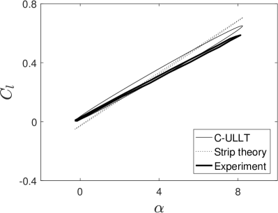
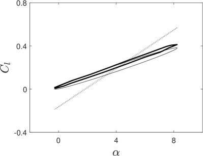
The ULLTs assume a zero average pitch angle. To model a non-zero average, the results of the ULLT are summed with the steady results of Prandtl’s lifting-line theory Prandtl1923 . This is consistent because both theories are linear. Variation of sectional lift coefficient () with angle of attack, at different locations over the wing span, from C-ULLT (with steady solution added) and experiment are compared in figure 11.
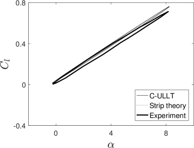
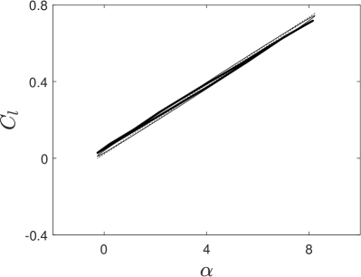
The experimental data has both the largest amplitude and the highest average (compared to itself) nearest to the center of the wing at as shown in figure 11(a). There is a small phase difference between the angle of attack and lift coefficient, resulting in an elliptic curve. At , shown in figure 11(b), the amplitude of remains similar, although the less elliptical curves suggests that the loads are now more closely in phase to the kinematics.
Closer to the tip at , the amplitude of the obtained by the experiment is reduced. Figure 11(d) shows the result very to the wing tip at . Both average and amplitude are further reduced in comparison to the inboard result. The curve obtained in noticeably non-smooth. These results agree with the distribution of obtained using CFD for lower aspect ratios. Namely, that the amplitude decreases near the wing tips.
Near the center of the wing at and (figures 11(a) and 11(b)), the match between theory (ULLT) and experiment is very good. Strip theory, shown for comparison, also provides very good agreement with CFD at these spanwise locations. This is in line with expectations for very high aspect ratio wings ( in this case), where the behavior near the root would be nearly 2D.
Moving towards the tip, the improvement offered by ULLT over strip theory is clear. The ULLT/LLT slightly over-predicts both the mean and amplitude of at , shown in figure 11(c), and also suggests a larger phase difference between the kinematics and loads than experiment. At , the ULLT/LLT under-predicts . However, at both these spanwise locations near the wing tip, ULLT provides a much better prediction than strip theory.
5 Conclusions
In this paper, three unsteady lifting-line theories (ULLTs) have been obtained from a common framework: a ‘complete’ ULLT contains corrections for both components of vorticity in the outer domain, a novel simplified version that considers only the streamwise component, and a pseudosteady, Prandtl-like ULLT.
These ULLTs were systematically compared both against each other and against Euler CFD results for various aspect ratio rectangular wings at various oscillation frequencies. The ULLTs were capable of capturing trends in wing lift coefficient with respect to both oscillation frequency and aspect ratio, always providing better results than 2D strip theory. They were also able to capture the changes in lift distribution across the wing with respect to frequency, despite being less accurate close to the wing tips. For aeroelastic analysis, this provides advantages over assumed lift-distribution models unable to account for changes in oscillation frequency.
Comparing between the three ULLTs, it was found that in regimes where ULLT assumptions are best satisfied (high aspect ratio and low reduced frequency), the complete ULLT is most accurate. At high frequencies of motion, the Prandtl-like pseudosteady ULLT provided the best prediction, although this may be luck specific to the rectangular wings studied.
By modifying the wake model, the computational cost could be reduced at the expense of reduced accuracy. The novel ULLT considering only the streamwise component of the vorticity in the outer domain was found to provide an excellent reduction in computational cost with minimal loss in accuracy. The pseudosteady ULLT reduced computational cost further still, but provided worse accuracy at low frequencies.
ULLT was also compared against experimental data, confirming that it is not only applicable to Euler/inviscid problems, but also to practical high Reynolds number flows.
The results obtained in this paper are important because they show how ULLT provides a low computational cost model capable of accounting for the interacting 3D aerodynamic effects of aspect ratio and oscillation frequency. The simplified wake models provide not only a means by which accuracy can be traded for reductions in computational cost, but also guidance on the construction of numerical and time-domain ULLTs. In particular, the streamwise vorticity ULLT demonstrates how an entire component of outer solution wake vorticity can be neglected (along with its self-canceling singularities), with only a small cost to the accuracy of the solution.
6 Acknowledgments
The authors gratefully acknowledge the support of the UK Engineering and Physical Sciences Research Council (EPSRC) through a DTA scholarship and grant EP/R008035. The Cirrus UK National Tier-2 HPC service at EPCC (http://www.cirrus.ac.uk) and the ARCHIE-WeSt High Performance Computer (www.archie-west.ac.uk) based at the University of Strathclyde were used in CFD simulations. We’d also like to thank the reviewers of this paper for their insightful feedback.
Data Availability
The datasets generated during and/or analysed during the current study are available from the corresponding author on reasonable request.
References
- (1) Ahmadi, A.R., Widnall, S.E.: Unsteady lifting-line theory as a singular perturbation problem. Journal of Fluid Mechanics 153, 59 (1985). DOI 10.1017/s0022112085001148
- (2) Andreu Angulo, I., Ansell, P.J.: Influence of aspect ratio on dynamic stall of a finite wing. AIAA journal pp. 2722–2733 (2019)
- (3) Beals, N., Jones, A.R.: Lift production by a passively flexible rotating wing. AIAA Journal 53(10), 2995–3005 (2015)
- (4) Biler, H., Badrya, C., Jones, A.R.: Experimental and computational investigation of transverse gust encounters. AIAA Journal 57(11), 4608–4622 (2019)
- (5) Bird, H.J.A., Otomo, S., Ramesh, K., Viola, I.M.: A geometrically non-linear time-domain unsteady lifting-line theory. In: AIAA Scitech 2019 Forum. American Institute of Aeronautics and Astronautics (2019). DOI 10.2514/6.2019-1377
- (6) Bird, H.J.A., Ramesh, K.: Theoretical and computational studies of a rectangular finite wing oscillating in pitch and heave. Proceedings of the 6th. European Conference on Computational Mechanics (ECCM 6) and the 7th. European Conference on Computational Fluid Dynamics (ECFD 7) pp. 3944–3955 (2018)
- (7) Boutet, J., Dimitriadis, G.: Unsteady lifting line theory using the wagner function for the aerodynamic and aeroelastic modeling of 3d wings. Aerospace 5(3), 92 (2018). DOI 10.3390/aerospace5030092
- (8) Calderon, D., Cleaver, D., Gursul, I., Wang, Z.: On the absence of asymmetric wakes for periodically plunging finite wings. Physics of Fluids 26(7), 349–376 (2014)
- (9) Calderon, D., Wang, Z., Gursul, I.: Lift-enhancing vortex flows generated by plunging rectangular wings with small amplitude. AIAA journal 51(12), 2953–2964 (2013)
- (10) Calderon, D.E., Wang, Z., Gursul, I., Visbal, M.: Volumetric measurements and simulations of the vortex structures generated by low aspect ratio plunging wings. Physics of Fluids 25(6), 067,102 (2013)
- (11) Caprace, D.G., Winckelmans, G., Chatelain, P.: An immersed lifting and dragging line model for the vortex particle-mesh method. Theoretical and Computational Fluid Dynamics (2020)
- (12) Carr, L.: Progress in analysis and prediction of dynamic stall. Journal of Aircraft 25(1), 6–17 (1988)
- (13) Carr, L.W., Platzer, M.F., Chandrasekhara, M.S., Ekaterinaris, J.: Experimental and computational studies of dynamic stall. In: T. Cebeci (ed.) Numerical and Physical Aspects of Aerodynamic Flows IV, pp. 239–256. Springer Berlin Heidelberg (1990)
- (14) Carr, Z.R., Chen, C., Ringuette, M.J.: Finite-span rotating wings: three-dimensional vortex formation and variations with aspect ratio. Experiments in fluids 54(2), 1–26 (2013)
- (15) Carr, Z.R., DeVoria, A.C., Ringuette, M.J.: Aspect-ratio effects on rotating wings: circulation and forces. Journal of Fluid Mechanics 767, 497–525 (2015)
- (16) Cheng, H.K.: On lifting-line theory in unsteady aerodynamics. Tech. Rep. 133, University of Southern California Los Angeles, Dept. of Aerospace Engineering (1976)
- (17) Corkery, S., Babinsky, H., Harvey, J.: On the development and early observations from a towing tank-based transverse wing–gust encounter test rig. Experiments in Fluids 59(9), 135 (2018)
- (18) Darakananda, D., Eldredge, J.D.: A versatile taxonomy of low-dimensional vortex models for unsteady aerodynamics. Journal of Fluid Mechanics 858, 917–948 (2018). DOI 10.1017/jfm.2018.792
- (19) Devinant, P.: An approach for unsteady lifting-line time-marching numerical computation. International Journal for Numerical Methods in Fluids 26(2), 177–197 (1998). DOI 10.1002/(sici)1097-0363(19980130)26:2¡177::aid-fld633¿3.3.co;2-g
- (20) DeVoria, A.C., Mohseni, K.: On the mechanism of high-incidence lift generation for steadily translating low-aspect-ratio wings. Journal of Fluid Mechanics 813, 110–126 (2017)
- (21) Ekaterinaris, J.A., Platzer, M.F.: Computational prediction of airfoil dynamic stall. Progress in aerospace sciences 33(11), 759–846 (1998)
- (22) Eldredge, J., Darakananda, D.: Reduced-order two- and three-dimensional vortex modeling of unsteady separated flows. In: 53rd AIAA Aerospace Sciences Meeting. American Institute of Aeronautics and Astronautics (2015). DOI 10.2514/6.2015-1749
- (23) Fishman, G., Wolfinger, M., Rockwell, D.: The structure of a trailing vortex from a perturbed wing. Journal of Fluid Mechanics 824, 701–721 (2017)
- (24) Gallay, S., Laurendeau, E.: Nonlinear generalized lifting-line coupling algorithms for pre/poststall flows. AIAA Journal 53(7), 1784–1792 (2015). DOI 10.2514/1.j053530
- (25) Garrick, I.E.: On some reciprocal relations in the theory of nonstationary flows. Tech. rep., NACA (1938)
- (26) Green, M.A., Rowley, C.W., Smits, A.J.: The unsteady three-dimensional wake produced by a trapezoidal pitching panel. Journal of Fluid Mechanics 685, 117–145 (2011)
- (27) Guermond, J.L.: A generalized lifting-line theory for curved and swept wings. Journal of Fluid Mechanics 211(-1), 497 (1990). DOI 10.1017/s0022112090001665
- (28) Guermond, J.L., Sellier, A.: A unified unsteady lifting-line theory. Journal of Fluid Mechanics 229, 427 (1991). DOI 10.1017/s0022112091003099
- (29) Hansen, M., Sørensen, J., Voutsinas, S., Sørensen, N., Madsen, H.: State of the art in wind turbine aerodynamics and aeroelasticity. Progress in Aerospace Sciences 42(4), 285–330 (2006). DOI 10.1016/j.paerosci.2006.10.002
- (30) Hirato, Y., Shen, M., Gopalarathnam, A., Edwards, J.R.: Vortex-sheet representation of leading-edge vortex shedding from finite wings. Journal of Aircraft pp. 1–15 (2019)
- (31) Holten, T.V.: Some notes on unsteady lifting-line theory. Journal of Fluid Mechanics 77(03), 561 (1976). DOI 10.1017/s0022112076002255
- (32) Hord, K., Lian, Y.: Leading edge vortex circulation development on finite aspect ratio pitch-up wings. AIAA Journal pp. 2755–2767 (2016)
- (33) James, E.C.: Lifting-line theory for an unsteady wing as a singular perturbation problem. Journal of Fluid Mechanics 70(04), 753 (1975). DOI 10.1017/s0022112075002339
- (34) Jantzen, R.T., Taira, K., Granlund, K., Ol, M.V.: Vortex dynamics around pitching plates. Physics of Fluids 26(5), 053,606 (2014)
- (35) Jones, R.T.: The unsteady lift of a finite wing. Tech. rep., National advisory committee for aeronautics (1939)
- (36) Katz, J., Plotkin, A.: Low Speed Aerodynamics, 2 edn. Cambridge University Press (2001)
- (37) Leishman, G.J.: Principles of Helicopter Aerodynamics. Cambridge University Press (2006)
- (38) Mancini, P., Manar, F., Granlund, K., Ol, M.V., Jones, A.R.: Unsteady aerodynamic characteristics of a translating rigid wing at low Reynolds number. Physics of Fluids 27(12), 123,102 (2015)
- (39) McCroskey, W.J.: The Phenomenon of Dynamic Stall. NASA TM 81264 (1981)
- (40) McGowan, G.Z., Granlund, K., Ol, M.V., Gopalarathnam, A., Edwards, J.R.: Investigations of lift-based pitch-plunge equivalence for airfoils at low Reynolds numbers. AIAA Journal 49(7), 1511–1524 (2011)
- (41) Medina, A., Jones, A.R.: Leading-edge vortex burst on a low-aspect-ratio rotating flat plate. Physical Review Fluids 1(4), 044,501 (2016)
- (42) Moored, K.W.: Unsteady three-dimensional boundary element method for self-propelled bio-inspired locomotion. Computers & Fluids 167, 324–340 (2018)
- (43) Mulleners, K., Mancini, P., Jones, A.R.: Flow development on a flat-plate wing subjected to a streamwise acceleration. AIAA Journal 55(6), 2118–2122 (2017)
- (44) Murua, J., Palacios, R., Graham, J.M.R.: Applications of the unsteady vortex-lattice method in aircraft aeroelasticity and flight dynamics. Progress in Aerospace Sciences 55, 46–72 (2012). DOI 10.1016/j.paerosci.2012.06.001
- (45) Ol, M.V., Bernal, L., Kang, C.K., Shyy, W.: Shallow and deep dynamic stall for flapping low Reynolds number airfoils. Experiments in Fluids 46(5), 883–901 (2009)
- (46) Olver, F.W., Lozier, D.W., Boisvert, R.F., Clark, C.W.: NIST Handbook of Mathematical Functions Paperback and CD-ROM. Cambridge University Press (2010)
- (47) Ozen, C.A., Rockwell, D.: Three-dimensional vortex structure on a rotating wing. Journal of Fluid Mechanics 707, 541–550 (2012)
- (48) Perrotta, G., Jones, A.R.: Unsteady forcing on a flat-plate wing in large transverse gusts. Experiments in Fluids 58(8), 101 (2017)
- (49) Piziali, R.A.: 2-d and 3-d oscillating wing aerodynamics for a range of angles of attack including stall. Tech. rep., NASA (1994). URL https://ntrs.nasa.gov/search.jsp?R=19950012704
- (50) Prandtl, L.: Applications of modern hydrodynamics to aeronautics. Tech. rep., NACA (1923). Rep. 116
- (51) Ramesh, K.: On the leading-edge suction and stagnation point location in unsteady flows past thin aerofoils. Journal of Fluid Mechanics 886(A13) (2020)
- (52) Ramesh, K., Gopalarathnam, A., Edwards, J.R., Ol, M.V., Granlund, K.: An unsteady airfoil theory applied to pitching motions validated against experiment and computation. Theoretical and Computational Fluid Dynamics 27(6), 843–864 (2013)
- (53) Ramesh, K., Gopalarathnam, A., Granlund, K., Ol, M.V., Edwards, J.R.: Discrete-vortex method with novel shedding criterion for unsteady airfoil flows with intermittent leading-edge vortex shedding. Journal of Fluid Mechanics 751, 500–538 (2014)
- (54) Ramesh, K., Monteiro, T.P., Silvestre, F.J., Bernardo, A., aes Neto, G., de Souza Siqueria Versiani, T., da Silva, R.G.A.: Experimental and numerical investigation of post-flutter limit cycle oscillations on a cantilevered flat plate. In: International Forum on Aeroelasticity and Structural Dynamics 2017 (2017). URL http://eprints.gla.ac.uk/154722/
- (55) Roesler, B.T., Epps, B.P.: Discretization requirements for vortex lattice methods to match unsteady aerodynamics theory. AIAA Journal 56(6), 2478–2483 (2018). DOI 10.2514/1.j056400
- (56) Rostami, A.B., Armandei, M.: Renewable energy harvesting by vortex-induced motions: Review and benchmarking of technologies. Renewable and Sustainable Energy Reviews 70, 193–214 (2017). DOI 10.1016/j.rser.2016.11.202
- (57) Sclavounos, P.D.: An unsteady lifting-line theory. Journal of Engineering Mathematics 21(3), 201–226 (1987). DOI 10.1007/bf00127464
- (58) Smyth, A.S., Young, A.M., Mare, L.D.: The effect of 3D geometry on unsteady gust response, using a vortex lattice model. In: AIAA Scitech 2019 Forum. American Institute of Aeronautics and Astronautics (2019). DOI 10.2514/6.2019-0899
- (59) Sugar-Gabor, O.: A general numerical unsteady non-linear lifting line model for engineering aerodynamics studies. The Aeronautical Journal 122(1254), 1199–1228 (2018). DOI 10.1017/aer.2018.57
- (60) Theodorsen, T.: General theory of aerodynamic instability and the mechanism of flutter. Tech. Rep. 496, NACA (1935)
- (61) Van Dyke, M.: Lifting-line theory as a singular-perturbation problem. Journal of Applied Mathematics and Mechanics 28(1), 90–102 (1964). DOI 10.1016/0021-8928(64)90134-0
- (62) Venkata, S.K., Jones, A.R.: Leading-edge vortex structure over multiple revolutions of a rotating wing. Journal of aircraft 50(4), 1312–1316 (2013)
- (63) Visbal, M.R.: Unsteady flow structure and loading of a pitching low-aspect-ratio wing. Physical Review Fluids 2(2), 024,703 (2017)
- (64) Visbal, M.R., Garmann, D.J.: Dynamic stall of a finite-aspect-ratio wing. AIAA Journal 57(3), 962–977 (2019)
- (65) Visbal, M.R., Garmann, D.J.: Effect of sweep on dynamic stall of a pitching finite-aspect-ratio wing. AIAA Journal 57(8), 3274–3289 (2019)
- (66) Visbal, M.R., Yilmaz, T.O., Rockwell, D.: Three-dimensional vortex formation on a heaving low-aspect-ratio wing: computations and experiments. Journal of Fluids and Structures 38, 58–76 (2013)
- (67) Wagner, H.: Über die entstehung des dynamischen auftriebes von tragflügeln. ZAMM - Zeitschrift für Angewandte Mathematik und Mechanik 5(1), 17–35 (1925). DOI 10.1002/zamm.19250050103
- (68) Wang, Z., Chen, P.C., Liu, D.D., Mook, D.T.: Nonlinear-aerodynamics/nonlinear-structure interaction methodology for a high-altitude long-endurance wing. Journal of Aircraft 47(2), 556–566 (2010). DOI 10.2514/1.45694
- (69) Willis, D.J., Peraire, J., White, J.K.: A combined pfft-multipole tree code, unsteady panel method with vortex particle wakes. International Journal for Numerical Methods in Fluids 53(8), 1399–1422 (2007)
- (70) Yilmaz, T., Ol, M., Rockwell, D.: Scaling of flow separation on a pitching low aspect ratio plate. Journal of Fluids and Structures 26(6), 1034–1041 (2010)
- (71) Yilmaz, T.O., Rockwell, D.: Three-dimensional flow structure on a maneuvering wing. Experiments in Fluids 48(3), 539–544 (2010)
- (72) Yilmaz, T.O., Rockwell, D.: Flow structure on finite-span wings due to pitch-up motion. Journal of Fluid Mechanics 691, 518–545 (2012)