FPGA Implementations of Layered MinSum LDPC Decoders Using RCQ Message Passing
Abstract
Non-uniform message quantization techniques such as reconstruction-computation-quantization (RCQ) improve error-correction performance and decrease hardware complexity of low-density parity-check (LDPC) decoders that use a flooding schedule. Layered MinSum RCQ (L-msRCQ) enables message quantization to be utilized for layered decoders and irregular LDPC codes. We investigate field-programmable gate array (FPGA) implementations of L-msRCQ decoders. Three design methods for message quantization are presented, which we name the Lookup, Broadcast, and Dribble methods. The decoding performance and hardware complexity of these schemes are compared to a layered offset MinSum (OMS) decoder. Simulation results on a (16384, 8192) protograph-based raptor-like (PBRL) LDPC code show that a 4-bit L-msRCQ decoder using the Broadcast method can achieve a 0.03 dB improvement in error-correction performance while using 12% fewer registers than the OMS decoder. A Broadcast-based 3-bit L-msRCQ decoder uses 15% fewer lookup tables, 18% fewer registers, and 13% fewer routed nets than the OMS decoder, but results in a 0.09 dB loss in performance.
Index Terms:
LDPC, RCQ, FPGA, layered decoding, low bit width decoder, PBRL.I Introduction
Low-density parity-check (LDPC) codes are powerful error-correcting codes that approach channel capacity when high-precision message passing is used while decoding. Realistic hardware implementations of LDPC decoders limit the width of the messages passed between variable nodes (VNs) and check nodes (CNs). This sacrifices error-rate performance to achieve lower resource utilization and wiring complexity. Uniformly quantized messages typically range from 5-7 bits, with anything less resulting in a sizable reduction in error-correction ability [1, 2].
A significant amount of research has been put into reducing message widths to less than 5 bits. Non-uniform quantization schemes, which effectively extend the dynamic range of the quantizers, use only 3 or 4 bits to achieve similar or even better performance than full-precision belief propagation (BP) and MinSum decoding [3, 4, 5, 6, 7, 8, 9, 10]. J. K. Lee et al. propose the mutual information maximization quantized belief propagation (MIM-QBP)[8] decoder, which designs iteration-specific non-uniform quantizers and reconstruction mappings at nodes. Both VN and CN operations are simple mappings and fixed point additions for MIM-QBP. X. He in [9] shows how to systematically design the parameters for quantization and reconstruction modules. L. Wang et al. further generalize the MIM-QBP structure and propose a reconstruction-computation-quantization (RCQ) paradigm [10] which allows CNs to use the Min operation for computation reduction.
Existing works on non-uniform quantization decoders have typically focused on regular LDPC codes, which are convenient for hardware decoders due to the uniformity of the VN and CN degrees[6, 7, 8, 9]. Some attention has been given to irregular codes, which have better error-rate performance, but present challenges with message quantization and hardware design due to the varying node degrees [4, 5, 3, 10, 11]. Additionally, a fully parallel or flooding schedule for CN operations and VN updates is generally assumed [8, 9, 6, 7, 4]. This approach may be undesirable or even unfeasible for decoder implementations using codes with large block lengths, where the design of a fully parallel decoder becomes very resource intensive. Instead, a partially parallel or layered architecture is often preferred [12].
I-A Contributions
As a primary contribution, we investigate field-programmable gate array (FPGA) implementations of a layered MinSum RCQ (L-msRCQ) decoder for irregular LDPC codes. Three design methods are presented in this paper:
-
•
Lookup method: all L-msRCQ parameters are stored in local read-only memories (ROMs) in VNs. Reconstruction and quantization are performed as ROM lookups.
-
•
Broadcast method: L-msRCQ parameters are stored in a centralized ROM and broadcasted to VNs. Quantization and reconstruction are performed using small lookup tables (LUTs) as logic.
-
•
Dribble method: the current layer’s L-msRCQ parameters are stored locally at VNs in registers, quantization and reconstruction are performed using LUTs as logic.
We use these methods to design 3-bit and 4-bit L-msRCQ decoders for a quasi-cyclic (QC) protograph-based raptor-like (PBRL) LDPC code[13] with code length 16384 and rate . The decoding performance and hardware complexity of these three methods are analyzed. As a reference, a series of layered offset MinSum (OMS) decoders using uniform message quantization of 5-7 bits are provided. Simulation and hardware utilization results show that the 4-bit L-msRCQ decoder using the Broadcast method can achieve a 0.03 dB increase in error-correction performance and a 12% decrease in register usage compared to the OMS reference decoder. A 3-bit Broadcast-based L-msRCQ decoder results in a 0.09 dB loss in performance, but requires 15% fewer LUTs, 18% fewer registers, and 13% fewer routed nets than the OMS decoder.
I-B Outline
The remainder of this paper is organized as follows. Section II provides background on layered MinSum decoding, OMS decoding, and RCQ. Section III presents the reference OMS decoder architecture. Section IV describes the Lookup, Broadcast, and Dribble methods used for the L-msRCQ implementations. Section V presents the frame error rate (FER) performance and resource utilization of each decoding scheme.
II Background
An LDPC code is defined by a sparse parity check matrix , where is the number of CNs and is the number of VNs. Let denote the set of VNs that connect to CN , let represent the set of CNs that connect to VN , and let stand for the decoding iteration. We define the following notations:
-
•
: the log-likelihood ratio (LLR) for variable derived from the channel output.
-
•
: the LLR message passed from CN to VN .
-
•
: the LLR message passed from VN to CN .
-
•
: the a posteriori LLR (AP-LLR) of variable .
II-A Layered MinSum and Offset MinSum Decoding
The MinSum and OMS algorithms for LDPC decoding are approximations of the BP algorithm, offering simplified CN operations at a small performance loss [14, 15]. A horizontal layered decoding approach processes sets of CNs sequentially, enabling better code performance compared to a flooding approach with respect to iterations required, while using less hardware resources [16]. We consider decoding iterations . To begin a decoding iteration, the AP-LLRs are initialized:
| (1) |
A VN-to-CN message is calculated:
| (2) |
For the MinSum algorithm, CN-to-VN messages are obtained:
| (3) |
The OMS algorithm subtracts a small positive constant from the CN-to-VN messages for a better approximation of BP:
| (4) | ||||
The AP-LLRs are updated:
| (5) |
Decoding terminates after the syndrome check is passed or iterations have taken place.
For hardware decoder implementations using message quantization, the bit widths of the VN-to-CN messages calculated in Eq.(2) are reduced. We refer to the quantized values as . The CN operations in Eq.(3) or Eq.(4) operate on these reduced precision values to calculate the quantized CN-to-VN messages . In this paper, we use the pair to describe a decoder’s bit width, where denotes the bit width for CN operations and represents the bit width for .
QC-LDPC codes are a family of structured LDPC codes characterized by a parity check matrix which consists of square sub-matrices that are either the zero matrix or cyclic permutations of the identity matrix (also called a circulant). By grouping CNs that form a row of circulants into a layer, each variable connects to at most one CN per layer. This allows the VN-to-CN message calculations and VN update rules from Eq.(2) and Eq.(5) to be applied to all the CNs and associated VNs in a layer at once, without needing to account for the same VN being updated multiple times. As a result, a total of CNs can be processed at once, achieving an excellent balance between decoder throughput and hardware complexity.
II-B Reconstruction-Computation-Quantization Decoder
An RCQ decoder allows for a low bit width representation of and by setting dynamic quantization and reconstruction mappings. The quantizers compress a -bit message to a -bit message , and reconstructions map a -bit message to a -bit message . The superscripts , represent the iteration number and layer index. More details on RCQ parameters are seen in [10]. In this work, we are focused on the L-msRCQ decoder, where layers are processed sequentially and Eq.(3) is performed at the CNs. We refer to L-msRCQ and RCQ interchangeably for the remainder of this paper.
III OMS Decoder Architecture
This section presents our FPGA design for the layered OMS decoder, which can be extended to implement the L-msRCQ decoder. The structure of our layered OMS decoder can be broken into three main components: VN banks, a CN pipeline, and a control unit. The architecture is largely governed by the construction of the chosen LDPC code. Since the parity matrix for a QC-LDPC code has an QC structure, the CN pipeline must be able to process the operations for CNs in parallel. Additionally, a total of VN banks are necessary, each able to send and receive one message from the CN pipeline per cycle.
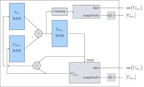
III-A VN Bank
The structure of a VN bank is shown in Fig. 1. A single VN bank is responsible for variables. VN bank contains variables . This ensures that variables which share the same circulants of the parity matrix are partitioned to different VN banks. Messages from all the variables in a circulant can be simultaneously sent and received by the total VN banks and the CN pipeline.
The RAM, RAM, and RAM in Fig. 1. each allow for one read and one write per cycle. To calculate , the required values from the RAM and RAM can be read out and subtracted. This result is sent to the CN pipeline and temporarily stored in the RAM. is clipped to a -bits message before being forwarded to the CN pipeline:
| (6) |
The sign and magnitude of are sent to the CN pipeline separately. Note that and are not included in the OMS decoder.
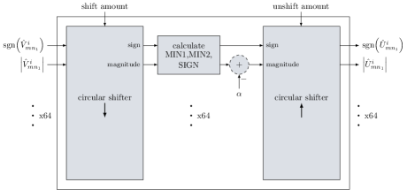
III-B CN pipeline
To process a layer, the VN-to-CN messages for every non-zero circulant in the layer are sequentially calculated and sent to the CN pipeline. The structure of the CN pipeline is shown in Fig. 2. The CN pipeline receives messages per cycle from the VN banks. Circular shifters align each wave of incoming messages with the CNs they contribute to. For a circulant in the parity matrix that is the identity matrix cyclically permuted by , its total VN-to-CN messages will be circularly shifted by so that the messages contribute to the correct CNs. The aligned values are fed into logic which calculates the first minimum (MIN1) magnitude and second minimum (MIN2) magnitude of the input messages, along with an XOR of all the sign bits (SIGN).
CN-to-VN messages are sequentially returned to the VN banks for each of the layer’s non-zero circulants. Along with the SIGN, the MIN1 or MIN2 value of a CN is sent back to its corresponding variables, depending on whether a VN provided the MIN1 value. An offset is subtracted from the selected MIN1 or MIN2 value. Circular shifters realign the MIN1 or MIN2 and SIGN values with the correct VN banks.
Each VN bank receives a sequence of CN-to-VN messages as sign and magnitudes values. When a message arrives, the corresponding message for the variable is read from the RAM. The sign bit of is XORed with the incoming sign value, and the result is used to calculate the signed CN-to-VN message . The result is stored in the RAM, and it is summed with to form an updated AP-LLR which is stored in the RAM. To allow the AP-LLR values to grow, the RAM stores bits.
III-C Control Unit
The control signals that dictate the logic of the VN banks and CN pipeline are provided by the control unit. A state machine manages the readout of values from VN bank RAMs, the shift amounts for the CN pipeline, and the writing of results back into the VN bank RAMs. To allow for a high decoder throughput, the described datapath is pipelined into multiple stages to enable a high frequency clock. The control unit overlaps the processing of adjacent layers, meaning that after the data for layer has been read out from the VN banks and sent to the CN pipeline, the values for layer are immediately read out before the writeback of layer completes. This allows for high utilization of the datapath pipeline, but creates read after write (RAW) hazards for VNs that are contained in consecutive layers, since the updated AP-LLR for a variable may not be written by the time it needs to be read out by the next layer. To overcome this, the sequential order in which the control unit reads circulants out of the VN banks has been hand modified so that VNs which encounter RAW hazards are read earlier or later in their layer’s sequence to prevent overlap from occurring.
IV L-msRCQ Decoder Architecture
The L-msRCQ decoder FPGA design expands on the design of the layered OMS decoder. The key differences between the L-msRCQ and layered OMS decoders are:
-
•
The L-msRCQ decoder requires the and functions in Fig. 1 to quantize and reconstruct message magnitudes.
-
•
Because the MinSum algorithm is used for CN operations, the offset calculation in Fig. 2 is not included in the CN pipeline.
To implement the quantization and reconstruction operations in the VN banks, we have devised the Lookup, Broadcast, and Dribble methods. These three approaches are functionally identical, but the way in which they compute the and operations differ, resulting in unique hardware utilizations.
IV-A Lookup Method
Since the quantization and reconstruction functions simply map an input message to an output message, an implementation based on a lookup into a ROM is evident. To quantize , the three-tuple is used to index into a ROM to obtain . Similarly for , the three-tuple forms an address to index into a ROM to read out . These and functions in every VN bank require their own ROMs, implemented using block RAMS (BRAMs). Assuming one BRAM is used for and one is used for , then VN banks with two ROMs each results in a total of additional BRAMs used. If BRAMs with multiple ports are available, then they can be shared by different VN banks to reduce the total amount required.
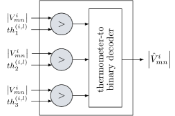
IV-B Broadcast Method
The Broadcast method provides a scheme where L-msRCQ parameters are centralized, instead of being stored in each VN bank. The pair is used to index into ROMs in the control unit. These ROMs output quantization thresholds and reconstruction values , which are wired to the VN banks. The and blocks in the VN banks take in the parameters and use logic to perform their respective operations. Fig. 3 shows an implementation for a 3-bit L-msRCQ, which uses a mere 2 bits for quantized message magnitudes. Two BRAMS are required in the control unit for the quantization thresholds and reconstruction values. Logic implemented using small LUTs is needed in the VN units because of the and functions. The main penalty comes with the wiring necessary to route the L-msRCQ parameters from the control unit to VN banks. As shown in Fig. 3, if bits are used for each of the thresholds and reconstruction values of 3-bit L-msRCQ, a total of additional wires need to be routed to a VN bank. With VN banks, the total amount of added routes increases by . For a 4-bit L-msRCQ decoder, the total increase is . It is to be noted that the same parameters are routed to all the VN banks, meaning that the required wiring can be reduce by path sharing.

IV-C Dribble Method
The Dribble method attempts to reduce the number of long wires required by the Broadcast method to send L-msRCQ parameters from the control unit to the VN banks. Registers in the VN banks save the current thresholds and reconstruction values necessary for the and functions. Once again, quantization and reconstruction can be implemented using the logic in Fig. 3. When a new set of parameters is required, the bits are transferred one by one or in small batches from the control unit to the VN bank registers. Just as in the Broadcast method, two extra BRAMs and logic for the and functions are required. But where the Broadcast method needs additional wires routed to each VN bank for 3-bit L-msRCQ, the Dribble method requires only as many wires as the transfer batch size. The penalty of the Dribble method comes with the extra usage of registers in the VN banks. A total of bits stored in registers would be necessary in each VN bank to save the current threshold and reconstruction values for 3-bit L-msRCQ. In total, bits of register storage would be used for 3-bit L-msRCQ, and bits would be necessary for 4-bit L-msRCQ. This total can be reduced by having multiple VN banks share sets of registers.
V FER and Resource Utilization Results
To test the OMS decoder and the Lookup, Broadcast, and Dribble L-msRCQ methodologies, the designs have been implemented on the programmable logic of a Xilinx Zynq UltraScale+ MPSoC device. Each design met timing with a 500 MHz clock. The maximum decoding iterations, , is set to 16, and for the OMS decoders we set .
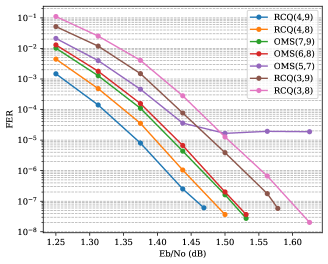
V-A FER Performance
The FER performance for the decoder configurations at varying is shown in Fig. 4. The bit width of each decoder is specified by its pair. The RCQ(4,9) and RCQ(4,8) designs show a 0.05 and 0.03 dB improvement in FER performance respectively compared to the OMS(6,8) decoder at FER . Meanwhile, the RCQ(3,9) and RCQ(3,8) designs show a 0.06 and 0.09 dB decrease in FER performance respectively compared to OMS(6,8) at FER , while avoiding the error floor above FER faced by the OMS(5,7) decoder. The OMS(7,9) and OMS(6,8) decoder performances are nearly identical.
V-B LUTs and Registers
The LUT and register usage of the investigated decoders is shown in Fig. 5a. The 3-bit L-msRCQ decoders show a decrease in LUT and register usage compared to the OMS(6,8) decoder due to fewer bits being used in the CN pipeline. For the 4-bit L-msRCQ decoders, register usage decreases, but LUT count increases for the non-Lookup decoding schemes due to the logic necessary for the and functions. Dribble-based decoders do not exhibit the expected penalty of increased register utilization, since the synthesis tool recognizes and removes the redundant registers held in different VN banks. To meet more stringent timing constraints, more of these redundant registers can be left present in the design to allow for better localization of L-msRCQ parameters to and logic.
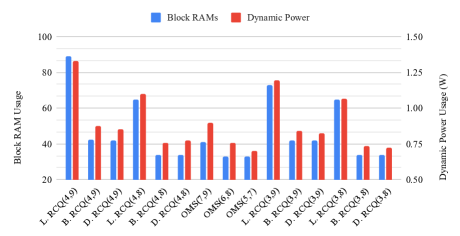
V-C BRAMs and Dynamic Power
Fig.5b shows the BRAM usage and power consumption of each decoder. Power consumption is measured using the Xilinx Vivado Design Suite’s power estimation capabilities. Since the static power usage of all the designs is 0.597, we compare the dynamic power consumption. The large amount of L-msRCQ data storage in VN banks for the Lookup-based decoders requires these designs to use by far the most BRAMs. Additionally, designs using bits for require more BRAMs as compared to the designs using only bits. Fig.5b reveals that large BRAM usage induces a large power consumption.

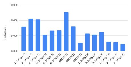
V-D Routed Nets
To understand the wiring cost of the L-msRCQ designs, Fig. 5c shows the number of routed nets in each architecture. A reduced message size and fewer bits being used in the CN pipeline decreases the number of routes for the 3-bit L-msRCQ designs and also in the RCQ(4,8) designs compared to OMS(6,8). The Broadcast-based L-msRCQ decoders do not experience the expected increase in routing resources used in order to wire and parameters to VN banks. This can be attributed to the decrease of routing elsewhere in the designs such as with message passing and CN operations, effectively offsetting the extra routes for the L-msRCQ data.
| decoder | Eb/Noa | LUT | Reg. | BRAM | Rt. Net | Powerb |
| baselinec | 1.51 | 9484 | 9518 | 33 | 15201 | 0.757 |
| L. RCQ(4,9) | -0.05 | -11% | -3% | +170% | 0% | +75% |
| B. RCQ(4,9) | -0.05 | +10% | -4% | +29% | +7% | +15% |
| D. RCQ(4,9) | -0.05 | +12% | -4% | +27% | +6% | +13% |
| L. RCQ(4,8) | -0.03 | -16% | -10% | +97% | -7% | +45% |
| B. RCQ(4,8) | -0.03 | +1% | -12% | +3% | -3% | 0% |
| D. RCQ(4,8) | -0.03 | +2% | -11% | +3% | -3% | +2% |
| OMS(7,9) | 0 | +18% | +12% | +24% | +12% | +18% |
| OMS(6,8) | 0 | 0% | 0% | 0% | 0% | 0% |
| OMS(5,7) | N/A | -15% | -14% | 0% | -14% | -8% |
| L. RCQ(3,9) | +0.06 | -17% | -9% | +121% | -6% | +57% |
| B. RCQ(3,9) | +0.06 | -8% | -12% | +27% | -7% | +11% |
| D. RCQ(3,9) | +0.06 | -8% | -10% | +27% | -5% | +9% |
| L. RCQ(3,8) | +0.09 | -22% | -16% | +97% | -13% | +41% |
| B. RCQ(3,8) | +0.09 | -15% | -18% | +3% | -13% | -3% |
| D. RCQ(3,8) | +0.09 | -17% | -17% | +3% | -15% | -4% |
| aEstimated signal to noise ratio to achieve FER of | ||||||
| bDynamic power usage measured in watts. | ||||||
| cFER performance and resource usage of the OMS(6,8) decoder. | ||||||
V-E Overall Comparison
Table I summarizes the FER performance and resource utilization data of all the implemented decoders compared to the OMS(6,8) decoder, which we treat as a baseline. The OMS(5,7) decoder has an error floor above FER , which removes it from consideration as the reference. The OMS(7,9) decoder has an FER performance that is too similar to the OMS(6,8) decoder to justify its increased resource utilization.
The Table I comparisons confirm that the Lookup-based L-msRCQ decoders require significantly more BRAMs and dynamic power than the other L-msRCQ architectures. Since the Lookup method does not provide any other significant resource advantages, we remove it from consideration. The Broadcast and Dribble architectures provide very similar utilizations for every considered resource. We focus on the Broadcast method in the following analysis due to its simplicity.
The best FER performance is provided by the highest-precision RCQ(4,9) decoders, which perform 0.05 dB better than the baseline OMS(6,8) decoder at FER . This performance is costly, using 29% more BRAMS and 15% more dynamic power for the Broadcast-based implementation. The Broadcast RCQ(4,8) decoder performs 0.03 dB better than the OMS(6,8) decoder while using 12% fewer registers than the baseline system and having an otherwise similar resource utilization. The Broadcast RCQ(3,9) decoder performs 0.06 dB worse than the OMS(6,8) decoder at FER and requires 27% more BRAMS and 11% more power, but uses 12% fewer registers. The Broadcast RCQ(3,8) structure performs 0.9 dB worse than the OMS(6,8) decoder, but uses 15% fewer LUTs, 18% fewer registers, and 13% fewer routed nets while requiring very similar amounts of BRAMs and power.
In summary, L-msRCQ with 8 bits used for VN bank storage is the more preferable architecture. With 4-bit messages and a Broadcast implementation, this architecture provides a slightly better FER than the baseline, while using fewer registers. With 3-bit messages and a Broadcast approach, the FER is slightly worse than OMS(6,8) but allows significant resource reductions in LUTs, registers, and routed nets.
VI Conclusion
In this paper, we investigate the FPGA implementations for a L-msRCQ decoding approach. Three L-msRCQ implementations are proposed in this paper: Lookup, Broadcast, and Dribble. We implemented a layered OMS decoder as a reference and multiple L-msRCQ decoders for a (16384,8192) PBRL code. Simulation results show that with 4-bit messages and a Broadcast implementation, L-msRCQ provides 0.03 dB better FER performance than our baseline OMS decoder and uses 12% fewer registers. With a Broadcast 3-bit L-msRCQ approach, a 0.09 dB performance loss is experienced, but the design uses 15% fewer LUTs, 18% fewer registers, and 13% fewer routed nets than the OMS decoder.
References
- [1] Jinghu Chen, A. Dholakia, E. Eleftheriou, M. P. C. Fossorier, and Xiao-Yu Hu, “Reduced-complexity decoding of LDPC codes,” IEEE Trans. Commun., vol. 53, no. 8, pp. 1288–1299, Aug. 2005.
- [2] Z. Zhang, L. Dolecek, M. Wainwright, V. Anantharam, and B. Nikolic, “Quantization effects in Low-Density Parity-Check decoders,” in 2007 IEEE International Conf. on Communications, Jun. 2007, pp. 6231–6237.
- [3] M. Stark, G. Bauch, L. Wang, and R. D. Wesel, “Information bottleneck decoding of rate-compatible 5g-ldpc codes,” ICC 2020 - 2020 IEEE International Conf. on Communications (ICC), pp. 1–6, 2020.
- [4] M. Meidlinger and G. Matz, “On irregular LDPC codes with quantized message passing decoding,” in 2017 IEEE 18th International Workshop on Signal Processing Advances in Wireless Communications (SPAWC), Jul. 2017, pp. 1–5.
- [5] M. Stark, J. Lewandowsky, and G. Bauch, “Information-Optimum LDPC decoders with message alignment for irregular codes,” in 2018 IEEE Global Communications Conf. (GLOBECOM), Dec. 2018, pp. 1–6.
- [6] J. Lewandowsky and G. Bauch, “Information-Optimum LDPC decoders based on the information bottleneck method,” IEEE Access, vol. 6, pp. 4054–4071, 2018.
- [7] F. J. C. Romero and B. M. Kurkoski, “LDPC decoding mappings that maximize mutual information,” IEEE J. Sel. Areas Commun., vol. 34, no. 9, pp. 2391–2401, Sep. 2016.
- [8] J. K. S. Lee and J. Thorpe, “Memory-efficient decoding of ldpc codes,” in Proceedings. International Symposium on Information Theory, 2005. ISIT 2005., 2005, pp. 459–463.
- [9] X. He, K. Cai, and Z. Mei, “On mutual Information-Maximizing quantized belief propagation decoding of LDPC codes,” in 2019 IEEE Global Communications Conf. (GLOBECOM), Dec. 2019, pp. 1–6.
- [10] L. Wang, R. D. Wesel, M. Stark, and G. Bauch, “A Reconstruction-Computation-Quantization (RCQ) approach to node operations in LDPC decoding,” in GLOBECOM 2020 - 2020 IEEE Global Communications Conf., Dec. 2020, pp. 1–6.
- [11] M. G. Luby, M. Mitzenmacher, M. A. Shokrollahi, and D. A. Spielman, “Improved low-density parity-check codes using irregular graphs,” IEEE Trans. Inf. Theory, vol. 47, no. 2, pp. 585–598, Feb. 2001.
- [12] Y. . Chang, A. I. V. Casado, M. . F. Chang, and R. D. Wesel, “Lower-Complexity layered Belief-Propagation decoding of LDPC codes,” in 2008 IEEE International Conf. on Communications, May 2008, pp. 1155–1160.
- [13] T. Chen, K. Vakilinia, D. Divsalar, and R. D. Wesel, “Protograph-Based Raptor-Like LDPC codes,” IEEE Trans. Commun., vol. 63, no. 5, pp. 1522–1532, May 2015.
- [14] M. P. C. Fossorier, M. Mihaljevic, and H. Imai, “Reduced complexity iterative decoding of low-density parity check codes based on belief propagation,” IEEE Trans. Commun., vol. 47, no. 5, pp. 673–680, May 1999.
- [15] J. Chen and M. P. C. Fossorier, “Density evolution for two improved BP-Based decoding algorithms of LDPC codes,” IEEE Commun. Lett., vol. 6, no. 5, pp. 208–210, May 2002.
- [16] D. E. Hocevar, “A reduced complexity decoder architecture via layered decoding of LDPC codes,” in IEEE Workshop onSignal Processing Systems, 2004. SIPS 2004., Oct. 2004, pp. 107–112.