Joint Beamforming Design for Multiuser MISO Downlink Aided by a Reconfigurable Intelligent Surface and a Relay ††thanks: Part of this work is accepted to be presented at the IEEE International Conference on Communications (ICC workshop) 2021 [1].
Abstract
Reconfigurable intelligent surfaces (RIS) have drawn considerable attention recently due to their controllable scattering elements that are able to direct electromagnetic waves into desirable directions. Although RISs share some similarities with relays, the two have fundamental differences impacting their performance. To harness the benefits of both relaying and RISs, a multi-user communication system is proposed in this paper wherein a relay and an RIS cooperate to improve performance in terms of energy efficiency. Using singular value decomposition (SVD), semidefinite programming (SDP), and function approximations, we propose different solutions for optimizing the beamforming matrices at the base-station (BS), the relay, and the phase shifts at the RIS to minimize the total transmit power subject to quality-of-service (QoS) constraints. The problem is solved in different cases when the relay operates in half-duplex and full-duplex modes and when the reflecting elements have continuous and discrete phase shifts. Simulation results are provided to compare the performance of the system with and without the RIS or the relay in both full-duplex and half-duplex modes, under different optimization solutions. Generally, the results show that the system with full-duplex relay and RIS cooperation outperforms all the other scenarios, and the contribution of full-duplex relay is higher than that of the RIS. However, an RIS performs better than a half-duplex relay when the required QoS is high. The results also show that increasing the number of RIS reflecting elements improves performance better in the presence of a relay than in its absence.
Index Terms:
Reconfigurable intelligent surfaces, intelligent reflecting surfaces, relaying, decode-and-forward, half-duplex, full-duplex.I Introduction
The performance of wireless communication systems is affected by wave propagation phenomena such as scattering, delays, reflections, and diffractions. Such phenomena makes the received signal consist of a superposition of multiple random, delayed, and attenuated copies of the transmitted signal, which impacts the achievable rate, energy efficiency, and coverage. Thus, adding some level of reconfigurability to the propagation medium can improve performance. Recently, a solution has been proposed to achieve this goal via deploying a reconfigurable intelligent surface (RIS), which is a two dimensional surface consisting of digitally-controllable reflecting elements [2, 3, 4].
The elements of an RIS can be controlled to achieve a specified objective such as strengthening the received signal or weakening the received interference. Specifically, the RIS elements can control the phase shifts between the incident and reflected waves so that the received waves add up constructively or destructively at a receiver. In addition to the ability of RISs to configure the radio environment, they have other desired properties such as: i) easy installation, ii) low cost, iii) passive elements, and iv) low energy consumption. In addition, RIS can perform its function without the need for sophisticated radio-frequency circuits and digital signal processing. All these features allow an RIS to realize a smart radio environment that can be programmed to improve customized objectives such as spectral efficiency, energy efficiency, secrecy capacity, and coverage probability. This gives RISs the potential to play a role in sixth generation (6G) wireless networks.
In the literature, several papers investigate how the RIS phase shifts can be optimized along with the beamforming vectors at the BS, with the goal of improving communication performance. For instance, an RIS can significantly improve the sum-rate in a multiple-input-multiple-output (MIMO) single user or multiuser system [5], increase the energy efficiency of the communication system [6, 7], decrease inter-cell interference [8], enhance the secrecy rate [9], maximize the minimum signal-to-interference and noise ratio (SINR) [10], and extend the coverage of millimetre wave communications [11]. Interestingly, as shown numerically in [12], the signal-to-noise ratio (SNR) of the RIS-assisted system with reflecting elements is improved by 10 dB compared to the non-RIS-assisted systems, and the SNR increases proportional to as increases. The authors in [13, 14] show that supporting wireless networks with RIS significantly contribute in improving the sum-rate even if the phase shifts of the reflecting elements are randomly selected.
Although RISs can be used to improve the end-to-end channel quality, their main limitation is that the magnitude of the reflected channel (base-station (BS) to RIS to user) is weak compared to the direct channel between the BS and the user, since this channel is the product of the BS-RIS channel and the RIS-user channel, and this phenomena is called the double fading effect. This limitation can be overcome if the RIS is replaced by a relay node (both of which share the forwarding functionality), at the expense of additional energy consumption and complexity at the relay. The authors in [15] compare RIS and relay-assisted systems and show that the RIS-assisted system is able to provide up to 300% higher energy efficiency compared to the use of a multi-antenna angular amplify-and-forward (AF) relaying system. This large gain is due to the fact that an RIS consumes very little power to forward the impinging signal contrary to a relay. However, the authors in [16] show that an RIS-assisted system cannot provide an SNR higher than that in a massive MIMO decode-and-forward (DF) relay-assisted system for any value of , again at the cost of more power consumption. This is due to fact that the end-to-end channel of the DF relay is much better than the reflected channel through the RIS. Authors of [17] discuss similarities and differences between RISs and relays, and argue that an RIS-assisted system outperforms a relay-assisted one in terms of data rates when the RIS is sufficiently large.
From the previous works, we can conclude that the RIS-assisted system performs better than the AF relay-assisted system, but worse than a DF relay-assisted one when the relay is equipped with a massive number of antennas. In general, each of the DF relay and the RIS have their own pros and cons in terms of energy efficiency, hardware and software complexity, range, etc., and it is interesting to combine the two in a system to harness both gains from the RIS and the DF relay. We note that while all the aforementioned papers consider a system with an RIS or a relay, but not both, [18, 19] study a system that consists of both an RIS and a relay. However, [18, 19] focus on a single-user system with a single-antenna transmitter and receiver and maximize the achievable rate. Since a multi-antenna multi-user system is more practical (and challenging), in this paper, we study a multi-user system employing a multi-antenna BS, a multi-antenna DF relay, and an RIS. Our goal is to optimize the parameters of the system (beamforming matrices and reflection phases) to improve the multi-user system energy efficiency.
I-A Contribution
The main contributions of the paper can be summarized as follows:
-
•
We describe transmissions schemes for a system consisting of a multi-antenna BS, a multi-antenna DF relay, an RIS, and multiple users, and we express the achievable rate of the schemes under both full-duplex and half-duplex relay operation.
-
•
We formulate optimization problems to minimize the total power under QoS constraints by jointly designing the beamforming matrices at the BS and the relay and the phase shifts at the RIS. We propose alternating optimization methods that solve for the beamforming parameters and the phase shifts iteratively. The problem is solved in different cases when the relay operates in half-duplex and full-duplex modes and when the reflecting elements have continuous and discrete phase shifts.
-
•
We compare the performance of the proposed system with system assisted by a relay-only and an RIS-only as benchmarks. We also study the impact of increasing the number of reflecting elements on performance, when a relay is present or absent.
I-B Discussion
To design the beamforming matrices, we first notice that the optimization of the BS and relay beamforming matrices is coupled in the formulated optimization problem. Thus, we first decouple these optimizations relying on the fact that the equivalent BS-user channels are much weaker than the equivalent relay-user channels. We then propose a solution using the singular value decomposition (SVD) and uplink-downlink duality approaches. For both full-duplex and half-duplex scenarios, we propose to place the RIS in the vicinity of the relay to enable better utilization of the reflecting elements in both hops (BS-to-relay and relay-to-users). This leads to optimize phase shifts in the half-duplex mode and phase shifts in the full-duplex mode. For optimizing the phase-shifts, we propose two solutions for each scenario (full and half-duplex) when the phase-shifts are continuous and two other solutions for the discrete phase shifts case. The solutions are based on SDP, signal energy maximization with fixed-point iteration, quantization, and successive refinement approach. Some of these approaches are proposed to achieve high performance and others to achieve low complexity.
We demonstrate numerically that the relay-RIS cooperation significantly reduces the required transmit power compared to the other systems. The results show that the contribution of the full-duplex relay in enhancing the performance is higher than that of the RIS, whose contribution in turn is better than the half-duplex relay when the required data rates (QoS) at the users is high. We also demonstrate numerically that increasing the number of reflecting elements has higher impact in the presence of a relay more than in its absence. In particular, increasing the number of reflecting elements from 20 to 180 reduces the required power by 0.28 dBm if there is no relay (RIS-only) and by 3.94 dBm if there is a full-duplex relay with 5 antennas (the proposed system). This means that the presence of a relay increases the effectiveness of RIS.
Next, we present the system model, describe the transmission scheme, and characterize the achievable rates. We optimize the half-duplex system in Sec. III and the full-duplex one in Section IV. Special cases and baseline approaches are provided in Section V. We provide numerical evaluations of the performance of the schemes in Sec. VI. Finally, we conclude in Sec. VII.
II System Model
We consider a downlink transmission system consisting of single-antenna users, a DF relay with antennas, a BS with antennas, and an RIS with elements (Fig. 1). The RIS is located near the relay to make it useful in both hops for reflecting signals from the BS to the relay and from the relay to the user. Moreover, the RIS and relay are assumed to be closer to the users than to the BS. We consider two cases where the relay either operates in a half-duplex or a full-duplex mode. In addition, we consider two cases for the RIS where the phase shifts are continuous or discrete.
The BS wants to transmit a message with rate (bits per symbol) to user for all . It encodes the messages into codewords of length symbols. The symbols follow a circularly symmetric complex Gaussian distribution with zero mean and unit variance. The BS then combines symbols from all codewords into a transmit signal which is sent to the relay and the users as described next for the half-duplex and full-duplex modes, in the next time slot if the relay is operated in a half-duplex mode, or in the same time slot if it is operated in a full-duplex mode. Next, we present the signal model and the achievable rates in half-duplex and full-duplex modes.
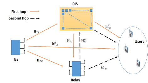
II-A Signal Model: Half-Duplex Mode
Here, we present the signal model and the achievable rates when the system works under the half-duplex constraint. Under such assumption, signals are transmitted in two phases. In phase 1, the BS sends messages intended to users encoded with rates to the relay, and the relay decodes these messages. In phase 2, the relay forwards the messages to the users, and the users combine the received signals from both phases and decode their desired messages. Note that due to this, although the encoding rate is (bit/symbol), the overall rate achieved by user is (bits per transmission) since each symbol is transmitted over two transmissions (phase 1 and phase 2). The role of the RIS is to reflect the transmitted signal from the transmitter to the relay and the users in the first phase, and from the relay to the users in the second phase.
The two phases of the transmission process, each of length symbols where is the codeword length, are explained next.
II-A1 Phase 1
In the first phase, the BS transmits a precoded signal that can be expressed as follows
| (1) |
where is the bemaforming vector assigned to user and is a symbol of the length- codeword to be sent to user . The symbols have unit power, and the transmit power of the BS in this phase is , where the is due to the half-duplex operation since the BS is active half of the time.
Each user receives a superposition of the transmitted signal through the direct links and the reflected links via RIS, given by
| (2) |
, where and are the channel coefficient from the BS to the RIS, and the BS to the user , respectively, is the channel vector from the RIS to the user , , is the phase shift of the th RIS element in the first phase, and is additive white Gaussian noise (AWGN) with zero mean and variance , independent through . The user will combine this signal with the received signal in the second phase before decoding.
The received signal at the relay in this phase is given by
| (3) |
, where , are the channel coefficient matrices from the BS to the relay and from the RIS to the relay, respectively, and is the AWGN vector at the relay with zero mean and covariance matrix , independent through .
The relay uses a decode-and-forward scheme. It decodes the users’ codewords from , , which imposes a rate constraint where
| (4) |
where and . After decoding, the relay knows for all and , which can be assumed error free if is large enough and is satisfied.
II-A2 Phase 2
After decoding, the relay multiplies the decoded codewords by vectors to beamform them to the RIS and the users. The relay sends leading to a transmit power .
The phase shifts at the RIS can be chosen to be different from the ones used in first phase. Therefore, the received signal at the user in this phase becomes
| (5) |
, where is the channel vector from the relay to the user , is the phase shift matrix in phase 2 with being the phase shift applied by the th RIS element, and is AWGN with zero mean and variance , independent through . Note that we assume channel reciprocity between the relay and the RIS, and hence the relay-RIS channel is the Hermitian of the RIS-relay channel.
User uses maximum ratio combining (MRC) to combine and before decoding , . Decoding is reliable if where
| (6) |
where and are the received signal-to-noise ratios (SNRs) at user from the first and second phases, respectively, given by
| (7) | ||||
| (8) |
The goal is to minimize the transmit power while ensuring QoS constraints at the users. This problem is discussed in section III. Next, we describe the scheme and the achievable rate in the full-duplex case.
II-B Signal Model: Full-Duplex Mode
Here, we model the signal and present the achievable rates when the relay operates in full-duplex mode. We divide the transmission to blocks, each of length symbols. At time instant of block , the transmitted signal from the BS is given by
| (9) |
where is the th symbol of the codeword of user corresponding to block . In the same block, the relay transmits the th signal of the block and it is given by
| (10) |
Hence, the received signal at the relay at is given by
| (11) |
where is the self-interference channel matrix from the relay to the relay. Aligned with our assumption, which assumes that each node is able to estimate the CSI perfectly, the relay is able to cancel this self-interference. Note that this self-interference cancellation can be achieved in practice as described in [20].
Therefore, the achievable rate at the relay is given by
| (12) |
where must be satisfied. The received signal at the user is given by
| (13) |
Since we assume that the channel from the relay to user is better than the channel from the BS to the same user, it would be better for each user to decode while treating as noise. Therefore, the achievable rate at the user is given by
| (14) |
where and , i.e., we must have . Our goal is to minimize the transmit power while ensuring that the required QoS at the users are achieved. This problem will be formulated in Sec IV.
II-C Channel Model
We assume that the BS-RIS and BS-relay channels have a line-of-sight (LoS) component which can be ensured by proper placement of the relay and RIS, while the channels to the users are non LoS. The channels maintain their value during a coherence interval and change independently between intervals (block fading). We also assume that the channel state information (CSI) of all links is known at the BS and the relay. Next, we formulate the optimization problem for minimizing the total power subject to QoS constraints when the relay operates in a half-duplex mode.
III Problem Formulation And Proposed Algorithms: Half-Duplex Mode
Our goal is to investigate the gains achieved by combining an RIS and a relay in terms of energy efficiency. Through this, we aim to study the impact of optimizing the beamforming matrices at the BS and the relay and the phase shifts at the RIS on the total transmit power under the QoS constraints, and to draw insight which can be useful for network design. To this end, we formulate the optimization problem as minimizing the power at the BS and the relay under QoS constraints, then we propose different solutions for the formulated problem.
The QoS constraint is given by a threshold rate so that each user can achieve this rate. This implies that the achievable rate under half-duplex operation has to be larger than . The problem can thus be formulated as follows
| (15a) | |||||
| s.t. | (15d) | ||||
where , and is the set of the feasible phase shifts of the reflecting elements. The objective function (15) is the total transmit power at the BS and the relay. Constraints (15d) and (15d) guarantees that the required QoS at users is achievable in both the first and second phases, respectively.
Note that problem (15) is nonconvex and the coupling between the variables , , , and makes the problem more difficult. Moreover, even if the variables and are given, constraint (15d) is still nonconvex. Hence, there is no standard solution that finds the global optimum of this optimization problem. However, in what follows, we propose two efficient solutions based on alternating optimization, singular value decomposition (SVD), and uplink-downlink duality. We first propose a solution for both and when and are given. Then we propose solutions for and under the assumption that the phases are continuous. After that, we propose two solutions for the discrete phase shift case.
III-A Optimizing and
For given and , problem (15) reduces to
| (16a) | |||||
| s.t. | (16c) | ||||
Constraints (16c) still makes the problem nonconvex. Hence, we propose a suboptimal, yet efficient, solutions as follows.
III-A1 SVD and Uplink-Downlink Duality
Due to the assumption that the relay and RIS are much closer to the users than the BS, the BS-user channel gains in the first phase are weak compared to relay-user channel gain in the second phase. This means that and we can neglect at the expression . Since is independent of W, we can ignore (16c) when we optimize . In other words, since optimizing would produce a higher impact on than on , we design to achieve constraint (16c) while ignoring (16c). With that said, problem (16) can be separated into two optimization problems, one for given by
| (17a) | |||||
| s.t. | (17b) | ||||
and the other for with a given given by
| (18b) | |||||
| s.t. | |||||
where . We start by focusing on (17). The solution of (17) can be achieved using SVD with water filling. Specifically, by defining , where and are the matrices of singular vectors and is the matrix of singular values, the solution of is given by
| (19) |
where is the power allocation matrix. Using (19), problem (17) reduces to
| (20a) | |||||
| s.t. | (20b) | ||||
where is the th eigenvalue of the matrix . Problem (20) is convex and can be solved using the water filling. The optimal is given by
| (21) |
where is a dual variable and is given by
Now, we can solve problem (18) for using the obtained . The problem in terms of can be expressed as follows
| (22b) | |||||
| s.t. | |||||
The optimal solution of problem (22) can be found using either semidefinite programming, second order cone programming, or the uplink-downlink duality. For the sake of simplicity, we adopt the uplink-downlink duality approach. The optimal solution of problem (22) can be found using
| (23) |
where is the th entry of vector
| (24) |
with being the one vector with length , and given by
| (25) |
and where is given by
| (26) |
with , and
| (27) |
Thus, first we find the dual variable using the fixed point algorithm on (27) and then we find using equations (23)-(26).
III-A2 SVD and Zero-Forcing
Recall that in (15), we have to find and in addition to and . Thus, it is desirable to find simple solutions for and since they would be used repeatedly in the optimization of and . Since the above method does not provide a closed-form solution for and includes an iterative procedure, we propose another simpler solution next. We propose to design to eliminate the interference at the users. This can be obtained using zero-forcing (ZF), where is given by
| (28) |
where the th column of is and is the power allocation matrix at the relay. With this design, problem (15) becomes
| (29a) | |||||
| s.t | (29b) | ||||
the solution of which is given by . Note that in this method, is chosen as in (19), i.e., using the SVD method.
III-B Solution I for and : SDP Approach
We aim here to provide solutions for and when and are given. In that case, the problem can be expressed as follows
| (30a) | |||||
| s.t. | (30d) | ||||
Providing an optimal solution for the above problem is difficult since the relation of and is unknown, is involved in calculating inverse matrices to find , and both and are coupled through (30d). To simplify the problem, we first solve it under the assumption that the phase shifts are continuous and that the beamforming matrices and are given. We use the alternating optimization method, where we formulate the problem at the th iteration while exploiting the given solutions of the th iteration. Since the objective function is not a direct function of and , we formulate the phases optimization problem to maximize the SNRs at the relay and the users, which leads to decreasing the total required power. This is implemented by scaling down the power to achieve the required data rates. In the following, we formulate two separate problems to find and . For , we formulate the problem at the th iteration as follows
| (31a) | |||||
| s.t. | (31d) | ||||
|
|
|||||
where are slack variables and is the result of iteration . The expression of given in (4) is a non-convex function of , which prevents applying traditional optimization methods. To optimize , we first find a proper lower approximation of function and then reformulate problem (31) as a semidefinite programming. Using the relation stating that for any matrices and [21, Page 641]
| (32) |
Hence, the function satisfies the following
| (33) | ||||
| (34) | ||||
| (35) | ||||
| (36) |
where
| (37) |
Let . Since for any matrices and , holds, where denotes Hadamard product, so can be upper bounded by
| (38) |
where
Define and . Then can be written as follows
| (39) |
where and By defining , problem (31) can be equivalently written as
| (40a) | |||||
| s.t. | (40d) | ||||
where are slack variables. By defining , problem (40) can be converted to an SDP with rank one constraint as follows
| (41a) | |||||
| s.t. | (41e) | ||||
To solve problem (41), we first relax the rank-one constraint and then solve the problem using the CVX solver [22]. The resulting is not guaranteed to be with rank one, so we use the randomization method to obtain a rank one solution. The randomization method is explained in [23].
Similarly, we can find by solving the following problem
| (42c) | |||||
|
|
|||||
Following similar steps to those used to obtain , we first convert the problem into an SDP by defining that , , then the matrix can be obtained by solving the following problem after relaxing the rank one constraint
| (43d) | |||||
where . If the resulting is not of rank one, we use the randomization method to get a rank-one solution.
After finding the solutions and , we can find the phase shifts using the following expressions
| (44) |
| (45) |
Overall, the steps for finding , , , and are given in Algorithm 1.
It is easy to prove the convergence of Algorithm 1 since at each iteration the objective function either decreases or stays fixed, and it is bounded from below.
There are two disadvantage in solving the problem of , and using SDP with relaxation. The first one is that SDP does not guarantee the optimal solution due to the relaxation. The second one is that the computational complexity of SDP is of order , which means the complexity increases dramatically with increasing the number of phase shifts. Due to the fact that RIS would be competitive only if the number of reflecting elements is large [16], using SDP to find a solution for the phase shifts would be computationally prohibitive. Therefore, we propose another simpler solution that has much lower complexity than the SDP approach with negligible performance loss.
III-C Solution II for and : Maximizing SNR of the Weakest Hop
In this approach, we also aim to find solutions for and to maximize the SNR at the relay and users. To find a low-complexity solution, we formulate the optimization problem in a simpler way. For , we design the phase shifts to maximize the minimum rate of both hops (i.e., either the SNR at the relay or the SINR at the users). In other words, we formulate two optimization problems: One for maximizing the rate at the relay, and the other for maximizing the sum of the power of received desired signal at the users. We then solve both problems and select the one that leads to lower total power. To maximize the rate at the relay, we formulate a problem that maximizes a surrogate function of that is given by (38). So the problem is given as follows
| (46a) | |||||
| s.t. | (46b) | ||||
Problem (46) is difficult because of the non-convex constraint. To simplify it, we propose to use an approximation for the third term in the objective function, which is given as follows [24]
| (47) |
where is any feasible point and is the maximum eigenvalue of . In (47), the equality holds when . Using the approximation in (47) and since , problem (46) can be approximated as follows
| (48a) | |||||
| s.t. | (48b) | ||||
where . The solution of problem (48) is given by
| (49) |
The expression provided in (49) is the solution that maximizes the rate at the relay in the first phase. However, when the BS-relay link is sufficiently strong, it may be better to design to maximize the rate at the users. To design using low complexity approach, we formulate a problem to maximize the sum of the received desired power at the users under given beamforming matrices. In particular, we formulate the problem as follows
| (50a) | |||||
| s.t. | (50b) | ||||
To solve problem (50), we use the fixed point iteration that guarantees a local optimal solution [25]. This approach is an iterative algorithm where in the th iteration, the value of is updated as follows
| (51) |
where is the vector whose elements are . Then, the phase shifts of can be found by
| (52) |
For updating , we use the same approach used to find . Since is not a function of , we only need to maximize the received power of the desired signal coming from the relay and this can be formulated as follows
| (53a) | |||||
| s.t. | (53b) | ||||
Hence, the solution for in the th iteration is given by
| (54) |
Similarly, the phase shifts of are given by
| (55) |
Algorithm 2 provides the steps of the second approach in details.
The computational complexity of Algorithm 2 is much lower than that of Algorithm 1. This is because in Algorithm 2 we update the phase shifts in each iteration using a closed-form expressions, while in Algorithm 1, we implement two SDP problems that entail a computation complexity of .
Next, we formulate the problem for minimizing the total transmit power subject to QoS constraints in the full-duplex mode.
IV Problem Formulation And Proposed Algorithms: Full-Duplex Mode
In this section, we study the problem of minimizing the transmit power of the proposed system under full-duplex relay operation. Under this assumption, the ptransmission takes place over one phase only (instead of two), where we only need to optimize phase shifts collected in a (instead of phases in two matrices and ).
The optimization problem can be written now as follows
| (56a) | |||||
| s.t. | (56d) | ||||
Problem (56) is different from problem (15) since there is only one phases matrix to be found and the constraints in (56d) are different form those in (15d). To solve such problem, we first should note that the problem is similar to a quadratically-constrained-quadratic program with an additional log determinant constraint (56d). The main difficulty in this problem is that the matrix affects the rate at the relay and the users. Since we assumed that the relay is close to the RIS (to strengthen the relay-RIS channels) and the BS is too far from RIS ( m) (and that the direct relay-user channels are much stronger than the direct BS-user channels), it holds with probability one that . This means that the interference at the user from the BS is negligible compared to the interference from the relay. We propose a solution that relies on this fact and ignore the effect of the BS interference at the users. In other words, in our solution, we ignore the term in equation (14) at the user . Under this assumption, the coupling between variables and in problem (56) is eliminated, and hence problem (56) can be divided (approximately) into two independent problems.
IV-A Optimizing and
The problem of optimizing with respect to can be formulated similar to problem (17) while dropping the half-duplex constraint and can be also solved optimally using SVD and water filling. Therefore, the solution of is given by (19), where is given by (21), and
After finding , problem (56) can now be solved for using the uplink-downlink duality approach. The solution for in the full-duplex system is similar to the solution given in equations (23)-(27), with replaced by and with setting .
To find a simpler solution for , we can use zero-forcing. In this approach, is given by (28), where the diagonal matrix is given by and .
IV-B Solution I for : SDP Approach
Now, for the given and , we can optimize problem (56) in terms of . Similar to the proposed solutions in half-duplex scheme, we propose here two solutions to find : One based on SDP, and the other based on maximizing the sum of the received desired signals.
We formulate the problem of finding as a received SNR is maximization problem. This allows the required power to be scaled down as much as possible when we solve the problem for and for a given . Then the problem is solved iteratively by alternating between finding and . The SNR maximization problem which can be solved to find can be written as
| (57a) | |||||
| s.t. | (57d) | ||||
| (57e) | |||||
where , , . , , , and are defined earlier in Section III. It is important to note that constraint (57d) is an approximation of constraint (56d) which can be obtained using (32) and following the steps thereafter. By dropping the rank constraint, problem (57) can be solved using the CVX solver [22]. If the resulting matrix is not with a rank one, the randomization method can be used to obtain a rank one solution.
IV-C Solution II for : Maximizing SNR of the Weakest Hop
As mentioned before, the complexity of the SDP approach is quite high and increases dramatically with increasing the number of trace constraints. In other words, for a high number of phase shifts, the SDP approach is prohibitively complex. Therefore, we propose another low-complexity solution that achieves similar performance as the SDP approach. The idea is to design either to maximize the rate at the relay or at the users. Then the solution that minimizes the total power is selected. For maximizing the achievable rate at the relay, the problem is similar to (46), and the solution is given by
| (58) |
To maximize the rate at the users, the problem is similar to (53), and the solution is given by
| (59) |
Then, the phase shifts can be found using the following
| (60) |
Algorithm 3 provides the steps needed for finding the beamforming matrices and and the phase shifts matrix using the second approach proposed in Section IV-C.
V Discrete Phases and Benchmarks
In this section, we discuss some scenarios which will be used for comparison with the solutions presented above. First, we discuss the case where the phase shifts applied by the RIS are taken from a discrete set. Then we will discuss the system without an RIS and the system without a relay as benchmarks.
V-A Case 1: Discrete Phase-Shift at RIS
We provide two solutions for the case where the phase shifts at RIS are discrete. The first solution is based on exploiting the solution of continuous phase shifts (whether the solution of SDP or the one provided in Algorithm 2) and round each phase shift to the closest feasible one. The second solution is not based on alternating optimization of , , and and in the half-duplex case (or in the full-duplex case). It is instead based on a successive refinement over the space of discrete phase shifts, wherein at each refinement stage both and are updated. Authors of [26, 27] show that the practical number of bits of phase shifts is limited (e.g., or ), leading to phase shifts. This means that the search space of each phase shift is small if the other phase shifts are fixed. Therefore, for the half-duplex case (or full-duplex case), we adopt the an approach that fixes (in half-duplex case) or (in full-duplex case) phase shifts and finds the optimal solution for only one phase shift at a time using a one-dimensional search. For each step in this search, new values for and are found using SVD and uplink-downlink duality approaches, respectively. We repeat this until we go over all the phase shifts in and (or in full-duplex case). This approach is called successive refinement. This means that new values for and will be calculated times (or times for the full-duplex case).
V-B Case 2: Relay-Assisted Multi-user System (Without RIS)
As a benchmark, we would like to compare the performance of the proposed system with one that does not have an RIS. To evaluate the performance in this case, we solve optimization problems (15) and (56) when the RIS is absent. The problem in this case is solved using the same procedures, but we set and in the half-duplex mode and in the full-duplex mode. This benchmark would help us to quantify the power reduction achieved due to the RIS.
V-C Case 3: RIS-Assisted Multi-user System (Without Relay)
As another benchmark, we would like to compare with a system that does not have a relay. This would help us quantify the power reduction achieved by the relay only. To evaluate the performance in this case, we solve problems (15) and (56) when the relay is absent. In this case, there is no point in imposing the half-duplex constraint. Hence, we solve the problem only in the full-duplex mode, while setting (no relay). The problem of optimizing becomes the same as problem (22) and can be solved using uplink-downlink duality, while can be found by either the SDP approach or similar to the approach provided in Algorithm 2.
VI Simulation Results
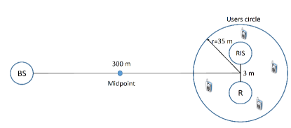
In the following simulations, we assume that the antennas at the BS and relay form a uniform linear array (ULA), while the reflecting elements at the RIS form a uniform planner array (UPA). The distances between the antennas and reflecting elements are calculated based on this deployment. As shown in Fig. 2, the users are randomly distributed inside a circle of radius m, whose center is m away from the BS. The relay and the RIS are assumed to be at the users’ circle center except in Fig. 5, where we assume the relay and the RIS are at the midpoint between the BS and the users circle center. In all simulations, unless otherwise noted, we assume that , , , and . The number of bits is assumed to be , so each reflecting element can have different phases, which are , where . Each point in the simulation figures is an average of 100 realization, where at each we distribute the users inside the circle randomly.
We evaluate the impact of changing the required rates at the users (), the number of users, and the number of reflecting elements on the required total power of the system. We assume that the channels between BS-relay, BS-RIS, and relay-RIS are all modelled as a Rician fading channels, where the LoS is available. We also assume that the channels of the three nodes (BS, relay, and RIS) and a user is a Rayleigh fading channel, where the LoS is not available. The channel attenuation coefficient between any two points is given by , where , if the LoS is available, and , if the LoS is not available, where dBi and dBi are the antenna gains in dBi at the transmitter and the receiver [28].
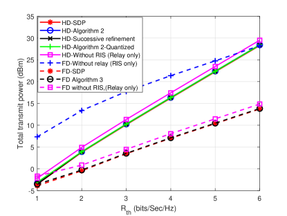
Fig. 3 shows how the total power behaves as a function of with the different approaches and different systems. It shows that the full-duplex proposed system (relay+RIS) performs better than all the other systems over all values of . In the full-duplex mode, the figure shows that the average contribution of power reduction over all values of is dBm, while the contribution of full-duplex relay is dBm. However, RIS performs better than the half-duplex mode when the value is greater than 6. The figure also shows that the full-duplex and half-duplex systems roughly provide the same performance when is small (e.g., ), while at the high values of , the system with an RIS and without a relay starts to perform better than the half-duplex system. From the algorithms’ perspective, although the figure shows the superiority of the SDP approach in both the full and half-duplex cases, the performance loss of Algorithm 2 or Algorithm 3 compared to the SDP approach is negligible.
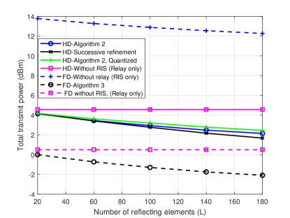
Fig. 4 shows the effect of increasing the number of reflecting elements at the RIS on the total required power. The figure shows that increasing the number of reflecting elements decreases the required power at BS and the relay. In the half-duplex mode, it can be seen that as the number of reflecting elements increases the successive refinement approach starts to perform better than Algorithm 2. However, since the number of required iterations in the successive refinement approach depends on the number of reflecting elements, its complexity becomes significantly higher compared to Algorithm 2. In particular, when , the successive refinement approach solves the problem of finding and times, which is much longer than what algorithm 2 needs to converge (cf. Fig. 7). The figure also shows that increasing the number of reflecting elements from 20 to 180 would reduce the required power by 1.5117 dBm if there is no relay (RIS-only) and 2.0882 dBm if there is a full-duplex relay with 5 antennas (the proposed model). This means that increasing the number of reflecting elements is more impactful in the presence of the relay than in its absence. To highlight this point further, we examine the effect of increasing when the channel of the second hop is weak in Fig. 5.
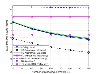
Fig. 5 shows the effect of increasing the number of reflecting elements at the RIS when both the relay and the RIS are located at the mid point between the BS and the users circle center, in which case the channel in the second hop is weak. In this figure, we can clearly see that increasing the number of reflecting elements, the amount of reduced power is high in the presence of relay and low in its absence. Specifically, it can be seen that increasing the number of reflecting elements from 20 to 180 reduces the required power by 0.28 dBm if there is no relay (RIS-only), 3.94 dBm if there is a full-duplex relay with 5 antennas (the proposed model), and 4.9176 if there is a half-duplex relay. The presence of relay makes the BS-RIS-relay and relay-RIS-user much stronger than the BS-RIS and RIS-user channels, which leads to increasing the effectiveness of each reflecting element. In addition, the figure shows that the contribution of reflecting elements in half-duplex mode is higher than that in the full-duplex mode. This holds since the degree of freedom in the half-duplex mode is twice in that in the full-duplex mode. In other words, in half-duplex mode, we optimize each phase-shift twice, one for the first phase and the other for the second phase (i.e., optimize and ), while in the full-duplex mode, we are allowed to optimize each phase shift once.
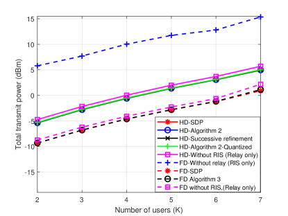
Fig. 6 shows that increasing the number of users in the system leads to increasing the required power to achieve an . The figure confirms that the presence of a relay whether a half or a full-duplex one improves the system energy efficiency significantly.
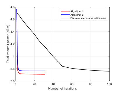
Fig. 7 plots the convergence of the proposed algorithms in the half-duplex case. The figure shows that Algorithms 1 and 2 converge at around the sixth iteration. However, the convergence of the successive refinement approach depends on the number of reflecting elements. Although the figure shows that the SDP approach achieves the best result, each iteration requires solving two SDP problems, which leads to a high computational complexity compared to the other approaches.
VII Conclusion
This paper proposes the coexistence of relay and RIS to improve the energy efficiency of multiuser systems. The paper studies and optimizes the system with different cases such as half-duplex mode, full-duplex modes, continuous and discrete phase shifts. It proposes solutions for joint beamforming at the BS, the relay, and the RIS to minimize the required total power (at the BS and the relay) under given QoS at the users. Since the formulated optimization problems are difficult, we propose suboptimal solutions that rely on the fact that the equivalent channel from the BS to the users is weak relative to the relay-user channel. For optimizing the phase shifts, we propose two solutions for the continuous phase shifts and two other solution for the discrete phases. Some of the solutions are proposed to seek the best performance and others to seek the low complexity with negligible performance loss. In the simulation results, we evaluate and compare the contribution of both the relay and the RIS under changing different system parameters. In general, the presence of both RIS and relay improves the energy efficiency significantly. The results reveal that the full-duplex system outperforms all the other systems. They also show that the presence of a relay strengthen the contribution of the reflecting elements especially if the channels to the users are weak on average.
References
- [1] M. Obeed and A. Chaaban, “Relay-reconfigurable intelligent surface cooperation for energy-efficient multiuser systems,” arXiv preprint arXiv:2104.02849, 2021.
- [2] E. Basar, M. Di Renzo, J. De Rosny, M. Debbah, M. Alouini, and R. Zhang, “Wireless communications through reconfigurable intelligent surfaces,” IEEE Access, vol. 7, pp. 116 753–116 773, 2019.
- [3] T. J. Cui, M. Q. Qi, X. Wan, J. Zhao, and Q. Cheng, “Coding metamaterials, digital metamaterials and programmable metamaterials,” Light: Science & Applications, vol. 3, no. 10, pp. e218–e218, 2014.
- [4] Q. Wu and R. Zhang, “Towards smart and reconfigurable environment: Intelligent reflecting surface aided wireless network,” IEEE Communications Magazine, vol. 58, no. 1, pp. 106–112, 2020.
- [5] B. Di, H. Zhang, L. Song, Y. Li, Z. Han, and H. V. Poor, “Hybrid beamforming for reconfigurable intelligent surface based multi-user communications: Achievable rates with limited discrete phase shifts,” IEEE Journal on Selected Areas in Communications, vol. 38, no. 8, pp. 1809–1822, 2020.
- [6] Q. Wu and R. Zhang, “Intelligent reflecting surface enhanced wireless network via joint active and passive beamforming,” IEEE Transactions on Wireless Communications, vol. 18, no. 11, pp. 5394–5409, 2019.
- [7] C. Huang, A. Zappone, G. C. Alexandropoulos, M. Debbah, and C. Yuen, “Reconfigurable intelligent surfaces for energy efficiency in wireless communication,” IEEE Transactions on Wireless Communications, vol. 18, no. 8, pp. 4157–4170, 2019.
- [8] C. Pan, H. Ren, K. Wang, W. Xu, M. Elkashlan, A. Nallanathan, and L. Hanzo, “Multicell mimo communications relying on intelligent reflecting surfaces,” IEEE Transactions on Wireless Communications, vol. 19, no. 8, pp. 5218–5233, 2020.
- [9] M. Cui, G. Zhang, and R. Zhang, “Secure wireless communication via intelligent reflecting surface,” IEEE Wireless Communications Letters, vol. 8, no. 5, pp. 1410–1414, 2019.
- [10] Q. U. A. Nadeem, H. Alwazani, A. Kammoun, A. Chaaban, M. Debbah, and M. S. Alouini, “Intelligent reflecting surface-assisted multi-user miso communication: Channel estimation and beamforming design,” IEEE Open Journal of the Communications Society, vol. 1, pp. 661–680, 2020.
- [11] P. Wang, J. Fang, X. Yuan, Z. Chen, and H. Li, “Intelligent reflecting surface-assisted millimeter wave communications: Joint active and passive precoding design,” IEEE Transactions on Vehicular Technology, pp. 1–1, 2020.
- [12] Q. Wu and R. Zhang, “Intelligent reflecting surface enhanced wireless network: Joint active and passive beamforming design,” in 2018 IEEE Global Communications Conference (GLOBECOM), 2018, pp. 1–6.
- [13] Q. U. A. Nadeem, A. Chaaban, and M. Debbah, “Opportunistic beamforming using an intelligent reflecting surface without instantaneous csi,” IEEE Wireless Communications Letters, vol. 10, no. 1, pp. 146–150, 2021.
- [14] Q. U. A. Nadeem, A. Zappone, and A. Chaaban, “Intelligent reflecting surface enabled random rotations scheme for the miso broadcast channel,” IEEE Transactions on Wireless Communications, pp. 1–1, 2021.
- [15] C. Huang, A. Zappone, G. C. Alexandropoulos, M. Debbah, and C. Yuen, “Reconfigurable intelligent surfaces for energy efficiency in wireless communication,” IEEE Transactions on Wireless Communications, vol. 18, no. 8, pp. 4157–4170, 2019.
- [16] E. Björnson and L. Sanguinetti, “Power scaling laws and near-field behaviors of massive mimo and intelligent reflecting surfaces,” arXiv preprint arXiv:2002.04960, 2020.
- [17] M. Di Renzo, K. Ntontin, J. Song, F. H. Danufane, X. Qian, F. Lazarakis, J. De Rosny, D. Phan-Huy, O. Simeone, R. Zhang, M. Debbah, G. Lerosey, M. Fink, S. Tretyakov, and S. Shamai, “Reconfigurable intelligent surfaces vs. relaying: Differences, similarities, and performance comparison,” IEEE Open Journal of the Communications Society, vol. 1, pp. 798–807, 2020.
- [18] X. Ying, U. Demirhan, and A. Alkhateeb, “Relay aided intelligent reconfigurable surfaces: Achieving the potential without so many antennas,” arXiv preprint arXiv:2006.06644, 2020.
- [19] Z. Abdullah, G. Chen, S. Lambotharan, and J. A. Chambers, “Optimization of intelligent reflecting surface assisted full-duplex relay networks,” IEEE Wireless Communications Letters, pp. 1–1, 2020.
- [20] Z. Zhang, X. Chai, K. Long, A. V. Vasilakos, and L. Hanzo, “Full duplex techniques for 5g networks: self-interference cancellation, protocol design, and relay selection,” IEEE Communications Magazine, vol. 53, no. 5, pp. 128–137, 2015.
- [21] S. Boyd, S. P. Boyd, and L. Vandenberghe, Convex optimization. Cambridge university press, 2004.
- [22] M. Grant and S. Boyd, “Cvx: Matlab software for disciplined convex programming, version 2.1,” 2014.
- [23] Q. Wu and R. Zhang, “Intelligent reflecting surface enhanced wireless network: Joint active and passive beamforming design,” in 2018 IEEE Global Communications Conference (GLOBECOM). IEEE, 2018, pp. 1–6.
- [24] Y. Sun, P. Babu, and D. P. Palomar, “Majorization-minimization algorithms in signal processing, communications, and machine learning,” IEEE Transactions on Signal Processing, vol. 65, no. 3, pp. 794–816, 2017.
- [25] X. Yu, D. Xu, and R. Schober, “Miso wireless communication systems via intelligent reflecting surfaces : (invited paper),” in 2019 IEEE/CIC International Conference on Communications in China (ICCC), 2019, pp. 735–740.
- [26] T. J. Cui, M. Q. Qi, X. Wan, J. Zhao, and Q. Cheng, “Coding metamaterials, digital metamaterials and programmable metamaterials,” Light: Science & Applications, vol. 3, no. 10, pp. e218–e218, 2014.
- [27] N. Kaina, M. Dupré, G. Lerosey, and M. Fink, “Shaping complex microwave fields in reverberating media with binary tunable metasurfaces,” Scientific reports, vol. 4, no. 1, pp. 1–8, 2014.
- [28] Q. Nadeem, A. Kammoun, A. Chaaban, M. Debbah, and M. Alouini, “Asymptotic max-min sinr analysis of reconfigurable intelligent surface assisted miso systems,” IEEE Transactions on Wireless Communications, pp. 1–1, 2020.