A discrete dislocation dynamics study of precipitate bypass mechanisms in nickel-based superalloys
Abstract
Order strengthening in nickel-based superalloys is associated with the extra stress required for dislocations to bypass the precipitates distributed in the matrix. Depending on the operating conditions and microstructure, a rich variety of bypass mechanism has been identified, with various shearing and Orowan looping processes gradually giving way to climb bypass as the operating conditions change from the low/intermediate temperatures and high stress regime, to the high temperature and low stress regime. When anti phase boundary (APB) shearing and Orowan looping mechanisms operate, the classical picture is that, at for a given volume fraction, the bypass mechanism changes from shearing to looping with increased particle size and within a broad coexistence size window. Another possibility, which is supported by indirect experimental evidence, is that a third “hybrid” transition mechanism may operate. In this paper we use discrete dislocation dynamics (DDD) simulations to study dislocation bypass mechanisms in Ni-based superalloys. We develop a new method to compute generalized stacking fault forces in DDD simulations, based on a concept borrowed from complex analysis and known as the winding number of a closed curve about a point. We use this method to study the mechanisms of bypass of a square lattice of spherical precipitates by edge dislocations, as a function of the precipitates volume fraction and size. We show that not only the hybrid mechanism is possible, but also that it is operates as a transition mechanism between the shearing and looping regimes over a wide range of precipitates volume fraction and radii. Based on our simulation results, we propose a simple model for the strength of this mechanism. We also consider the effects of a lattice misfit on the bypass mechanisms, which we approximate by an additional precipitate stress computed according to Eshelby’s inclusion theory. We show that in the shearing and hybrid looping-shearing regimes, a lattice misfit generally results in an increased bypass stress. For sufficiently high lattice misfit, the critical bypass configuration in attractive dislocation-precipitates interactions changes dramatically, and the bypass stress is controlled by the pinning of the trailing dislocation on the exit side of the precipitates, similar to what has been reported in the high-temperature creep literature.
keywords:
1 Introduction
Since their introduction in the 1950s, nickel (Ni)-based superalloys have emerged as the dominant class of structural materials in aerospace applications requiring mechanical and chemical resistance at high temperatures (Sims, 1984; Schafrik and Sprague, 2008; Pollock and Tin, 2006). Despite continuous progress in competing classes of materials (Zhao and Westbrook, 2003), Ni-based superalloys remain the reference class of materials for these applications. Although gas turbine engines have historically represented the archetypal target of Ni-based superalloys, other industries have benefited from their usage, including the automotive, the gas and oil exploration, the metal processing, and the nuclear industries (Matsuo et al., 1987; Sommitsch et al., 2012). Ni-based superalloys also find applications as materials for boilers, heat exchangers and tubomachinery in advanced ultra-supercritical (A-USC) fossil- and nuclear-based power generation (Rakowski et al., 2006; Stein-Brzozowska et al., 2013; Gandy and Shingledecker, 2014).
Ni-based superalloys owe their high-temperature mechanical properties to several factors (Reed, 2008). First, the face-centered cubic (fcc) structure of the Ni matrix guarantees that the alloys are both tough and ductile over the entire operative temperature window without suffering from a ductile to brittle transition. Second, among the fcc metals, Ni possesses relatively high activation energy of self-diffusion, thus endowing an intrinsic resistance to diffusional creep. Third, the presence of secondary phases, such as the coherent, ordered, intermetallic () precipitates, and carbides/borides typically residing on grain boundaries provide the high-temperature creep resistance by hindering dislocation motion and grain boundary sliding. Fourth, a rich composition of alloy elements is tailored to stabilize and enhance the various phases of the alloy and further improve the resistance to diffusional creep.
Order strengthening by precipitation is a consequence of the hindering effect that precipitates have on dislocation motion. The additional stress required for dislocations to bypass precipitates depends on the type of the underlying escape mechanism. Four types of mechanisms are possible. Two of them are essentially athermal, namely particle shearing and Orowan looping, while two mechanisms are mediated by mass diffusion, namely dislocation climb around particles, and to a lesser extent particle dragging (McLean, 1985). Which specific mechanism is dominant depends on both microstructural parameters (e.g. alloy composition, lattice misfit, precipitates size, morphology, and volume fraction) and external conditions (e.g. applied stress and operating temperature). At low and intermediate temperatures mass diffusion is slow, and therefore the athermal mechanisms of particle shearing and looping by dislocations are dominant. Together with the grain size, the precipitate size distribution and volume fraction are essential microstructural parameters influencing both monotonic and cyclic deformation of the superalloys (Ghonem et al., 1993; Alexandre et al., 2004; Pineau and Antolovich, 2009; Gv Boittin et al., 2012; Antolovich, 2015; le Graverend, 2019). Of particular importance is the role of the athermal mechanisms in controlling different regimes of creep deformation. For example, in the low temperature creep regime, approximately defined as (Pollock and Field, 2002), several single crystal superalloys with high precipitates volume fraction exhibit primary creep mediated by shearing of the precipitates by paired dislocations and dislocations ribbons (Kear and Oblak, 1974; Matan et al., 1999). A transition to secondary creep eventually takes place as dislocations percolate through the channels and form a geometrically-necessary and non statically-recoverable network that reduces the misfit energy and simultaneously inhibit further slip (Rae et al., 2000). At intermediate temperature, and correspondingly lower stresses, shearing becomes more difficult, and dislocations are typically confined to glide in the phase with local climb rearrangements, although precipitates shearing by paired dislocations is observed in the later stages of secondary creep (Pollock and Argon, 1992; Pollock and Field, 2002). In low volume fraction polycrystalline superalloys, proper looping around individual particles becomes possible, and the competition between shearing and looping is more evident (e.g. Reppich et al., 1982b; Lerch et al., 1984), especially when a bimodal size distribution of secondary and tertiary precipitates is present (Viswanathan et al., 2005). For these alloys, a rich map of deformation mechanism emerges, with various shearing processes gradually giving way to climb bypass as the operating conditions change from the low/intermediate temperatures and higher stress regime to the high temperature and low stress regime (Smith et al., 2016; Smith et al., 016b). The question of which is the dominant mechanism in a given creep regime emerged early in relation to an anomaly observed in the creep behavior of precipitation and dispersion hardened materials: standard power-law creep predicts abnormally high stress-dependence and activation energy of their secondary creep rate. This anomaly was eventually reconciled with theory by introducing the concept of a threshold stress in the power-law creep equation (Lund and Nix, 1976), although different explanations of the origin of such term have been proposed (McLean, 1985; Arzt and Wilkinson, 1986; Rösler and Arzt, 1990; Mishra et al., 1994; Arzt et al., 2001).
Order strengthening with precipitates bypassed by pairs of dislocations is particularly relevant for superalloys operating in the low/intermediate temperature regime. The classical picture that emerges from the vast literature dedicated to this subject (e.g. Reppich, 1982; Ardell, 1985; Martin, 1998) is that the mechanism of bypass depends on microstructural parameters such as precipitates volume fraction and average size. For fixed (and not too high) volume fraction and increasing particle size, it is well-established that the bypass mechanism transitions from from weakly-coupled sharing, through strongly-coupled shearing, to Orowan looping. Understanding how these mechanisms affect strength has been instrumental in the design of superalloys. For example, several commercial alloys have a microstructure corresponding to the transition between the weak and strong shearing mechanisms, which is the condition of “critical dispersion” yielding the maximum strength for a given volume fraction (Reppich, 1982). The shearing to looping transition is arguably less understood. Reppich et al. (1982b) point out that the transition takes place over a wide range of particle diameters, with both processes being distinct and observable side by side, probably due to the local variability of the precipitates microstructure. Nabarro and De Villiers (1995), however, suggest another possibility, where the transition may also take place by means of a hybrid looping-shearing process: under sufficiently high stress, the leading dislocation in the pair may form a loop which is stable around the precipitate until the approaching trailing dislocation drives the loop into the precipitate, forming APB, and then quickly shears it removing the APB. It should be noted that, this hybrid process is difficult to observe experimentally, because the shearing event is unstable. However, the hybrid process leaves a signature characterized by a planar slip deformation mode, and by the presence of single loops around precipitates and lack of hardening because the “latent” shearing events prevent accumulation of additional loops. Such signature was in fact recognized in secondary precipitates ( and nm) in superalloy René 88 DT under MPa stress at C by Viswanathan et al. (2005) and Unocic et al. (2008).
Several modeling techniques have been developed to predict the high-temperature strength and creep resistance of precipitation-hardened alloys (Kim et al. (2018, 2016); le Graverend et al. (2014); le Graverend and Harikrishnan (2021); Collins and Stone (2014)). Discrete Dislocation Dynamics (DDD) simulations have been employed extensively in the literature to shed light on the mechanisms of interaction between dislocations and precipitates (Mohles, 2004; Rao et al., 2004; Yashiro et al., 2006; Vattré et al., 2009; Queyreau et al., 2010; Huang et al., 2012; Hafez Haghighat et al., 2013; Li and Wang, 2014; Hussein et al., 2017; Lin et al., 2018; Ali et al., 2020; Fan et al., 2018). However, the hybrid mechanism described above was not reported in these studies, despite its strong, albeit indirect, experimental evidence. This fact may partially be attributed to the fact that APB forces on dislocations have so far been introduced ad-hoc in DDD simulations, possibly preventing the observation of this more complex hybrid bypass mode. The objective of this paper is to investigate the transition between the shearing and looping processes of precipitates by dislocation pairs, and understand if and under which conditions the hybrid looping-shearing mechanisms takes place. We begin by reviewing the classical theory of athermal precipitation strengthening in section 2. In section 3 we introduce a new method to compute generalized stacking fault forces in DDD simulations, based on a concept borrowed from complex analysis and known as the winding number of a closed curve about a point. We use this method to study the mechanisms of bypass of spherical precipitates arranged in a square lattice by edge dislocations, as a function of the precipitates volume fraction and average radius. We show that not only the hybrid looping-shearing mechanism is possible, but also that it operates as the transition mechanism between the shearing and looping regimes over a wide range of precipitates volume fraction and radii. Based on our simulation results, we propose a simple model for the strength of this mechanism. In the same section, we consider the effects of a lattice misfit on the bypass mechanisms. The lattice misfit is approximated by an additional precipitate stress computed according to Eshelby’s inclusion theory. We show that in the shearing and hybrid looping-shearing regimes, a lattice misfit generally results in an increased bypass stress. For sufficiently high lattice misfit, the critical bypass configuration in attractive dislocation-precipitates interactions changes dramatically, and the bypass stress is controlled by the pinning of the trailing dislocation on the exit side of the precipitates, similar to what has been reported in the high-temperature creep literature (see Arzt et al., 2001). The summary in section 5 concludes our work.
2 Theory of athermal precipitation strengthening
The theory of precipitation strengthening is vast, and detailed reviews can be found elsewhere (Kelly and Nicholson, 1963; Brown and Ham, 1971; Reppich, 1982; Ardell, 1985; Martin, 1998). The objective of this section is to briefly recall selected concepts that serve as the theoretical framework to interpret our simulation results.
2.1 Particle shearing
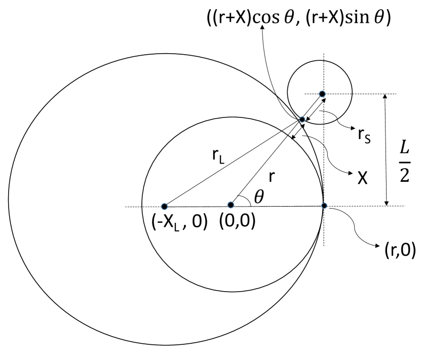
Consider a dislocation pinned by an array of point-particles with effective spacing , and subject to an applied shear stress . The breakaway condition is satisfied when the stress reaches a critical value corresponding the condition as , where is the particle strength. Note that the effective spacing , is not the average particle spacing on the glide plane. The effective particle spacing depends on stress, the argument being that an increasing stress causes a more bowed out dislocation between the pinning points, and consequently a larger number of particles that come into contact with it. This dependence is modeled by Friedel statistics (Friedel, 1964) (see also Fleischer, 1961), which assumes that the area swept by the dislocation due to an unpinning event contains only one new obstacle. For a square lattice of particles on the glide plane, this leads to the Friedel spacing , where is the dislocation line tension (typically approximated as ). In turn, the square lattice spacing is , where is the number of particles per unit area of the plane, which can be expressed in terms of the volume fraction and either the average particle radius , or the average radius at the intersection between the glide plane and the particles, as summarized in Fig. 1. This leads to the critical resolved shear stress
| (1) |
Several mechanisms may impart the particle strength , including chemical, stacking-fault, modulus, coherency, and order strengthening (Nembach and Neite, 1985; Ardell, 1985; Martin, 1998). Here we focus on order strengthening, which is the leading contribution to for dislocations interacting with precipitates in Ni-based superalloys. An antiphase boundary (APB) of surface energy density is left in the precipitate in the wake of the cutting dislocation, thus yielding a force , . Replacing this value in Eq. (2) yields the stress required for a single dislocation to shear the precipitate (Ham, 1968)
| (2) |
Because the shearing process is complete only when a second dislocation cuts the precipitate and restores the order, it is more significant to consider shearing by a pair of dislocations. Among other scenarios, Brown and Ham (1971) considered the case of weakly coupled dislocations, separated by a distance larger than the average particle diameter. The force equilibrium of the pair of leading and trailing dislocations, that is . This yields the estimate . If the trailing dislocation is almost straight then is the “mean free path” between two particles on a random straight line, hence . On the other hand is given by the Friedel spacing, thus leading to the weakly-coupled strengthening
| (3) |
Ardell (1985) has verified that for small , the scaling holds for several commercial alloys. For larger overaged particles, however, the precipitate diameter becomes comparable to the distance between the dislocation pair, and the assumptions of weak coupling does not apply. Instead the dislocation pair becomes strongly coupled while shearing the same precipitate. Hüther and Reppich (1978) considered this situation, and after equilibrium considerations obtained the following estimate for spherical particles
| (4) |
where is a fitting constant of order unity.
2.2 Orowan looping
When the conditions for shearing are not met, dislocations can bypass coherent particles by the process of Orowan looping, a concept that was initially developed to explain precipitation hardening by unshearable obstacles (Orowan, 1948). The idea is that a flexible dislocation with line tension can be bent by a critical stress satisfying , where is the radius of curvature between the obstacles. Although several estimates of the appropriate line tension have been proposed (see Kelly and Nicholson, 1963), a crude approximation using and , where is the inter-particle spacing, yields the celebrated result
| (5) |
where for a square lattice of particles .
Bacon, Kocks, and Scattergood (BKS) improved this estimate by considering the effect of the dislocation self-interaction on the Orowan stress (Bacon et al., 1973). The argument used to derive the critical bypass stress is that the applied force must be balanced by the self energy of the bowing line, that is , where is a conventional cut-off radius, is a fitting constant of the order unity, is an appropriate outer screening distance of the dislocation elastic fields, and for edge dislocations or for screw dislocations. Taking , and using the harmonic mean yields
| (6) |
Queyreau et al. (2010) considered the effect of subsequent loops piling-up around the precipitates. The loop pile-up is equivalent to an increased effective radius of the precipitate, hence a simple modification of Eq. (6) was proposed with replaced by an effective radius . Note that (6) applies only approximately to shearable particles because partial shearing may take place during the looping process, therefore altering the nominal parameters of the precipitates distribution.
Finally, note that deciding whether edge or screw dislocations control the bypass stress is not a trivial task. If we consider a standard dislocation line energy of the form , where is the angle from the perfect screw orientation, then we can compute the corresponding line tension as . The line tension of screw dislocations computed in this way is a factor higher than for edge dislocations, making screw dislocations about four times stiffer than edge dislocations. Then, the bypass stress should be controlled by edge dislocations in weakly-coupled shearing, and by screw dislocations in strongly-coupled shearing and looping. However, screw dislocations may also bypass precipitates by cross-slip. Since the main objective of the paper is to investigate the mechanisms of shearing to looping transition we will consider only the case of initially edge dislocations in our simulation results.
3 Computational Framework
The objective of this paper is to study the mechanisms of precipitates bypass by dislocations, with particular interest in the regime of transition between shearing and Orowan looping. In order to do so within the DDD framework, we need to develop a robust method to compute the forces exerted by generalized stacking faults on dislocations. Consider a slip plane in the material. Let be the generalized stacking fault energy density of that plane at point , and be the slip vector at that point. Then the misfit energy of the plane is
| (7) |
where is an elementary area element of the glide plane. Dislocations are lines of discontinuity for the function and consequently they are possible lines of discontinuity for the function . If is the dislocation velocity in the slip plane, then the transport theorem for discontinuous functions yields the rate
| (8) |
where . Here the upperscripts and simply indicate the two sides of glide plane separated by the dislocation, and and are the vectors orthogonal to the dislocation line in the glide plane pointing inside the corresponding region (). The configurational force per unit length on the dislocation due to generalized stacking fault is therefore
| (9) |
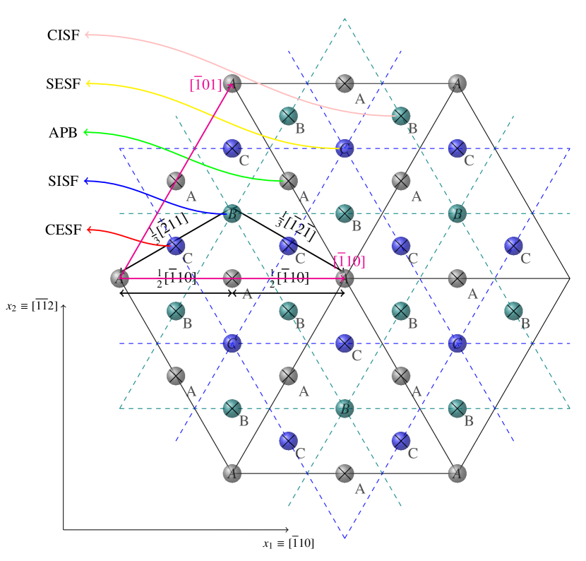
For a certain phase in the material (e.g. the fcc matrix -phase, or the precipitates -phase), the generalized stacking fault energy density function is typically constructed from ab-initio calculations by shifting the upper side of the crystal relative to the lower side by the slip vector . A discussion on the different types of stacking faults in the and phases has been provided in Vorontsov et al. (2012). In this work, the ab-initio data is fitted to the periodic function
| (10) |
where is a local (two-dimensional) slip vector on the glide plane, the ’s are wave vectors, the are matrices representing the symmetries of the lattice, and and are the corresponding fitting constants. The fitting procedure is detailed in A. After this one-time fitting procedure, the function is then fully available analytically.
Once the force (9) is obtained, it can be summed to the Peach-Koehler force routinely computed in DDD simulations. The total force is then used to obtained the dislocation velocity and evolve the dislocation configuration in time as already discussed elsewhere (e.g. Po and Ghoniem, 2014; Cui et al., 2017, 2018). However, it should be recognized that there is an intrinsic difficulty in the DDD framework, related to the computation of the force (9). In fact, while the Peach-Koehler force ultimately depends on the dislocation configuration, that is the collection of local Burgers vectors and tangent vector of each dislocation line element, the force (9) depends on the slip vectors on the two sides of any given dislocation during the simulation, that is the vectors and . The difficulty is then how to efficiently compute these vectors. To solve this problem Hussein et al. (2017) construct a mesh of each glide plane intersecting a precipitate, with cells storing the local accumulated slip vector . In this approach a planar mesh is created every time a new glide plane is needed, and great deal of precision must be used to update the slip vector once a dislocation sweeps its center. There is therefore a compromise between the accuracy of the force calculation, related to the planar mesh resolution, the corresponding memory requirement, and the computational cost associated with updating a large number of cell points. Here we pursue a different method, which does not require any meshing nor pointwise storage and update of the slip vectors . The tenet of the proposed method is that the identity of individual loops composing the dislocation network is maintained during the simulation. In our numerical implementation in the MoDELib (Mechanics Of Defect Evolution Library) code (Po and Ghoniem, 2015) this condition is satisfied, since MoDELib features a double topological representation of the dislocation network, where the identity of individual planar loops in the network is preserved even when segments undergo discrete reactions such as glissile junctions and cross-slip.
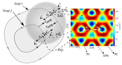
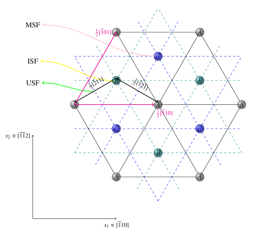
In order to describe the method, let us consider Fig. 2. The generalized stacking fault energy surface of the planes of the phase is shown in a local coordinate system with Cartesian axes and along and , respectively. The analytical expression of this function is given in eq. (10), and the fitting procedure is detailed in A. In this reference system, the vector points to the upper side of the crystal. Now consider a dislocation loop on this plane. The loop gives rise to a plastic distortion
| (11) |
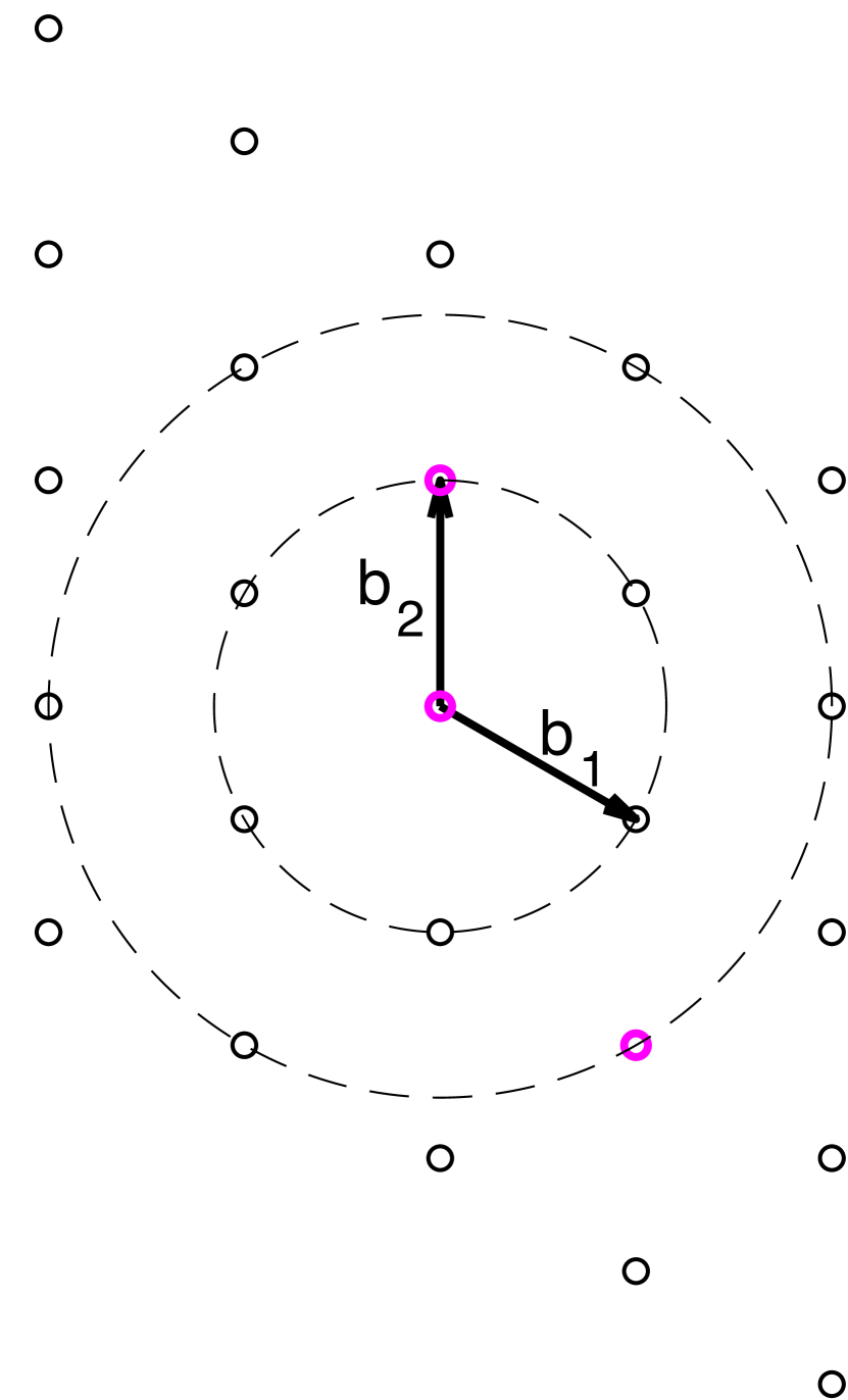
where is the slip surface of the loop, its Burgers vector, an elementary area element, and the normal to the loop plane which is right-handed to the loop tangent vector. It can be seen that the “inelastic part” of the displacement field caused by this distortion is associated with the solid angle subtended by the loop (Po et al., 2018). The slip vector is the jump in this inelastic displacement as the field point crosses the slip plane. If is oriented in the same sense as , points inside the loop and immediately above the plane slip by an amount relative to points below the plane, so that . If the orientation is opposite . If the point is outside the loop then . Since is uniquely determined by the orientation of the loop line tangent, the slip vector can efficiently be computed in a two-dimensional reference system on the slip plane as . Here is a quantity borrowed from complex analysis, and known as the the winding number of the loop about (Krantz, 1999). The winding number is an integer and it measures the number of times the loop wraps around . If and are in the same direction, then the loop is counterclockwise in the and plane of Fig. 2 and it yields when it contains , and zero otherwise. If and are in opposite directions, then loop is clockwise it yields if it contains , and zero for points outside. For more than one loop the total slip vector of any point in the plane can be obtained as
| (12) |
where the summation extends over all the dislocation loops in the plane.
The actual calculation of the generalized stacking fault force (9) along a certain dislocation segment proceeds as follows. Dislocation segments are populated with quadrature points. For each quadrature point with position we create two adjacent points, namely and , where is an infinitesimal positive scalar, as shown in Fig. 2. Eq. (12) is then applied to these two points, thus allowing the calculation of the generalized stacking fault (9). The lattice restoring force acting on dislocation segments are obtained by integrating this stacking fault force per unit length over all quadrature points.
As an example we can consider an explicit force calculation for the two points and in Fig. 2. Suppose that these points reside on loops which are shearing a precipitate. The point is on the outermost (leading) loop, while the point in on the innermost (trailing) loop. Then is outside both loops so that, according to (12), . On the other hand is inside the leading loop but outside the trailing loop, so that . Then the generalized stacking fault force at is , which is a force that tries to expel the leading dislocation from the precipitate. On the other hand, the point is inside the leading loop and outside the trailing loop, so that , while the point is inside both loops and . Then the generalized stacking fault force at is . This force attracts the trailing dislocation inside the precipitate.
It is worth noting that the method described above is completely general, and it does not require any ad-hoc “pairing” between dislocations. The method applies seamlessly to a variety of cases involving stacking fault forces acting on dislocations, like in the case of Shockley partials in the fcc phase, superpartials in the phase, and even to the more complex dislocation ribbons mentioned in the introduction. Moreover, the winding number is a lightweight and trivially parallelizable calculation which consumes negligible wall-clock time compared to dislocation-dislocation interactions in DDD simulations. It handles arbitrary-shaped loops, regardless of their convexity and self-intersection.
4 DDD simulation results
In this section we explore the mechanisms by which edge dislocations overcome a square lattice of precipitates. The radius of the precipitates intersected by the glide plane is , the square lattice spacing is , and the corresponding volume fraction is . The maximum value of occurs when and it is . As an initial validation phase, we first consider the interaction of a single dislocation with the square lattice of precipitates. The interaction of a pair of dislocations in considered next. The bypass mechanisms and their corresponding strength are reported as a function of and , and they are compared to analytical models. Note that, based on the method developed in section 3, no special rules are needed to compute the force exerted by generalized stacking faults on dislocations, even in the case of paired dislocations.
4.1 Single dislocation-precipitates interaction mechanisms
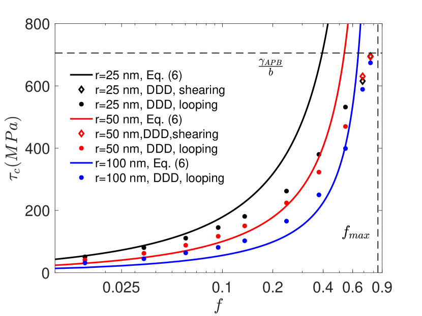
With reference to Fig. 3(a), a single dislocation is introduced within the phase of the Ni-based superalloy. The crystal is rotated such that the glide plane normal is along the global axis, while the slip direction is along the global axis. The glide plane is populated with a square lattice of spherical precipitate particles. Precipitates intersect the glide plane with a radius . The size of the box is varied from to , depending on the precipitate size and volume fraction. An external shear strain rate of is applied on the glide plane along the slip direction. The shear stress at which the dislocation is able to move through the precipitate square lattice is measured from the DDD simulations, and it is reported in Fig. 3(b) as a function of the volume fraction , and for three different precipitate radii . The strain rate was chosen to be sufficiently small that strain-rate effects on the bypass stress are negligible. The way the bypass stress is extracted from the simulations is described in D.
As expected, the observed bypass mechanism in these simulations is predominantly Orowan looping, apart from the case of high volume fraction, where shearing is observed. At low volume fraction (in particular ) and for smaller precipitate radii (e.g. ), the bypass stress measured in the DDD simulations is in good agreement with the BKS estimate for impenetrable particles given in Eq. (6). As the volume fraction increases, however, dislocations start to partially penetrate the precipitates, and the BKS model does not apply anymore. A deviation between the DDD results and the BKS model is observed for increasing . The discrepancy at intermediate is mainly due to the fact that partial shearing occurs before the looping process is complete. Hence, the effective radius and spacing of the precipitates deviate from their nominal values. The difference between penetrable precipitates and impenetrable precipitates assumed in the BKS model is more and more evident as the volume fraction approaches its maximum value . In this case dislocations encounter an almost continuum barrier which they are forced to shear when the applied stress reaches the critical value , which is independent of the particle radius. The DDD results indeed approach this value at large , independent of the value of .
4.2 Paired dislocations-precipitates interaction mechanisms
{forest}
for tree=
parent anchor=children,
child anchor=parent,
l sep’+=20mm,
where level=1l sep’=10mm,
where level=2l sep’=15mm,
where level¿=3l sep’=10mm,
s sep’+=10mm,
edge=arrow,line width=1.0pt,
,
[L interaction,rectangle,draw
[ ,edge label=node[midway,above,sloped] shear,label=above,left=1.5cm:(A)
[T interaction,rectangle,draw
[
,edge label=node[midway,above,sloped] shear,label=above,left=1.5cm:(A)
[T interaction,rectangle,draw
[ , edge label=node[midway,above,sloped] shear,label=above,left=1.5cm:(A1.1) [
 , no edge,label=above, left=1.5cm:(A1.2),label=below:weakly-coupled shearing]
]
[
, no edge,label=above, left=1.5cm:(A1.2),label=below:weakly-coupled shearing]
]
[ , edge label=node[midway,above,sloped] shear,label=above,left=1.5cm:(A2.1) [
 , no edge,label=above, left=1.5cm:(A2.2),label=below:strongly-coupled shearing]
]
]
]
[
, no edge,label=above, left=1.5cm:(A2.2),label=below:strongly-coupled shearing]
]
]
]
[ ,edge label=node[midway,above,sloped] loop,label=above,left=1.5cm:(B)
[T interaction,rectangle,draw [
,edge label=node[midway,above,sloped] loop,label=above,left=1.5cm:(B)
[T interaction,rectangle,draw [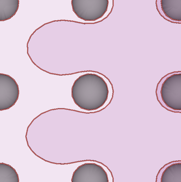 , edge label=node[midway,above,sloped] loop,label=above,left=1.5cm:(B1.1)
[
, edge label=node[midway,above,sloped] loop,label=above,left=1.5cm:(B1.1)
[ , no edge,label=above,left=1.5cm:(B1.2),label=below:looping]
]
[
, no edge,label=above,left=1.5cm:(B1.2),label=below:looping]
]
[ , edge label=node[midway,above,sloped] shear,label=above,left=1.5cm:(B2.1),
[
, edge label=node[midway,above,sloped] shear,label=above,left=1.5cm:(B2.1),
[ , no edge,label=above,left=1.5cm:(B2.2),label=below:hybrid looping-shearing]
]
]
]
]
, no edge,label=above,left=1.5cm:(B2.2),label=below:hybrid looping-shearing]
]
]
]
]
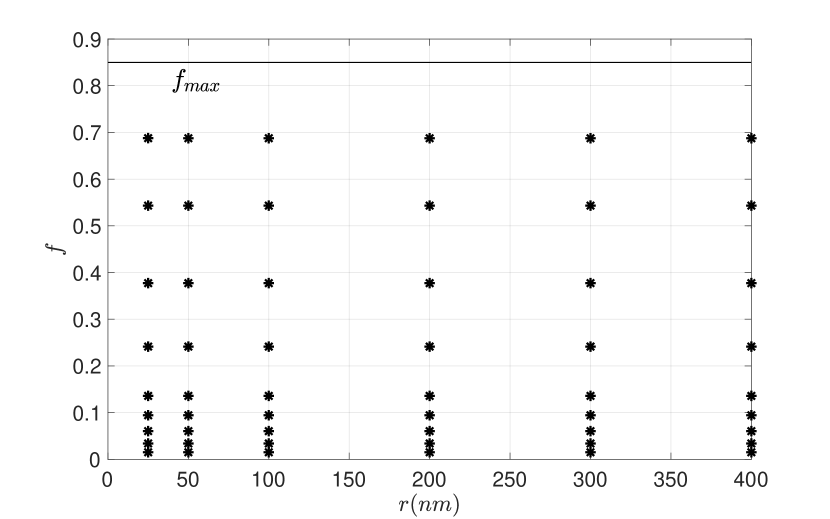
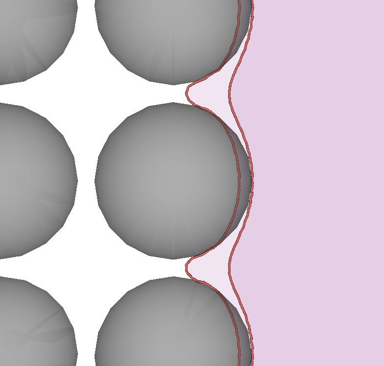
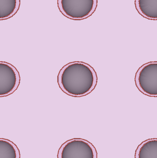
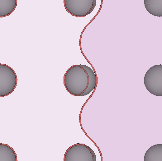
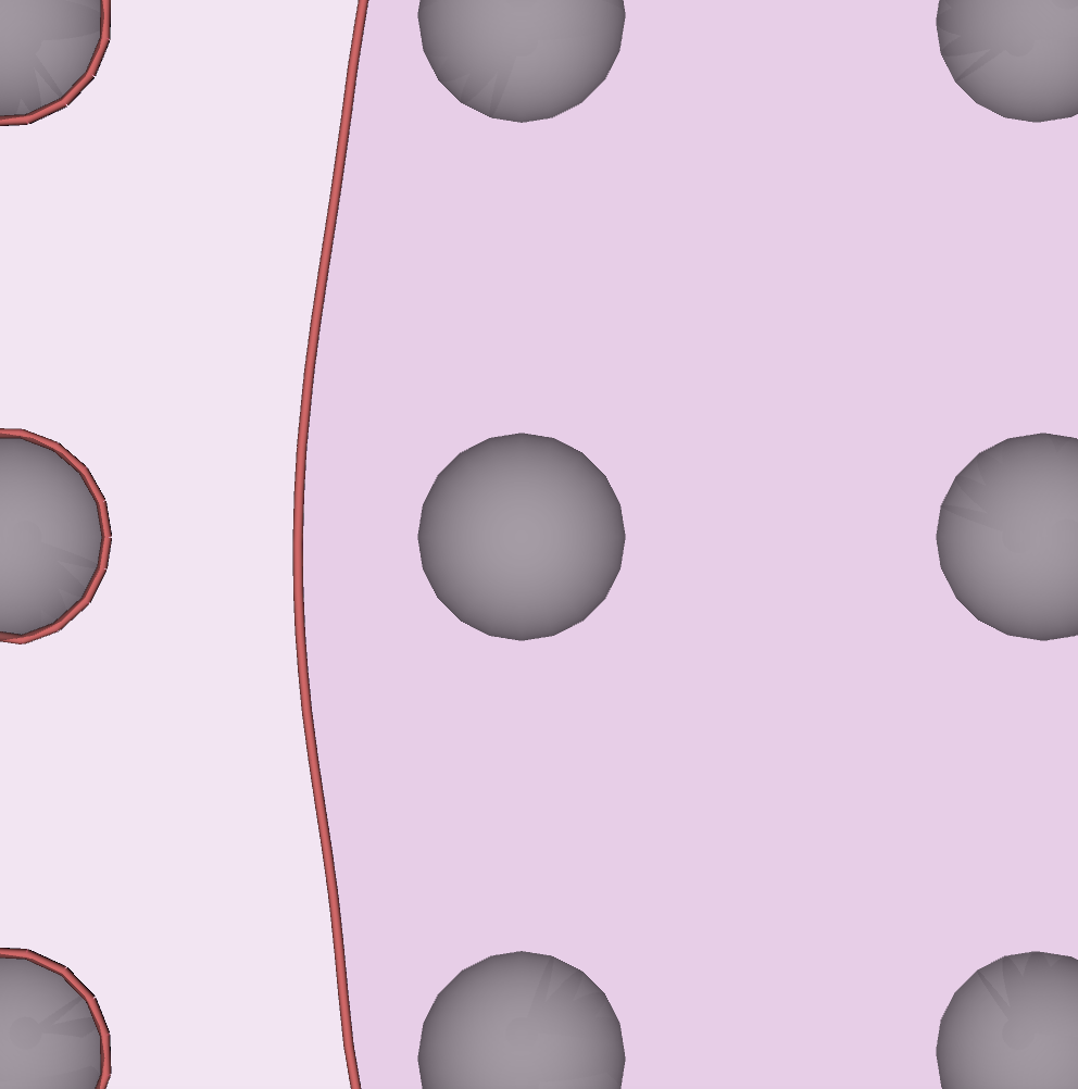
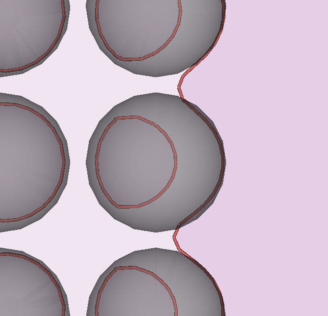
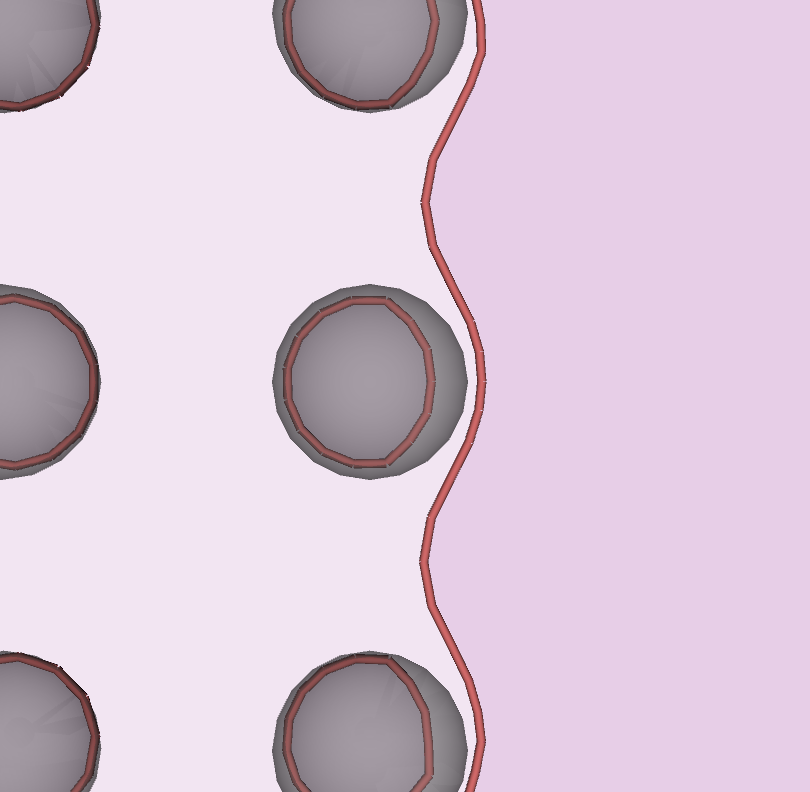
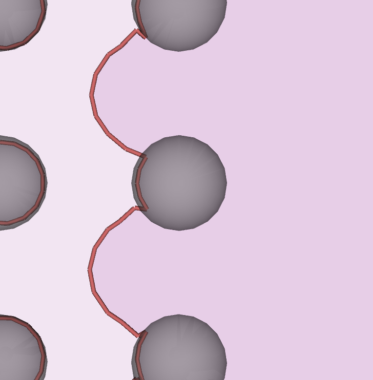
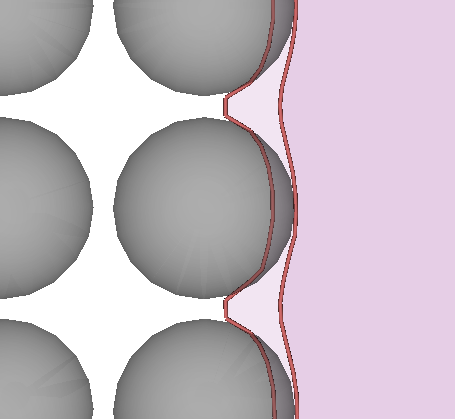
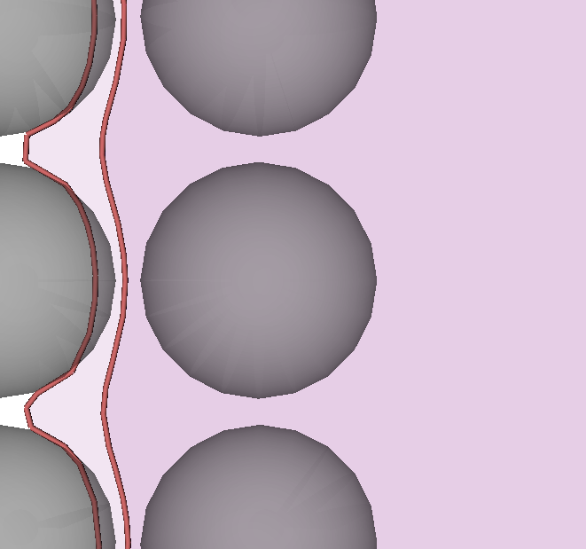
The same simulation setup described in section 4.1 is now used in the case of a pair of edge dislocations interacting with the square lattice of precipitate (Fig. 4(a)). The set of points explored in the DDD simulations is shown in Fig. 4(b). Depending on the precipitate radius and volume fraction , three distinct types of bypass mechanisms are observed, each with different scaling of the strength as a function of and . The possible outcomes of the interaction between the dislocation pair and the square lattice of precipitates is illustrated in the tree diagram of Fig. 5, which includes images extracted from the DDD simulations that are representative of the distinct bypass mechanisms. The white background in these images indicates the pristine area of the glide plane, while the lighter and darker magenta backgrounds indicate areas slipped by the leading dislocation only, and both leading and trailing dislocations, respectively.
The first discriminant between the bypass mechanisms is the type of interaction between the leading dislocation and the precipitates. Depending on the values of and , the leading dislocation can either shear the precipitates (image A), or loop around them (image B). In the case of shearing by the leading dislocation, the subsequent interaction of the trailing dislocation always results in shearing of the precipitate, so that the APB fault is removed. This mode of shearing can be either weakly-coupled (Eq. (3)) or strongly-coupled (Eq. (4)) depending on the values of and . For example, image A1.1 depicts the critical configuration of a weakly-coupled condition, with the leading dislocation inside an array of precipitates, and the trailing dislocation being almost straight outside the precipitates. Image A1.2 shows the corresponding configuration after the bypass. On the other hand, image A2.1 shows the critical configuration corresponding to the maximum shear stress, for the case of a high volume fraction. In this case the paired dislocations are strongly coupled and shear the precipitate cooperatively. Image A2.2 shows the paired dislocations after exiting the first array of precipitates, and ready to repeat the shearing process for the second array of precipitates.
The situation is more diverse in the case that the leading dislocation initially loops around the precipitates (image B in Fig. 5). In this case, the trailing dislocation encounters an array of precipitates surrounded by repulsive Orowan loops left in the wake of the leading dislocation. Our results indicate that two distinct bypass mechanisms may operate in this case. First, the trailing dislocation may also loop around the precipitates, creating secondary loops concentric to the existing ones (image B1.2). The bypass stress corresponding to the critical configuration (image B1.1) is then the stress necessary to create the secondary loops, which follows the BKS estimate (Eq. (6)). However, hardening is found in this process for two reasons: (a) because the effective radius of the precipitates is increased by the presence of the primary loops (Queyreau et al., 2010); (b) because the trailing loop embryo experiences a repulsion exerted by the primary loops surrounding the subsequent array of precipitates, especially in the case of intermediate and large .
The other possible pathway revealed by the DDD simulations seems to correspond to the hybrid shear-looping mechanism already mentioned in the introduction, which is discussed in Nabarro and De Villiers (1995) and was indirectly observed by Viswanathan et al. (2005) and Unocic et al. (2008). In this case, the approaching trailing dislocation drives the existing loop into the precipitate on the entry side. The bypass stress corresponds to the critical configuration in image B2.1, where the partially-collapsed primary loop reaches an unstable configuration. When this happens, the loop quickly collapses creating APB, and the trailing dislocation immediately sweeps the precipitate and removes the APB. Note that, in this process, the shearing event is difficult to observe because when the inner loop reaches the point of instability the cooperative shearing process happens almost instantaneously. This instability is associated with the difficulty to observe the process directly in experiments, which are more likely to capture either the state preceding the loop collapse (single “leading” loops around precipitates, without a stacking fault) or the state after the loop collapse (no loops and no stacking faults). However, indirect evidence of the process has been recognized. For example, in René 88 DT under high stress, Viswanathan et al. (2005) observed loops around precipitates, without obvious pairing of the dislocations, and with very few stacking faults. The authors explain this process as a secondary (trailing) dislocation pairing with a pre-existing (leading) loop so that the precipitate can be sheared by the pair of dislocations linked by a thin APB ribbon (see Fig. 15 in Viswanathan et al., 2005, for a sketch). The authors recognize that the annihilation of the pre-existing loop provides a strong driving force for this mechanism, and that ex-situ observations are unlikely to document it since dislocations and stacking faults are not observed inside the precipitates. Unocic et al. (2008) suggest the existence of a similar cooperative (hybrid) loop-shear mechanism in René 88DT by inferring it from two salient features of the structures. First, the very planar slip mode, which facilitates pairing of dislocations on the same glide plane. Second, the presence of only single loops around the precipitates. Unless this hybrid loop-shear mechanism were operative, intense strain hardening would be expected due to the accumulation of multiple loops around precipitates, which was not observed.
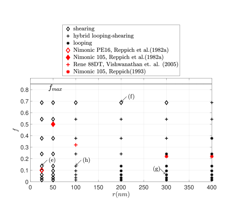
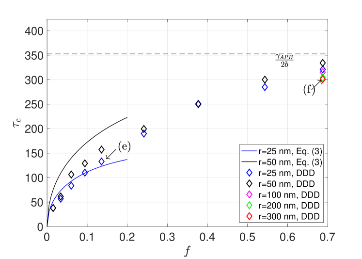
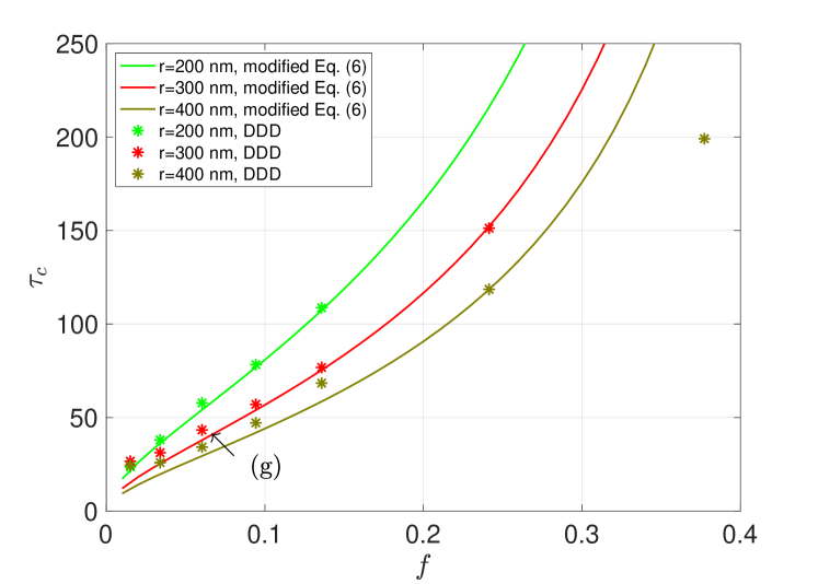
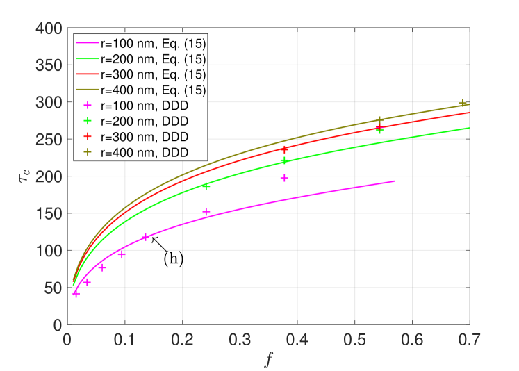
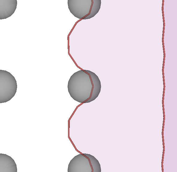
Fig. 6(a) presents a mechanism map for the three processes described above (shearing, looping, and hybrid mechanisms) as a function of volume fraction and average precipitate radius on the glide plane . The shearing regime occupies the low and the high portions of the map, while the looping regime occupies its high and low corner. Our results indicate that not only the hybrid mechanism is possible, but it is always found as the transition mechanism between the shearing and looping regimes over the explored range of precipitates volume fraction and radii. On the same map we also report the bypass mechanisms observed experimentally by Reppich et al. (1982a) in Nimonic PE16, Reppich (1993) in Nimonic 105 and Viswanathan et al. (2005) in René 88DT. The areas of the map occupied by the three mechanisms is in general consistent with the experimental observations. However, such comparison should be considered only qualitatively, since the bypass mechanism map depends on material properties and operating conditions that may very significantly when different experiments and simulations are considered.
In order to understand how hardening depends on the coordinates and , we compare the numerical simulations to appropriate analytical expressions in each regime. In the shearing regime, the DDD results are compared to the the weakly-coupled shearing model, Eq. (3), as shown in Fig. 6(b). Consideration of the weakly-coupled shearing mode is justified by the observation that, for small ( and ), the trailing dislocation is found mostly outside the precipitates at the critical configuration. A sample configuration, corresponding to the label (e) in Figs. 6(a) and 6(b), is illustrated in Fig. 6(e). The critical stress measured in the DDD simulations agrees with the weakly-coupled predictions for low and small (e.g. and ). Increasing and don’t satisfy the weakly-coupled shearing assumptions and deviations from the theoretical model emerge. Note that at the largest volume fraction explored in the simulations (), the strength measured in the simulations approaches the theoretical maximum value , with a weak dependence on . This value is half of the already discussed theoretical maximum for a single dislocation, and can be understood as the strength required for the dislocation pair to cut through a continuum barrier. An example of this situation, corresponding to the label (f) in Figs. 6(a) and 6(b), is illustrated in Fig. 6(f). Note that none of the shearing models presented in section 2 (Eq. (3) or Eq. (4)) predict this limit value since they were developed under the assumption of a low volume fraction.
In the Orowan looping regime, the bypass stresses are reported in Fig. 6(c). The bypass stress during the formation of an Orowan loop can be estimated by the BKS model given in Eq. (6) if we assume that precipitates are not partially penetrated by the looping dislocations. Note that the leading dislocation loops around the precipitates at a stress that is about half of the BKS estimate, since it is assisted by the repulsion from the trailing dislocation. The critical stress is then governed by the loop formed by the trailing dislocation. The trailing dislocation encounters precipitates surrounded by a repulsive loop, which effectively act as enlarged particles. Following Queyreau et al. (2010), an increased effective radius needs to be considered in the BKS model. However, our simulations also indicate that this correction is not sufficient in the range of radii and volume fraction considered in this regime. The difference between the effects of an augmented radius and the presence of the leading loop is that the loop exerts a repulsive stress field that further hinders the closure of the trailing loop. This difference can easily be observed in the shape of the corresponding critical configurations, as better described in B. This repulsion on the exit side leads to a further increase in the bypass stress, which here is simply accounted for by using a multiplicative factor in Eq. (6). The resulting modified BKS model, including both the effective radius and a multiplicative factor is found to be in good agreement with the our DDD simulations for , as shown in Fig. 6(c).
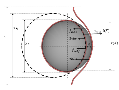
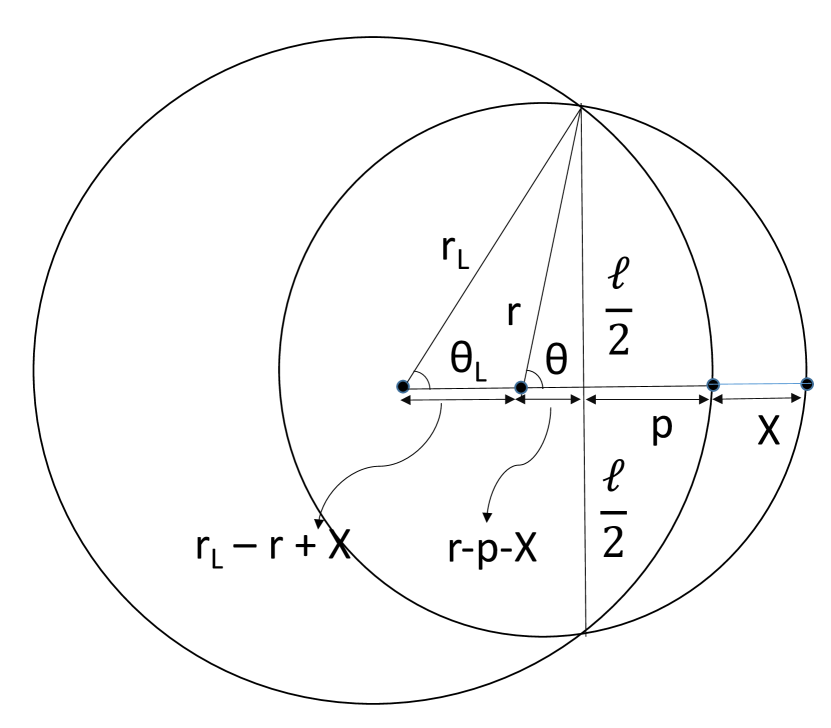
Finally, let us consider the hybrid looping and shearing regime. Also in this case the leading dislocation leaves Orowan loops around the precipitates. The approaching trailing dislocation however is able to drive the enter-side of these leading loops into the precipitates, thus creating APB. The critical configuration in this regime corresponds to the collapse of the leading loops. After the leading loops collapse, the trailing dislocation quickly shears the precipitates removing the APB. The critical stress for this process can be estimated with the help of the following model. Based on our results, we assume that the leading loop collapses when the trailing dislocation enters the precipitates. This condition is sketched in Fig. 7, which shows the periodic portion of length L between the bowed out parts of the trailing dislocation, and its interaction with a precipitate surrounded by the loop left behind by the leading dislocation. In the critical configuration, the enter side of the leading loop has partially been pushed into the precipitate creating APB. The enter-side of the leading loop remains approximately “parallel” to the approaching curved trailing dislocation, at a separation distance which can be estimated by the the same logic used in the case of strongly-coupled shearing. This yields (Reed, 2006). However, the chord subtended by loop inside the precipitate is different from the strongly-coupled shearing case, because the partially-collapsed loop cannot be approximated by a straight line. Instead, we assume that the shape of this partially-collapsed loop is approximately an arc of radius . Under this assumption, simple geometry allows to determine the expressions of and which are shown in C along with their derivation. With this geometry we can consider force equilibrium in the direction of motion of the trailing dislocation, for the system composed of the trailing dislocation and the right-half of the leading loop closer to the trailing dislocation, which is shown as partially collapsed in Fig. 7. The applied stress exerts a total force on this system. Given the self energy of the loop as (Hirth and Lothe, 1992), the right-half of the loop also experiences a force due to the loop self interaction that is
| (13) |
The trailing dislocation interacts with the left-half of the loop with a force similar to this contribution. Hence we will consider an effective self force , where is a fitting parameter. Moreover, the self-energy of the curved trailing dislocation, which we estimate using the BKS model, results in a force
| (14) |
Finally, these forces, which all act to collapse the loop, are balanced by the stacking fault force . Force equilibrium then yields the following critical stress for loop collapse
| (15) |
This equation models strengthening by the hybrid looping and shearing bypass mechanisms. It is plotted in Fig. 6(d) as a function of and for different values of chosen in the DDD simulation, and using . There is good agreement with the critical stress measured in our DDD simulations, and eq. (15).
4.3 Effects of a lattice misfit
The bypass mechanisms considered so far are valid when precipitates possess negligible lattice and elastic misfit. The lattice misfit
| (16) |
is an important property in alloy design, since it controls the interface energy and drives the precipitates coarsening kinetics (Reed, 2006). It also controls the precipitate morphology, with spherical precipitates typically observed for low misfit gradually giving way to cuboidal precipitates as approaches (Pollock and Tin, 2006). In this section we consider the effects of a lattice misfit on the three types of bypass mechanisms described in section 4.2. In our analysis we make the assumption that the elastic misfit is negligible, and that precipitates remain spherical. Under these assumptions, the presence of a lattice misfit results in an additional stress field that can can be calculated using the theory of Eshelby’s spherical inclusion (Mura, 1987), as detailed in E. Note that the resolved shear stress on any equatorial plane of the spherical precipitates vanishes identically. However, dislocations encounter precipitates at a average height from the equatorial plane, which corresponds to the average intersection radius . The resolved shear stress on this plane is shown in Fig. 8. The sign of the misfit stress depends on the sign of , and it flips both across the precipitate on the glide plane, and depending on whether the glide plane is above or below the equatorial plane. In any case, a given dislocation may experience either a repulsive or attractive interaction. In our analysis, we choose to vary in the range , and keep the height and side of the intersection, and the “sign” of the dislocation fixed. With this choice, in our analysis a positive misfit corresponds to a repulsive interaction, while a negative misfit corresponds to an attractive interaction. The misfit stress inside the precipitate is constant and equal to zero. Let us denote the bypass stress required for the dislocation pair to overcome the precipitate square lattice with zero misfit as . For each of the three types of bypass mechanisms described in section 4.2, we compute the additional stress necessary to bypass the same precipitate square lattice, and analyze the changes in the bypass mechanism as a function of the misfit .
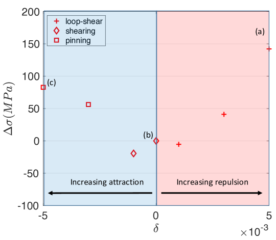
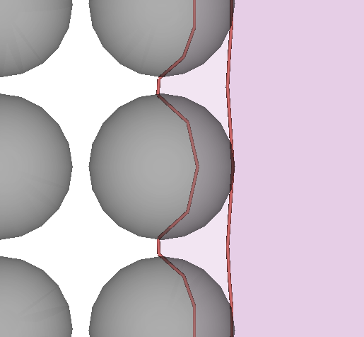
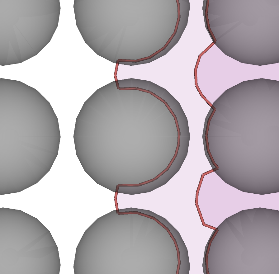
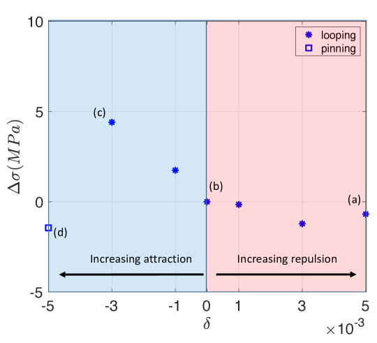
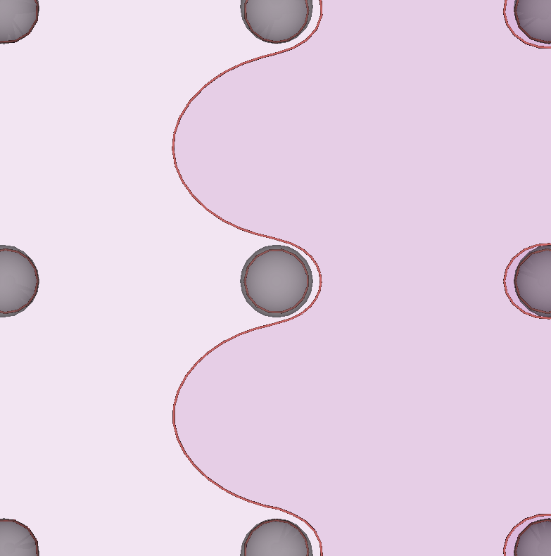
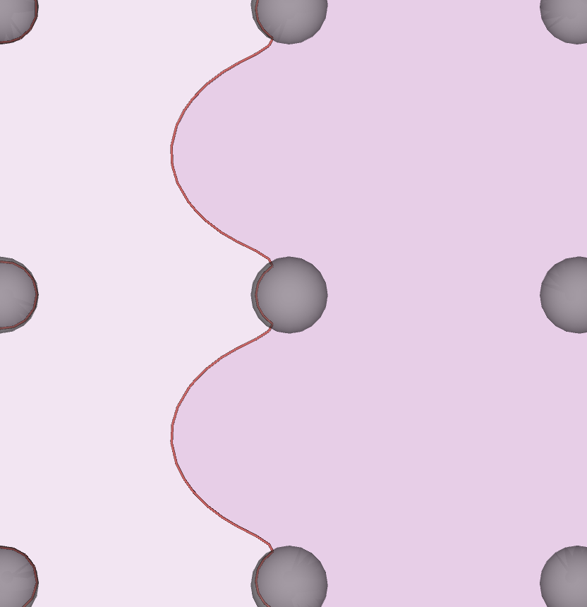
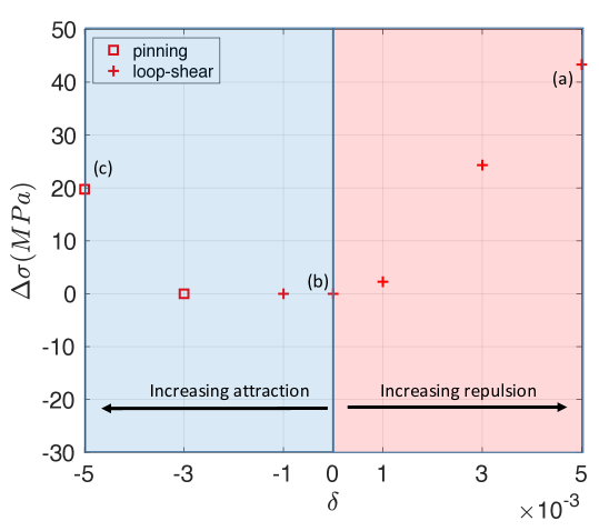
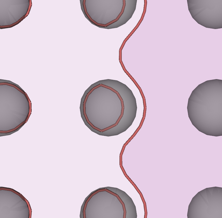
We first consider the shearing regime. We select a precipitates square lattice with parameters and which lies in this regime, and study the bypass mechanisms and strength as a function of . Our simulation results are reported in Fig. 9. For increasing repulsive interaction (increasing positive misfit), the bypass mechanism changes from shearing to the hybrid looping and shearing mechanisms discussed in the previous section. This is because the initial repulsive interaction between the leading dislocation on the enter-side of the precipitates prevents the leading from shearing the precipitates and facilitates the Orowan looping process. In addition, the opposite force on the exit side of the precipitate facilitates the closure of the leading loop (Fig. 9(a), ). The overall effect is a significant increase in the bypass stress. On the other hand, in the case of an attractive interaction, shearing is facilitated for both leading and trailing dislocations. However, the critical bypass configuration is controlled by the attractive interaction on the exit-side of the precipitates, which pins the trailing dislocation causing a significant increase in the bypass stress (Fig. 9(c), ). Hence a lattice misfit in general increases the bypass stress in the shearing regime.
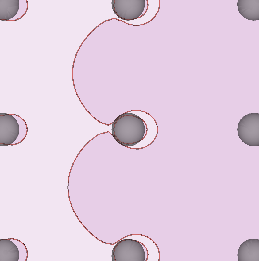

Next we consider the looping regime, with representative precipitate square lattice parameters and . Simulation results are summarized in Fig. 10. For a repulsive interaction (positive misfit here), the bypass mechanism is fundamentally unaltered, but the final state of the system may be significantly different. The critical stress still corresponds to the configuration where the trailing dislocation becomes unstable as it loops around the precipitates surrounded by the loops left behind by the leading dislocation. However, the positive misfit creates attractive forces on the back side of the precipitates (Fig. 10(a), ), which help in completing the looping process of the trailing dislocation. Compared to an absence of misfit (Fig. 10(b)), the shape of the bowed-out trailing dislocation reflects the attraction on the back side of the precipitates. Hence a positive misfit results in a decrease of the bypass stress, although this effect is very mild. The most striking difference, however, is that upon completion of the loop process, the attractive stress on the back side of the precipitate may be sufficient to cause the collapse of both loops. Note that there are no concentric loops in the rightmost column of precipitates in Fig. 10(a). For intermediate attractive interaction (Fig. 10(c), ), there is a repulsive stress on the back side of the precipitate, which opposes the advancement of the trailing dislocation and causes an increase of the stress necessary to close the trailing loop. Even in this case, once the trailing loop is able to close, the two concentric loops may collapse due to the attractive misfit stress on the entry side of the precipitate. Note the absence of concentric loops in the rightmost column of precipitates in Fig. 10(c). For even larger attractive interaction (Fig. 10(d), ), the attractive stress on the entry side of the precipitates is sufficient to collapse the leading loop before the trailing dislocation completes the looping process. As a consequence, the critical stress reduces and the bypass process becomes similar to the hybrid looping and shearing mechanism observed in the absence of a misfit. However, due to the high attractive stress the trailing dislocation remains pinned at the precipitate on the exit side, and this is the configuration corresponding to the critical bypass stress. Note that the effect of misfit stress is mild in this regime due to the presence of large channel width between the precipitates, which mitigates the effect of the attractive/repulsive interactions.
Finally, we consider the hybrid looping and shearing regime, with selected representative precipitate square lattice parameters and . For a repulsive interaction (positive misfit in Fig.11), the bypass stress increases with increasing misfit. This is because the trailing dislocation experience a repulsive force on the entry side, and because the loop left behind by the leading dislocation is also shifted towards the entry side causing an even greater repulsion (see Fig. 11(a), ). An attractive interaction, on the other hand, helps collapsing the leading loop. The effect on the bypass stress is mild until the attractive stress on the exist side pins the trailing dislocation and becomes the dominant factor in determining the critical configuration (see Fig. 11(c), ). Also in this regime, therefore, a lattice misfit increases the bypass stress.
In summary, for intermediate to high volume fraction, as is the case in the shearing and hybrid looping-shearing regimes, dislocation motion is hindered by a lattice misfit, independently of the type of interaction (attractive or repulsive). This phenomenon was also observed by Liu and Muraishi (2020) who reported hardening in the stress-strain response in the presence of precipitates with a lattice misfit. In a random distribution of precipitates, dislocations encounter an equal number of attractive and repulsive precipitate interactions. Hence, the presence of pinned dislocations at precipitates becomes a characteristic signature of strengthening by a lattice misfit. A similar strengthening by dislocation pinning was also proposed in the high-temperature creep literature (Arzt et al., 2001), when dislocation climb becomes the dominant bypass mechanisms around precipitates.
5 Summary and Conclusions
In this work we have developed a new method to compute the forces exerted by generalized stacking faults on dislocations within the DDD framework. The method is based on a concept borrowed from complex analysis, and known as the winding number of a closed curve about a point. Based on this quantity, the slip vector an any point on a slip plane can be computed if the loop topology of the dislocation network is preserved during the simulation. The method is general, and it applies seamlessly to Shockley partial dislocations in the fcc matrix, to superpartial dislocations in the phase, or to more complex situations such as dislocation ribbons observed in Ni-based superalloys.
We have applied this method to investigate the mechanisms of bypass of a square lattice of spherical precipitates by pairs of edge dislocations. The possible bypass mechanisms were explored as a function of two microstructural parameters, namely the average precipitate radius on the glide plane , and the precipitate volume fraction . DDD simulations were performed on a grid of points with and . A map of bypass mechanism was produced as a function of these two parameters. Consistently with the general theory of precipitation strengthening by athermal bypass mechanisms, the low and high regions on this map are controlled by APB shearing, while the high and low region is controlled by the Orowan looping process. However, our simulations indicate that the shearing and looping regime are separated by a regime where a different “hybrid” (looping-shearing) bypass mechanisms controls the bypass stress. This mechanism operates in the way described by Nabarro and De Villiers (1995), and it was indirectly observed by Viswanathan et al. (2005) and Unocic et al. (2008) in superalloy René 88 DT. In this hybrid mechanism the leading dislocation forms stable loops around precipitates while the approaching trailing dislocation drives these loops into the precipitates, forming APB, and then quickly shears them removing the APB. The analysis of the critical dislocation configuration during the bypass process also allowed us to derive an expression for the strength of this mechanism, which is in good agreement with the results of our DDD simulations.
We also studied the effect of a lattice misfit on the bypass mechanisms by introducing a precipitate stress according to Eshelby’s inclusion theory. Because dislocations statistically intercept precipitates on planes which are not equatorial planes, they experience either attractive or repulsive interactions with the spherical precipitates. We observed that both attractive and repulsive interactions lead to an increased bypass stress in the intermediate/high volume fraction regime, where some type of precipitates shearing is involved. In the low volume fraction regime, the large channel width mitigates the effects of misfit stresses. It was also found that a large lattice misfit may significantly alter the mechanisms of precipitates bypass, and hence the dependence of the bypass stress on the microstructural parameters and . In particular, for strongly-attractive interactions, the critical bypass configuration is often controlled by pinning of the trailing dislocation at the precipitates. In a random distribution of precipitates, dislocations encounter a statistically equal number of attractive and repulsive precipitate interactions. Hence, the presence of pinned dislocations at precipitates becomes a characteristic signature of strengthening by a lattice misfit. Interestingly, a similar strengthening mechanism by dislocation pinning is also reported in the high-temperature creep literature (Arzt et al., 2001), when dislocation climb becomes the dominant bypass mechanisms around precipitates. It is therefore possible that, for sufficiently large lattice misfit, pinning becomes the dominant strengthening mechanism independently of the bypass mechanism (shearing, looping or climb) operating in different regimes of creep deformation.
Acknowledgments
G. Po and S. Chatterjee acknowledge the U.S. Advanced Research Projects Agency–Energy (ARPA-E) under award number DE-SC0019157 with UCLA, and the U.S. Department of Energy, Office of Fusion Energy Sciences (FES), under award number DE-SC0019157 with UCLA, and related sub-awards with the University of Miami.
Appendix A Calculation of surfaces
In this work we use an analytical expression for the generalized stacking fault energy in the form
| (17) |
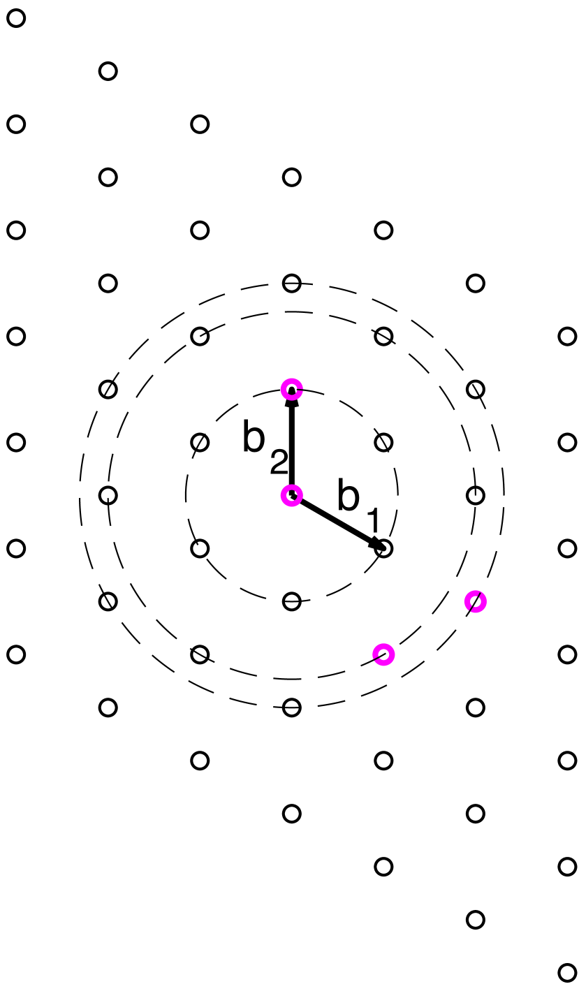
where is a local (two-dimensional) slip vector on the glide plane, the ’s are wave vectors, and the are matrices representing the symmetries of the lattice. Let be the matrix having in columns the basis vectors and of the glide plane lattice. Then the matrix is the matrix having as columns the basis vectors and of the corresponding reciprocal lattice. The Born-Von Karman periodicity condition implies that the wave vectors ’s have the form , where is a vector of integers.
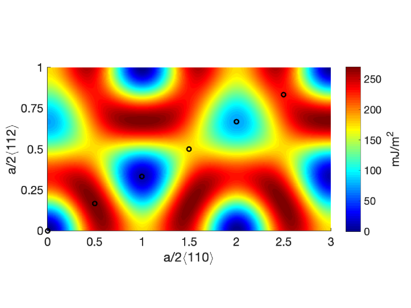
For the plane in the matrix fcc phase, we have
| and | (22) |
where is the magnitude of the Burgers vector in the phase. For the plane in the precipitate L phase we have
| and | (27) |
The three-fold rotation symmetry of the planes in both phases imply that the matrices ’s are
| and | (34) |
In each phase, the fitting constants and are found by imposing a set of conditions
| (35) |
where the pairs are obtained from ab-initio results from the literature. The specific conditions and choice of wave vectors for the and phases are detailed in Fig. 1(a) and Fig. 2(a), respectively.
| wave vector | [mJ m-2] | [mJ m-2] |
|---|---|---|
| 0 | 449.1 | |
| -511.5 | -326.1 | |
| 0 | -122.2 |
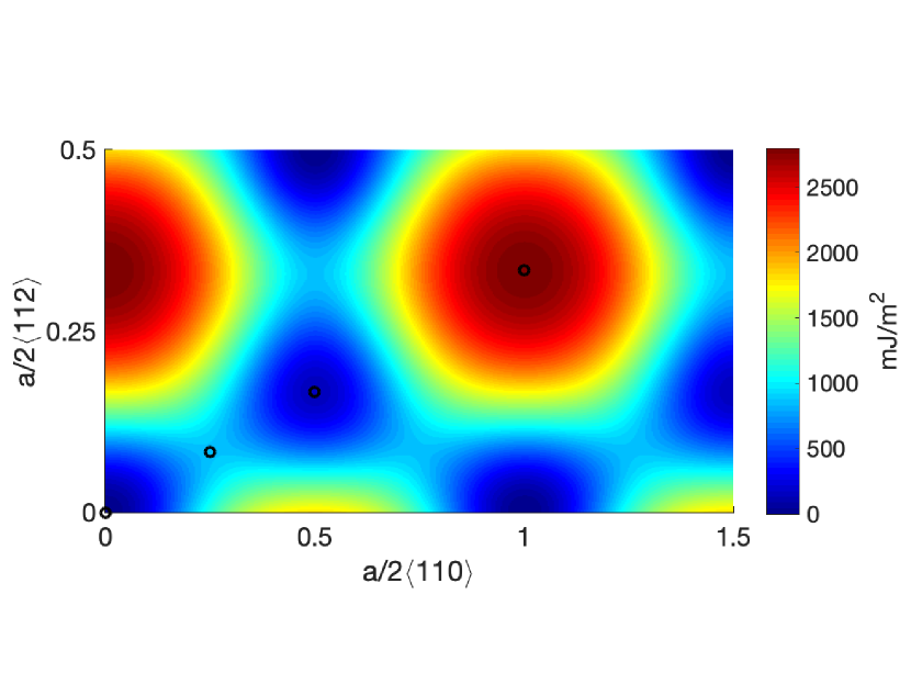
| wave vector | [mJ m-2] | [mJ m-2] |
|---|---|---|
| 0 | 58.61 | |
| -3.608 | 5.417 | |
| 0 | -49.17 | |
| 8.901 | -14.86 |
Appendix B Critical bypass configuration in the looping regime
We discussed dislocation pair bypass by the looping mechanism in Section 4.2. In Fig. 6(c), we observed that the bypass stress in the DDD simulation is larger than the BKS estimate (Eq. (6)) by a factor , even if a larger effective radius is considered Queyreau et al. (2010). Here, we provide a justification for this observation. In Fig. 3 we overlay two critical configurations extracted from the DDD simulations. In the foreground, the critical configuration showing the trailing dislocation bypassing a precipitate of radius and surrounded by a loop left behind by the leading dislocation. More faded in the background, the critical configuration of a single dislocation bypassing a larger precipitate of radius . It can be seen that these two critical configurations are not equivalent. In the case of the dislocation pair, the repulsive stress due to the leading loop on the back side of the precipitate hinders the closure of the trailing loop, and the trailing dislocation must protrude much deeper between the precipitates between closure can take place. This effect results in an increased bypass stress compered to the BKS model, even when an effective radius is considered.
Appendix C Calculation of
The critical configuration for the hybrid looping and shearing mechanism was shown in Fig. 7. The radius of curvature of the leading dislocation is such that . Let us assume that the center of the precipitate be the origin. The leading dislocation is inside the precipitate by a distance . Let us assume that the leading dislocation is shifted by to the right. Then it just touches the precipitate of radius as shown in Fig. 5. The circle, of which the leading dislocation is an arc, is assumed to be centered at and is of radius . Simple calculations lead to
| where | (36) |
Now we shift the leading dislocation by to the left, back to its original position ( Fig. 7) as shown in Fig. 5. Using simple geometric calculations, we obtain the length as
| where | (37) |
Appendix D Measurement of the bypass stress
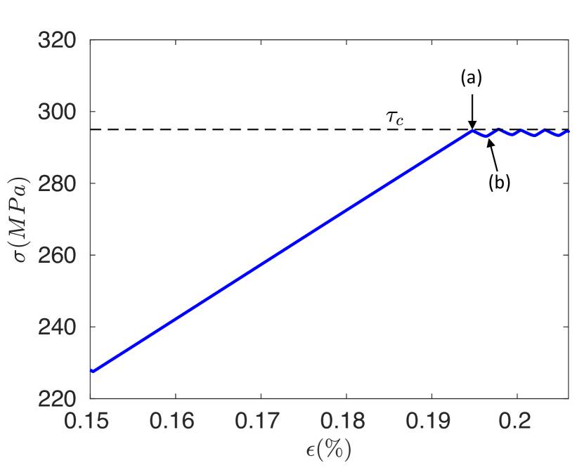
A typical stress-strain curve obtained from our simulations is shown in Fig. 6. A dislocation pair is pinned at a precipitate until the stress state is sufficiently high for the pair to bypass the precipitate (by shearing in this case). At constant applied strain rate, the bypass event corresponds to a drop in the stress (see point (a) in Fig. 6). The value of stress at which this occurs is the critical bypass stress which is recorded ().
Appendix E Stress field of an isotropic spherical inclusion
The lattice misfit can be understood as the linear strain induced by the precipitate in the “average” lattice. It corresponds to an eigenstrain or transformation-strain tensor
| (38) |
where is the identity tensor. In an isotropic material with shear modulus and Poisson’s ratio , the stress field induced by the inclusion can be written in terms of the auxiliary symmetric tensor
| (39) |
The stress field inside a spherical inclusion of radius is constant, and it reads (Mura, 1987)
| (40) |
where , and . On the other hand, the stress field of a point outside the inclusion is
| (41) |
where where is the center of the inclusion and .
References
- Alexandre et al. (2004) Alexandre, F., S. Deyber, and A. Pineau (2004). Modelling the optimum grain size on the low cycle fatigue life of a ni based superalloy in the presence of two possible crack initiation sites. Scripta Materialia 50(1), 25–30.
- Ali et al. (2020) Ali, M. A., I. López-Galilea, S. Gao, B. Ruttert, W. Amin, O. Shchyglo, A. Hartmaier, W. Theisen, and I. Steinbach (2020). Effect of precipitate size on hardness and creep properties of ni-base single crystal superalloys: Experiment and simulation. Materialia 12, 100692.
- Antolovich (2015) Antolovich, S. D. (2015). Microstructural aspects of fatigue in ni-base superalloys. Philosophical Transactions of the Royal Society A: Mathematical, Physical and Engineering Sciences 373(2038), 20140128.
- Ardell (1985) Ardell, A. J. (1985). Precipitation hardening. Metallurgical Transactions A 16(12), 2131–2165.
- Arzt et al. (2001) Arzt, E., G. Dehm, P. Gumbsch, O. Kraft, and D. Weiss (2001). Interface controlled plasticity in metals: dispersion hardening and thin film deformation. Progress in Materials science 46(3-4), 283–307.
- Arzt and Wilkinson (1986) Arzt, E. and D. Wilkinson (1986). Threshold stresses for dislocation climb over hard particles: The effect of an attractive interaction. Acta Metallurgica 34(10), 1893–1898.
- Bacon et al. (1973) Bacon, D. J., U. F. Kocks, and R. O. Scattergood (1973). The effect of dislocation self-interaction on the orowan stress. The Philosophical Magazine: A Journal of Theoretical Experimental and Applied Physics 28(6), 1241–1263.
- Brown and Ham (1971) Brown, L. and R. Ham (1971). Dislocation-particle interactions. In A. Kelly and R. Nicholson (Eds.), Strengthening Methods in Crystals, pp. 12. Elsevier.
- Collins and Stone (2014) Collins, D. and H. Stone (2014). A modelling approach to yield strength optimisation in a nickel-base superalloy. International Journal of Plasticity 54, 96–112.
- Cui et al. (2017) Cui, Y., G. Po, and N. Ghoniem (2017). Influence of loading control on strain bursts and dislocation avalanches at the nanometer and micrometer scale. Physical Review B 95(6), 064103.
- Cui et al. (2018) Cui, Y., G. Po, and N. Ghoniem (2018). Size-tuned plastic flow localization in irradiated materials at the submicron scale. Physical review letters 120(21), 215501.
- Fan et al. (2018) Fan, H., A. H. Ngan, K. Gan, and J. A. El-Awady (2018). Origin of double-peak precipitation hardening in metallic alloys. International Journal of Plasticity 111, 152–167.
- Fleischer (1961) Fleischer, R. L. (1961). Solution hardening. Acta metallurgica 9(11), 996–1000.
- Friedel (1964) Friedel, J. (1964). Dislocations: International Series of Monographs on Solid State Physics. Pergamon Press.
- Gandy and Shingledecker (2014) Gandy, D. and J. Shingledecker (2014). Advances in Materials Technology for Fossil Power Plants: Proceedings from the Seventh International Conference, October 22-25, 2013 Waikoloa, Hawaii, USA. ASM International.
- Ghonem et al. (1993) Ghonem, H., T. Nicholas, and A. Pineau (1993). Elevated temperature fatigue crack growth in alloy 718 - part ii: effects of environmental and material variables. Fatigue & Fracture of Engineering Materials & Structures 16(6), 577–590.
- Gv Boittin et al. (2012) Gv Boittin, D. L., A. Rafrayl, P. Caron, P. Kanoutél, F. Gallerneaul, and G. CailletaudZ (2012). Influence of’y’precipitate size and distribution on lcf behavior of a pm disk superalloy. Superalloys 2012, 167.
- Hafez Haghighat et al. (2013) Hafez Haghighat, S., G. Eggeler, and D. Raabe (2013). Effect of climb on dislocation mechanisms and creep rates in -strengthened ni base superalloy single crystals: A discrete dislocation dynamics study. Acta Materialia 61(10), 3709 – 3723.
- Ham (1968) Ham, R. (1968). Proceedings of conference on strength of metals and alloys. Trans. Japan Inst. Metals (Suppl.) 9, 52.
- Hirth and Lothe (1992) Hirth, J. and J. Lothe (1992). Theory of Dislocations. Krieger Publishing Company.
- Huang et al. (2012) Huang, M., L. Zhao, and J. Tong (2012). Discrete dislocation dynamics modelling of mechanical deformation of nickel-based single crystal superalloys. International Journal of Plasticity 28(1), 141 – 158.
- Hussein et al. (2017) Hussein, A. M., S. I. Rao, M. D. Uchic, T. A. Parthasarathy, and J. A. El-Awady (2017). The strength and dislocation microstructure evolution in superalloy microcrystals. Journal of the Mechanics and Physics of Solids 99, 146 – 162.
- Hüther and Reppich (1978) Hüther, W. and B. Reppich (1978). Interaction of dislocations with coherent, stress-free, ordered particles. Z. Metallk. 628, K71–K74.
- Kear and Oblak (1974) Kear, B. H. and J. Oblak (1974). Deformation modes ’precipitation hardened nickel-base alloys. Le Journal de Physique Colloques 35(C7), C7–35.
- Kelly and Nicholson (1963) Kelly, A. and R. Nicholson (1963). Precipitation hardening. Progress in Material Science 10, 151–391.
- Kim et al. (2016) Kim, Y.-K., D. Kim, H.-K. Kim, C.-S. Oh, and B.-J. Lee (2016). An intermediate temperature creep model for ni-based superalloys. International Journal of Plasticity 79, 153–175.
- Kim et al. (2018) Kim, Y.-K., D. Kim, H.-K. Kim, E.-Y. Yoon, Y. Lee, C.-S. Oh, and B.-J. Lee (2018). A numerical model to predict mechanical properties of ni-base disk superalloys. International Journal of Plasticity 110, 123–144.
- Krantz (1999) Krantz, S. G. (1999). Handbook of complex variables. Springer Science & Business Media.
- le Graverend (2019) le Graverend, J.-B. (2019). A hardening-based damage model for fast-evolving microstructures: Application to ni-based single crystal superalloys. International Journal of Plasticity 123, 1–21.
- le Graverend et al. (2014) le Graverend, J.-B., J. Cormier, F. Gallerneau, P. Villechaise, S. Kruch, and J. Mendez (2014). A microstructure-sensitive constitutive modeling of the inelastic behavior of single crystal nickel-based superalloys at very high temperature. International Journal of Plasticity 59, 55–83.
- le Graverend and Harikrishnan (2021) le Graverend, J.-B. and R. Harikrishnan (2021). A lattice-misfit-dependent micromechanical approach in ni-based single crystal superalloys. International Journal of Mechanical Sciences 195, 106229.
- Lerch et al. (1984) Lerch, B. A., N. Jayaraman, and S. D. Antolovich (1984). A study of fatigue damage mechanisms in waspaloy from 25 to 800 c. Materials Science and Engineering 66(2), 151–166.
- Li and Wang (2014) Li, R. and Z. Wang (2014). Parametric dislocation dynamics simulation of precipitation hardening in a ni-based superalloy. Materials Science and Engineering: A 616, 275 – 280.
- Lin et al. (2018) Lin, B., M. Huang, L. Zhao, A. Roy, V. Silberschmidt, N. Barnard, M. Whittaker, and G. McColvin (2018). 3d ddd modelling of dislocation–precipitate interaction in a nickel-based single crystal superalloy under cyclic deformation. Philosophical Magazine 98(17), 1550–1575.
- Liu and Muraishi (2020) Liu, J. and S. Muraishi (2020). Energy analysis of misfit hardening by parametric dislocation dynamics simulation. Computational Materials Science 178, 109630.
- Lund and Nix (1976) Lund, R. and W. Nix (1976). High temperature creep of ni-20cr-2tho2 single crystals. Acta Metallurgica 24(5), 469–481.
- Martin (1998) Martin, J. W. (1998). Precipitation hardening: theory and applications. Butterworth-Heinemann.
- Matan et al. (1999) Matan, N., D. Cox, P. Carter, M. Rist, C. Rae, and R. Reed (1999). Creep of cmsx-4 superalloy single crystals: effects of misorientation and temperature. Acta materialia 47(5), 1549–1563.
- Matsuo et al. (1987) Matsuo, T., M. Ueki, M. Takeyama, and R. Tanaka (1987). Strengthening of nickel-base superalloys for nuclear heat exchanger application. Journal of materials science 22(6), 1901–1907.
- McLean (1985) McLean, M. (1985). On the threshold stress for dislocation creep in particle strengthened alloys. Acta Metallurgica 33(4), 545–556.
- Mishra et al. (1994) Mishra, R., T. Nandy, and G. Greenwood (1994). The threshold stress for creep controlled by dislocation-particle interaction. Philosophical Magazine A 69(6), 1097–1109.
- Mohles (2004) Mohles, V. (2004). The critical resolved shear stress of single crystals with long-range ordered precipitates calculated by dislocation dynamics simulations. Materials Science and Engineering: A 365(1), 144 – 150. Multiscale Materials Modelling.
- Mura (1987) Mura, T. (1987). Micromechanics of defects in solids. Springer.
- Nabarro and De Villiers (1995) Nabarro, F. R. N. and F. De Villiers (1995). Physics of creep and creep-resistant alloys. CRC press.
- Nembach and Neite (1985) Nembach, E. and G. Neite (1985). Precipitation hardening of superalloys by ordered ?-particles. Progress in Materials Science 29(3), 177–319.
- Orowan (1948) Orowan, E. (1948). Symposium on internal stresses in metals and alloys. Institute of Metals, London 451.
- Pineau and Antolovich (2009) Pineau, A. and S. D. Antolovich (2009). High temperature fatigue of nickel-base superalloys–a review with special emphasis on deformation modes and oxidation. Engineering failure analysis 16(8), 2668–2697.
- Po and Ghoniem (2014) Po, G. and N. Ghoniem (2014). A variational formulation of constrained dislocation dynamics coupled with heat and vacancy diffusion. Journal of the Mechanics and Physics of Solids 66, 103–116.
- Po and Ghoniem (2015) Po, G. and N. Ghoniem (2015). Mechanics of defect evolution library (modelib). https://github.com/giacomo-po/MoDELib.
- Po et al. (2018) Po, G., M. Lazar, N. C. Admal, and N. Ghoniem (2018). A non-singular theory of dislocations in anisotropic crystals. International Journal of Plasticity 103, 1–22.
- Pollock and Argon (1992) Pollock, T. and A. Argon (1992). Creep resistance of cmsx-3 nickel base superalloy single crystals. Acta Metallurgica et Materialia 40(1), 1–30.
- Pollock and Field (2002) Pollock, T. and R. Field (2002). Dislocations and high-temperature plastic deformation of superalloy single crystals. In Dislocations in solids, Volume 11, pp. 547–618. Elsevier.
- Pollock and Tin (2006) Pollock, T. M. and S. Tin (2006). Nickel-based superalloys for advanced turbine engines: chemistry, microstructure and properties. Journal of propulsion and power 22(2), 361–374.
- Queyreau et al. (2010) Queyreau, S., G. Monnet, and B. Devincre (2010). Orowan strengthening and forest hardening superposition examined by dislocation dynamics simulations. Acta Materialia 58(17), 5586 – 5595.
- Rae et al. (2000) Rae, C., M. Rist, D. Cox, R. Reed, and N. Matan (2000). On the primary creep of cmsx-4 superalloy single crystals. Metallurgical and materials transactions A 31(9), 2219–2228.
- Rakowski et al. (2006) Rakowski, J., C. Stinner, et al. (2006). Nickel-base alloys for heat exchangers. In CORROSION 2006. NACE International.
- Rao et al. (2004) Rao, S. I., T. A. Parthasarathy, D. M. Dimiduk, and P. M. Hazzledine (2004). Discrete dislocation simulations of precipitation hardening in superalloys. Philosophical Magazine 84(30), 3195–3215.
- Reed (2006) Reed, R. C. (2006). The Superalloys: Fundamentals and Applications. Cambridge University Press.
- Reed (2008) Reed, R. C. (2008). The superalloys: fundamentals and applications. Cambridge university press.
- Reppich (1982) Reppich, B. (1982). Some new aspects concerning particle hardening mechanisms in ’precipitating ni-base alloys?i. theoretical concept. Acta Metallurgica 30(1), 87–94.
- Reppich (1993) Reppich, B. (1993). Particle strengthening. R. W. Cahn, P. Haasen and E. T. Kramer, eds, Materials Science and Technology 6: Plastic Deformation and Fracture, 311–357.
- Reppich et al. (1982a) Reppich, B., P. Schepp, and G. Wehner (1982a). Some new aspects concerning particle hardening mechanisms in precipitating nickel-base alloys-ii. experiments. Acta Metallurgica 30(1), 95–104.
- Reppich et al. (1982b) Reppich, B., P. Schepp, and G. Wehner (1982b). Some new aspects concerning particle hardening mechanisms in ’precipitating nickel-base alloys?ii. experiments. Acta Metallurgica 30(1), 95–104.
- Rösler and Arzt (1990) Rösler, J. and E. Arzt (1990). A new model-based creep equation for dispersion strengthened materials. Acta metallurgica et Materialia 38(4), 671–683.
- Schafrik and Sprague (2008) Schafrik, R. and R. Sprague (2008). Superalloy technology-a perspective on critical innovations for turbine engines. In Key Engineering Materials, Volume 380, pp. 113–134. Trans Tech Publ.
- Sims (1984) Sims, C. T. (1984). A history of superalloy metallurgy for superalloy metallurgists. Superalloys 1984, 399–419.
- Smith et al. (2016) Smith, T., T. Smith, L. Duchao, T. Hanlon, A. Wessman, Y. Wang, M. Mills, and M. Mills (2016, August). Determination of orientation and alloying effects on creep response and deformation mechanisms in single crystals of ni-base disk superalloys. In Superalloys 2016: Proceedings of the 13th Intenational Symposium of Superalloys, pp. 579–588. Wiley Online Library.
- Smith et al. (016b) Smith, T. M., R. R. Unocic, H. Deutchman, and M. J. Mills (2016b, June). Creep deformation mechanism mapping in nickel base disk superalloys. Materials at High Temperatures 33(4-5), 372–383.
- Sommitsch et al. (2012) Sommitsch, C., R. Radis, A. Krumphals, M. Stockinger, and D. Huber (2012). Microstructure control in processing nickel, titanium and other special alloys. In Microstructure evolution in metal forming processes, pp. 337–383. Elsevier.
- Stein-Brzozowska et al. (2013) Stein-Brzozowska, G., D. M. Flórez, J. Maier, and G. Scheffknecht (2013). Nickel-base superalloys for ultra-supercritical coal-fired power plants: Fireside corrosion. laboratory studies and power plant exposures. Fuel 108, 521–533.
- Unocic et al. (2008) Unocic, R., G. Viswanathan, P. Sarosi, S. Karthikeyan, J. Li, and M. Mills (2008). Mechanisms of creep deformation in polycrystalline ni-base disk superalloys. Materials Science and Engineering: A 483, 25–32.
- Vattré et al. (2009) Vattré, A., B. Devincre, and A. Roos (2009). Dislocation dynamics simulations of precipitation hardening in ni-based superalloys with high volume fraction. Intermetallics 17(12), 988 – 994.
- Viswanathan et al. (2005) Viswanathan, G., P. Sarosi, M. Henry, D. Whitis, W. Milligan, and M. Mills (2005). Investigation of creep deformation mechanisms at intermediate temperatures in rené 88 dt. Acta Materialia 53(10), 3041–3057.
- Vorontsov et al. (2012) Vorontsov, V., R. Voskoboinikov, and C. Rae (2012). Shearing of gamma’ precipitates in ni-base superalloys: a phase field study incorporating the effective gamma surface. Philosophical Magazine 92(5), 608–634.
- Wei et al. (2007) Wei, X.-M., J.-M. Zhang, and K.-W. Xu (2007). Generalized stacking fault energy in fcc metals with meam. Applied Surface Science 254(5), 1489 – 1492.
- Yashiro et al. (2006) Yashiro, K., F. Kurose, Y. Nakashima, K. Kubo, Y. Tomita, and H. Zbib (2006). Discrete dislocation dynamics simulation of cutting of precipitate and interfacial dislocation network in ni-based superalloys. International Journal of Plasticity 22(4), 713 – 723.
- Zhao and Westbrook (2003) Zhao, J.-C. and J. H. Westbrook (2003). Ultrahigh-temperature materials for jet engines. MRS bulletin 28(9), 622–630.