Energy-Efficient Coverage Enhancement of Indoor THz-MISO Systems: An FD-NOMA Approach
Abstract
Terahertz (THz) communication is gaining more interest as one of the envisioned enablers of high-data-rate short-distance indoor applications in beyond 5G networks. Moreover, non-orthogonal multiple-access (NOMA)-enabled schemes are promising schemes to realize the target spectral efficiency, low latency, and user fairness requirements in future networks. In this paper, an energy-efficient cooperative NOMA (CNOMA) scheme that guarantees the minimum required rate for the cell-edge users in an indoor THz-MISO communications network is proposed. The proposed cooperative scheme consists of three stages: (i) beamforming stage that allocates base-station (BS) beams to THz cooperating cell-center users using analog beamforming with the aid of the cosine similarity metric, (ii) user pairing stage that is tackled using the Hungarian algorithm, and (iii) power allocation stage for both the BS THz-NOMA transmit power and the cooperation power of the cooperating cell-center users, which are optimized sequentially. The obtained results quantify the energy efficiency (EE) of the proposed scheme and shed new light on the performance of multi-user THz-NOMA-enabled networks.
Index Terms:
Non-orthogonal multiple access (NOMA), user cooperation, full-duplex (FD), terahertz (THz) communication, energy efficiency (EE), beamforming, user pairing, power allocation.I Introduction
Emerging beyond-fifth generation (B5G) networks are witnessing revolutionary enhancement of data rate transmission for various innovative communication technologies and applications, including virtual reality (VR), augmented reality (XR), streaming K videos over wireless links, etc. In addition to that, the immersion of ultra-massive machine-type communication (umMTC) and internet-of-everything (IoE) in future wireless networks, that need ultra-reliable connectivity, are expected to become a reality in this decade [1]. Particularly, the vision of providing users with Tbps peak data rate, up to Gbps experience data rate, and almost perfect reliability is foreseen [2]. Nowadays, the trend of operating at high-frequency bands is apparent, for example, in fifth-generation (5G) new radio (NR) standard (i.e., 3rd Generation Partnership Project (3GPP) release ) some Millimeter-wave (mmWave) communications bands (i.e., between GHz to GHz) have been officially adopted. Nevertheless, for satisfying the aforementioned B5G networks demands, these mmWave communication bands might not be sufficient. Consequently, operating at higher frequency bands, sub-Terahertz (THz) (- THz) and THz (- THz) bands, where very large available contiguous bandwidth that spans from tens to even hundreds of GHz is one of the promising solutions for this problem [1, 3].
Traditionally, THz-band applications have been restricted to sensing, imaging, and localization. This was due to the lack of compact high-power signal transmitters and high-sensitivity detectors [4] at this band. Recent advancements in THz transceiver devices have paved the way for THz communications [1]. Those advancements can be grouped into four technology paths, namely, electronic, photonic, integrated hybrid electronic-photonic, and plasmonic transceiver designs [4, 1]. Operating at sub-THz and THz frequency bands comes at the cost of high propagation losses. In [3], Rappaport et al. highlight the additional challenges for wave propagation at frequencies beyond GHz, particularly that the free-space path loss and penetration loss increase significantly as we go to high frequencies, leading to shorter coverage areas. However, at these frequency bands, the wavelength and consequently the size of the antennas are very small, allowing for the use of highly directional antennas for ultra-precise beamforming [1].
Over the past few years, researchers have started investigating Non-orthogonal multiple access (NOMA) as a promising multiple access technique for accommodating more users in the same resource blocks [5, 6]. Most of the research has focused on power-domain NOMA (PD-NOMA) scheme which utilizes superposition coding (SC) at the transmitter and successive interference cancellation (SIC) decoding at the receiver. In the PD-NOMA scheme, multiple users share the same frequency and time resources and the channel gain differences are exploited at the receiver to separate the multiplexed user’s signals using the SIC decoding [5], which offers significant improvements in connectivity and spectral efficiency. Also, the in-band user-assisted cooperative side links are proposed in the literature to enhance the spectral efficiency for the cell-edge users as well as the network energy efficiency [7].
In this paper, by utilizing the NOMA principle along with full-duplex (FD) cooperative side links, we propose an energy-efficient user cooperative scheme that will guarantee the minimum required rate for cell-edge users in an indoor THz-multiple-input-single-output (MISO) communications network. Particularly, due to the high propagation losses in THz networks, cell-edge users might receive very weak THz beams from the base station (BS) and eventually suffer from a low data rate experience that is below their expected minimum required rate. Hence, with the aid of user-assisted cooperative side links and FD-NOMA scheme, this minimum required rate for cell-edge users can be guaranteed. The proposed cooperative scheme consists of three stages: (i) a beamforming stage that allocates beams to THz cooperating cell-center users using analog beamforming with the aid of the cosine similarity metric, (ii) a user pairing stage of THz cell-center users and user-assisted cell-edge users where a common matching algorithm, the Hungarian algorithm, that pairs users based on the Euclidean distance, is utilized and (iii) a power allocation stage where both the THz-BS NOMA transmit power and the cooperation power of the cooperating cell-center users are optimized sequentially. Each of the aforementioned stages is designed to contribute to decreasing the consumed power in the network to make our proposed scheme energy-efficient.
The amount of work in the THz-NOMA-enabled networks is still limited [8, 9, 10]. In [8], in order to maximize the network throughput, the authors solved an optimization problem that involves beamforming, power allocation, and sub-band assignment. Through numerical simulations, the authors demonstrated the superiority of the proposed scheme compared to the THz-OMA counterpart. In [9], a downlink heterogeneous THz-NOMA cache-enabled system with imperfect SIC is proposed. An energy efficiency (EE) maximization problem that includes user clustering, beamforming, and power allocation is formulated and then solved by dividing the original problem into three sub-problems. Through simulations, the authors show that the proposed enhanced K-means algorithm for user clustering and the proposed alternating direction method of multipliers for power allocation can achieve higher EE performance for the proposed network. In [10], a machine-type communication downlink sub-THz-NOMA enabled system to enable massive connectivity of devices has been analyzed. An EE maximization problem has been solved via unconstrained then constrained optimization. Through simulations, the authors show that the proposed system attains better performance compared to its counterpart in the mmWave band. There is no existing work that combines multi-user indoor MISO-NOMA in THz band with user-assisted cooperative side links for coverage enhancement of cell-edge users.
The main contributions can thus be summarized as follows;
-
•
Proposing an energy-efficient user-assisted full-duplex cooperative NOMA scheme that guarantees the minimum required rate for cell-edge users in multi-user indoor THz-MISO systems.
-
•
Developing the proposed scheme in three stages: (i) analog beamforming stage with the aid of the cosine similarity metric, (ii) user pairing stage for THz cooperating cell-center users and cell-edge users, and (iii) a power allocation stage for both the BS transmit power and the cooperation power of the cooperating cell-center users.
-
•
Investigating the effect of changing different network parameters through simulations, such as, the BS transmit power levels and cell-edge users’ minimum required rate on the EE of the network. The obtained results are bench-marked with the mmWave-NOMA counterpart scheme.
The remainder of this paper is organized as follows. In Section II, we provide the channel model and the system model of the proposed THz-MISO NOMA-enabled scheme. The details of the proposed scheme are presented in Section III. Simulation results are provided in Section IV. Finally, paper conclusions and future research directions are given in Section V.
II Channel Model and System Model
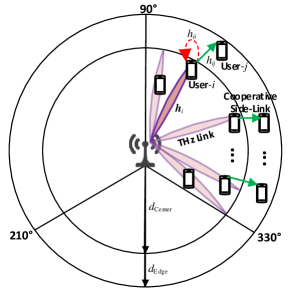
The system model of the proposed multi-user indoor THz-MISO cooperative NOMA (CNOMA) scheme is depicted in Fig. 1. Consider a downlink system with a single BS equipped with one radio frequency (RF) chain and -antenna phased arrays serving (i) cell-center users through analog beamforming (ABF) and (ii) cell-edge users through user-assisted full-duplex decode-and-forward (DF) cooperative side links by a subset of cooperating users. All the users are equipped with a single antenna element. To facilitate the investigation of the proposed CNOMA scheme, this paper assumes that equals . In this work, due to the requirement of low power consumption and hardware cost, we consider the ABF structure in the BS, which utilizes the single-phase shifter (SPS) implementation [11]. Also, for decreasing the computational complexity, it is assumed that the BS has full channel state information (CSI) and distance information for all users in the network, this assumption is also adopted by [8, 9]. In the BS, each antenna is driven by a phase shifter (PS) and a power amplifier (PA). The elements of the precoding vectors are complex numbers, its phase is controlled by the phase shifters and its modulus is controlled by the power amplifiers [11].
II-A Indoor THz Channel Model
In this subsection, we discussed the indoor THz channel model. In the THz band, the high path loss resulting from spreading loss and molecular absorption loss limits the scattering phenomenon. This makes THz communication links sensitive to obstacles blockage such as walls, and leads to large path loss difference between the direct paths and blocked paths. For example, in an indoor THz system, Priebe and Kurner [12] reported that when the line-of-sight (LoS) exists, the first-order reflections are attenuated on average more than dB, and the second-order reflections are attenuated on average more than dB. From this, one can conclude that the non-line-of-sight (NLoS) paths of THz channels are very limited. Therefore, in this work similar to [9], we consider the LoS paths only. Hence, the channel gain vector of the -th user on the -th user pair can be expressed as
| (1) |
| (2) |
where denotes the path loss incurred by the THz signal that is transmitted from the BS on frequency to the -th user that is meters apart from the BS. and denote the antenna gains of the BS and the array steering vector toward user- of the -th user pair, respectively. Equation (2) shows the two multiplicative factors that contribute to the path loss of THz signals, namely, the spreading loss and the molecular absorption loss . The term denotes the frequency-dependent absorption coefficient for different isotopologues of water vapor molecules. It is worthy to note that, in a regular medium, the main contributor of the total absorption loss comes from water vapor molecules and its loss far exceeds the contribution of other air molecules [9]. The speed of light is denoted by . The term represents the array steering vector for uniform linear array (ULA) and can be represented as [9]
| (3) |
where denotes the physical angle-of-departure of the THz beam. The cooperative side-link channel model also follows the one in (1); since in-band user-assisted cooperative communications paradigm is adopted [7, 13].
II-B System Model and Formulation
In this subsection, we present the details of the proposed multi-user indoor THz-MISO NOMA-enabled system and its energy-efficiency formulation. For mathematical convenience, we focus the analysis on the signaling within one NOMA user pair (i.e, the cooperating cell-center user- and cell-edge user-), the remaining user pairs can be analyzed similarly, since in this work, each THz cooperating cell-center user is served by one precoding vector on an orthogonal channel which can be a time slice or a sub-carrier frequency channel. With the adoption of the PD-NOMA scheme, the BS transmits superimposed signal towards the -th user pair is
| (4) |
where represents the precoding vector formed toward -th user pair, represents the SC signal for the -th user pair, and denote the power fractions assigned by the BS for cooperating cell-center user- and cell-edge user-, respectively. and denote the transmit messages of cooperating cell-center user- and cell-edge user-. denotes the BS transmit power for the -th user pair (i.e., per-channel use).
As depicted in Fig. 1, the received signal at the -th cooperating cell-center user on the -th user pair while considering FD relaying mode for the cooperative side link is
| (5) |
where represents the self-interference (SI) channel gain for the -th user of the -th user pair. represents the SI signal of the full-duplex link that arrives at the -th user. represents the cooperative transmit power of the -th user of the -th user pair. denotes the noise seen at user- of the -th user pair. The second term in (5), represents the intended signal for the -th user of the -th user pair that will be extracted by performing the SIC decoding procedures. On the other hand, the received signal at the -th cell-edge user on the -th user pair can be expressed as
| (6) |
where denotes the cooperative side-link channel gain between user- and user- of the -th user pair. represents the transmit signal from user- to user- of the -th user pair. denotes the noise seen at user- of the -th user pair. Now, we can express the signal-to-noise-interference ratio (SINR) when decoding the -th user signal at the -th user of the -th user pair as
| (7) |
where denotes the SI parameter, and its value ranges between . When , this refers to the perfect SI cancellation scheme. On the other hand, when , this refers to the scheme where there is no SI cancellation at the -th cooperating cell-center user. denotes the noise power. After performing the SIC decoding procedures, the SINR when user- decodes its own signal can be expressed as
| (8) |
The signal-to-noise ratio (SNR) seen at the cell-edge user- on the -th user pair can be represented as
| (9) |
At this point, we can represent the achievable rate of decoding user- signal at user- and the achievable rate when user- decodes its own signal as
| (10) |
| (11) |
where is the available contiguous bandwidth of the THz channel window. According to [14], the achievable rate when user- decodes its own signal can be expressed as
| (12) |
In the following, we express the energy efficiency of the system that can be defined as \saythe ratio between the achievable sum rate and the total power required to achieve this rate (Bits/Joule) [15] for the orthogonal channels
| (13) |
where is the power amplifiers’ inefficiency at the THz BS as well as at the cooperating cell-center users. is the circuit power consumption and can be expressed as [9]
| (14) |
where is the base-band power consumption, is the number of RF chains at the BS, is the RF chain power consumption, is the number of power amplifier/phase shifters at the BS, is the power consumption of each power amplifier, and is the power consumption of each phase shifter.
III The Proposed Energy-Efficient CNOMA Scheme
In this section, we discuss in detail the proposed energy-efficient cooperative communication scheme. A summary of the proposed scheme is provided in Algorithm 1.
III-A Cooperating Cell-center User Scheduling Stage: Analog Beamforming with the Cosine Similarity Metric
Typically, in small-cell and indoor-cell deployments, a low hardware cost and power consumption are essential [16]. Hence, ABF is adopted in this work to meet such demand. The BS applies ABF that has a fixed set of beams uniformly distributed over the sector coverage area. In this work, the indoor cell is assumed to have three sectors of each. With one RF chain available at the BS, only one beam can be transmitted at a time, which we equate to forming one beam to serve one NOMA user pair per channel use. Since we use ABF that can only generate one beam at a time, we use a time-division strategy to alternate between the different user pairs. Fig. 1 illustrates the entire angular coverage region that is divided into three sectors. In here, we consider a specific sector, , from to or to , other sectors can be analyzed similarly. In this sector, the area is covered by a set of beams. Each beam- of the available beams has the following steering vector [16]:
| (15) |
where the parameter is
| (16) |
In this way, this entire sector region is divided into equal angles, effectively forming a set of beams. The beams can be thought of as a choice of different steering vectors based on (15), such that collectively, the steering vectors of the candidate precoding vectors uniformly cover the entire sector region of to .
The cosine similarity metric is utilized to determine the level of correlation among THz cooperating cell-center users and the BS available beams that are formed through analog beamforming. Several works in mmWave-NOMA systems have used the cosine similarity metric to determine the correlations among the users channels [17] or between the users channels and the fixed beams [16] and this concept can be similarly used here in the context of THz-NOMA systems. In particular, we use the result from [16] where it is shown that the cosine similarity metric between the user- of the -th user pair with channel and a beam- with precoding vector can be expressed as follows:
| (17) |
where and are the normalized directions of the user channel and the candidate beam, respectively, and represents the Fejer Kernel. The properties of Fejer Kernel dictate that as increases, . In other words, if a beam and a cooperating cell-center user direction are well aligned, the cosine similarity metric is high and it reflects that it is suitable to schedule this user on that beam. This process is done to schedule each cooperating cell-center user with its best THz beam.
III-B Cooperating Cell-center and Cell-edge User Pairing: Hungarian Algorithm
At this stage, the BS knows the best THz beam for scheduling each cooperating cell-center user. It is now the time to pair each cooperating cell-center user with the cell-edge user that has the shortest Euclidean distance to it. To achieve this, a well-known one-to-one assignment matching algorithm entitled the Hungarian method [18] is adopted. Noting that the computational complexity of the Hungarian method here is . This computational complexity is significantly simpler than the computational complexity of the brute-force algorithm, i.e., .
III-C Power Optimization Stage: Sequential Optimization of NOMA BS Power Coefficient and cooperating Cell-center Users Cooperation Power
At this stage, the BS has calculated the user pairs for all users in the network. Now, we calculate both the cooperation power of each THz cooperating cell-center user and the BS NOMA power fractions. In each user pair, the cooperation power of the THz cooperating cell-center user has to be determined such that the minimum required rate, , of the cell-edge user in a user pair is met. This can be achieved by equating with . Noting that . By doing this, for the -th user pair can be obtained as
| (18) |
Next, the BS NOMA power fractions for the cooperating cell-center user and the cell-edge user in a user pair have to be determined such that we guarantee a successful SIC decoding of cell-edge user signal at the cooperating cell-center user. Consequently, in each user pair, we equate with . After some simple manipulations, (eventually that is equal to ) can be obtained as
| (19) |
It is worthy to highlight here how each stage in the proposed scheme reduces the consumed power in the network, which makes this scheme energy-efficient: (A) in stage one, when the cooperating cell-center user in each pair is scheduled in its best beam, this reduces the BS transmit power consumption, (B) in stage two, pairing the users based on the Euclidean distance will reduce the required cooperation power at the cooperating cell-center users, and (C) in stage three, optimizing the cooperation power just to satisfy the minimum required rate for the cooperating cell-edge users will reduce the cooperation power consumption.
| Parameter name, notation | Value |
|---|---|
| BS transmit power per-channel use, | Watt [9] |
| Power consumption of base-band, | 200 mWatt [9] |
| Power consumption of RF chain, | 160 mWatt [9] |
| Power consumption of each phase shifter, | 40 mWatt [9] |
| Power consumption of each power amplifier, | 20 mWatt [9] |
| Inefficiency of power amplifier, | [9] |
| Users minimum required rate, | Gbps [8] |
| Number of antennas at BS, | [16] |
| BS antenna gains, | 20 dBi [19] |
| Cell-center user antenna gain, | dBi [20] |
| Number of available beams, | |
| Beam-width angles, | [21] |
| BS sector angular coverage, | |
| Self-interference parameter, | |
| Center frequency of the considered THz window, | THz [22, 9] |
| Contiguous Bandwidth of the considered THz window, | GHz [22] |
| water vapor molecules absorption coefficient, | [23] |
| Number of users, | users [9] |
| User distribution | Uniform random [16] |
| BS coverage region, | meters |
IV Simulation Results and Discussions
In this section, we evaluate the performance of the proposed cooperative scheme through MATLAB simulations, using the system parameters in Table I. Monte-Carlo simulations that are averaged over users’ locations realizations are used for each point in the performance curves. Beyond the listed parameters in Table I, the noise power is dBm, where the noise figure dB [16]. Since this work focuses on achieving the minimum required rate for the cell-edge users, we assume that the subset of the cell-center users that are capable of helping the cell-edge users, with the minimum required cooperation power and hence the better energy efficiency of the proposed scheme, are the ones that are located in the farthest of cell-center users coverage region. Such scenario can take place in exhibition halls, conferences, restaurants, etc. that most likely have dense user deployment.
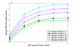
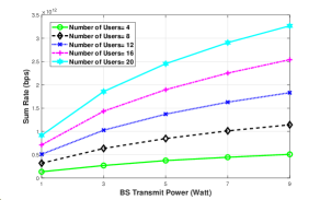
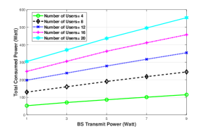
Fig. 2 illustrates the energy efficiency, sum-rate, and network-consumed-power performance of the proposed cooperative scheme with different BS transmit power levels and with different number of users in the network. The first observation here, is that as the BS transmit power increases the network EE increases then starts to saturate as can be seen in Fig. 2(a). Such a trend in the network can be justified by the following argument; the increase in the BS transmit power is reflected as (i) logarithmic increase in the network sum rate (Fig. 2(b)) and as (ii) linear increase in the total network consumed power (Fig. 2(c)). The second observation here, is that as the number of considered users in the network increases both the network EE and the users’ sum rate increase; this is evident in the EE formula (13).
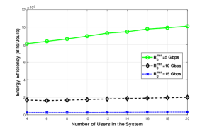
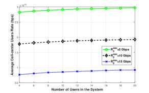
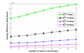
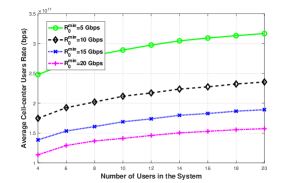
In Fig. 3(a), we present the achievable EE performance of the system while changing the minimum user required rate, Gbps. We provide this figure to support the effectiveness of the proposed cooperative scheme in improving the network EE while guaranteeing a minimum rate requirement for the cell-edge users. From this figure, one can see that as the minimum user required rate increases the network EE performance decreases; this is because with this increase in the minimum user required rate, the cooperation power at the cooperating cell-center users increases, consequently, the total consumed power in the system increases and the network EE of the system decreases. In Fig. 3(b), we provide the average cooperating cell-center users’ rate performance of the network while changing . This figure demonstrates the ability of the proposed cooperative scheme in achieving high data rate for the cooperating cell-center users, which are between - Tbps, while guaranteeing a minimum user required rate for all the cell-edge users. For benchmarking purposes, in Fig. 4, we provide the achievable EE and the average cooperating cell-center users’ rate performance of the mmWave-NOMA counterpart scheme. We assume that the mmWave carrier frequency is GHz with a contiguous bandwidth of GHz [17]. Comparing Fig. 3 with Fig. 4, it is evident that both the achievable EE and average cooperating cell-center users’ rate have a large gain as a consequence of operating in the THz band compared with the mmWave band.
V Conclusions and Future Research Directions
As both operating at the THz bands and NOMA-enabled scheme are envisioned to be among the enablers of high data-rate applications in future wireless networks, an energy-efficient scheme of multi-user indoor THz-MISO NOMA-enabled system with user-assisted cooperative side links is proposed and its performance investigated in this paper. Analog beamforming with the aid of the cosine similarity metric has been adopted to allocate cell-center users to BS THz beams, then the user-pairing problem between cooperating cell-center users and cell-edge users has been tackled through the Hungarian algorithm that pairs users based on the Euclidean distance, finally, the power allocation of the BS transmit power as well as the cooperation power of the cooperating cell-center users has been sequentially optimized. The obtained results demonstrate the energy efficiency and illustrate the effect of changing different network parameters, such as, changing the BS transmit power levels and changing cell-edge users’ minimum required rate on the EE of the network. We intend to extend this work by taking into account some practical considerations such as the performance of the proposed scheme with imperfect CSI and with NLoS scenarios.
VI Acknowledgement
This work was supported in part by the King Fahd University of Petroleum and Minerals under Grant SB191038; in part by Ericsson Canada Inc.; and in part by the Discovery Grant of the Natural Sciences and Engineering Research Council of Canada.
References
- [1] C. Han, Y. Wu, Z. Chen, and X. Wang, “Terahertz communications (TeraCom): Challenges and impact on 6G wireless systems,” arXiv preprint arXiv:1912.06040, Dec. 2019.
- [2] Z. Zhang, Y. Xiao, Z. Ma, M. Xiao, Z. Ding, X. Lei, G. K. Karagiannidis, and P. Fan, “6G wireless networks: Vision, requirements, architecture, and key technologies,” IEEE Veh. Technol. Mag., vol. 14, no. 3, pp. 28–41, Jul. 2019.
- [3] T. S. Rappaport, Y. Xing, O. Kanhere, S. Ju, A. Madanayake, S. Mandal, A. Alkhateeb, and G. C. Trichopoulos, “Wireless communications and applications above 100 GHz: Opportunities and challenges for 6G and beyond,” IEEE Access, vol. 7, pp. 78 729–78 757, 2019.
- [4] H. Sarieddeen, N. Saeed, T. Y. Al-Naffouri, and M. Alouini, “Next generation Terahertz communications: A rendezvous of sensing, imaging, and localization,” IEEE Commun. Mag., vol. 58, no. 5, pp. 69–75, Jun. 2020.
- [5] O. Maraqa, A. S. Rajasekaran, S. Al-Ahmadi, H. Yanikomeroglu, and S. M. Sait, “A survey of rate-optimal power domain NOMA with enabling technologies of future wireless networks,” IEEE Commun. Surveys Tuts., vol. 22, no. 4, pp. 2192–2235, 4nd Quarter 2020.
- [6] M. Elsayed, M. Erol-Kantarci, and H. Yanikomeroglu, “Transfer reinforcement learning for 5G-NR mm-Wave networks,” IEEE Trans. Wireless Commun., pp. 1–1, 2020.
- [7] G. Liu, F. R. Yu, H. Ji, V. C. Leung, and X. Li, “In-band full-duplex relaying: A survey, research issues and challenges,” IEEE Commun. Surveys Tuts., vol. 17, no. 2, pp. 500–524, 2nd Quarter 2015.
- [8] X. Zhang, C. Han, and X. Wang, “Joint beamforming-power-bandwidth allocation in Terahertz NOMA networks,” in Proc. 16th Annu. IEEE Int. Conf. Sens. Commun. Netw. (SECON), Jun. 2019, pp. 1–9.
- [9] H. Zhang, H. Zhang, W. Liu, K. Long, J. Dong, and V. C. M. Leung, “Energy efficient user clustering, hybrid precoding and power optimization in Terahertz MIMO-NOMA systems,” IEEE J. Sel. Areas Commun., vol. 38, no. 9, pp. 2074–2085, Sep. 2020.
- [10] S. R. Sabuj, A. M. S. Khan, and M. Hamamura, “Application of non-orthogonal multiple access for machine type communication in sub-terahertz band,” Comput. Netw., vol. 182, p. 107508, Aug. 2020.
- [11] Z. Xiao, L. Zhu, Z. Gao, D. O. Wu, and X. Xia, “User fairness non-orthogonal multiple access (NOMA) for Millimeter-Wave communications with analog beamforming,” IEEE Trans. Wireless Commun., vol. 18, no. 7, pp. 3411–3423, Jul. 2019.
- [12] S. Priebe and T. Kurner, “Stochastic modeling of THz indoor radio channels,” IEEE Trans. Wireless Commun., vol. 12, no. 9, pp. 4445–4455, Sep. 2013.
- [13] S. Al-Ahmadi, “On the achievable Max-Min rates of cooperative power-domain NOMA systems,” IEEE Access, vol. 8, pp. 173 112–173 122, 2020.
- [14] J. Tang and X. Zhang, “Cross-layer resource allocation over wireless relay networks for quality of service provisioning,” IEEE J. Sel. Areas Commun., vol. 25, no. 4, pp. 645–656, May 2007.
- [15] H. M. Al-Obiedollah, K. Cumanan, J. Thiyagalingam, J. Tang, A. G. Burr, Z. Ding, and O. A. Dobre, “Spectral-energy efficiency trade-off-based beamforming design for MISO non-orthogonal multiple access systems,” IEEE Trans. Wireless Commun., vol. 19, no. 10, pp. 6593–6606, Oct. 2020.
- [16] A. S. Rajasekaran, O. Maraqa, H. U. Sokun, H. Yanikomeroglu, and S. Al-Ahmadi, “User clustering in mmWave-NOMA systems with user decoding capability constraints for B5G networks,” IEEE Access, vol. 8, pp. 209 949–209 963, 2020.
- [17] J. Cui, Z. Ding, P. Fan, and N. Al-Dhahir, “Unsupervised machine learning-based user clustering in millimeter-Wave-NOMA systems,” IEEE Trans. Wireless Commun., vol. 17, no. 11, pp. 7425–7440, Nov. 2018.
- [18] H. W. Kuhn, “The hungarian method for the assignment problem,” Naval Research Logistics Quarterly, vol. 2, no. 1-2, pp. 83–97, Mar. 1955.
- [19] C. Lin and G. Y. Li, “Energy-efficient design of indoor mmWave and sub-THz systems with antenna arrays,” IEEE Trans. Wireless Commun., vol. 15, no. 7, pp. 4660–4672, Jul. 2016.
- [20] T. O. Olwal, K. Djouani, and A. M. Kurien, “A survey of resource management toward 5G radio access networks,” IEEE Commun. Surveys Tuts., vol. 18, no. 3, pp. 1656–1686, 3rd Quarter 2016.
- [21] J. Chen, S. Li, J. Xing, J. Wang, and S. Fu, “Multiple nodes access of wireless beam modulation for 6G-enabled internet of things,” IEEE Internet of Things Journal, pp. 1–1, 2020.
- [22] R. Singh and D. Sicker, “An analytical model for efficient indoor THz access point deployment,” in Proc. IEEE Wireless Commun. Netw. Conf. (WCNC), Jun. 2020, pp. 1–8.
- [23] I. E. Gordon, L. S. Rothman, C. Hill, R. V. Kochanov, Y. Tan, P. F. Bernath, M. Birk, V. Boudon, A. Campargue, K. Chance et al., “The HITRAN 2016 molecular spectroscopic database,” J. Quant. Spectrosc. Rad. Transfer, vol. 203, pp. 3–69, Dec. 2017.