Polar-Precoding: A Unitary Finite-Feedback Transmit Precoder for Polar-Coded MIMO Systems
Abstract
We propose a unitary precoding scheme, namely polar-precoding, to improve the performance of polar-coded MIMO systems. In contrast to the traditional design of MIMO precoding criteria, the proposed polar-precoding scheme relies on the polarization criterion. In particular, the precoding matrix design comprises two steps. After selecting a basic matrix for maximizing the capacity in the first step, we design a unitary matrix for maximizing the polarization effect among the data streams without degrading the capacity. Our simulation results show that the proposed polar-precoding scheme outperforms the state-of-the-art DFT precoding scheme.
Index Terms:
Polar-coded MIMO system, polarization criterion, precoding, unitary matrix.I Introduction
Transmit precoding (TPC) is a channel-adaptive technique of precompensating the deleterious channel effects about to be encountered based on the knowledge of channel state information (CSI) at the transmitter (CSIT) [1]. Given the limited bandwidth of control channels in practical communication systems, typically codebook-based TPC schemes relying on a low-rate CSI-feedback are used [2, 3]. The pivotal design aspects are the codebook design and the CSI-entry selection criterion. The simplest codebook design relies on selecting a specific antenna subset [4, 5]. By contrast, the Fourier codebook proposed in [6] appropriately rotates the transmit signal in a high-dimensional complex space. Furthermore, the authors of [7] and [8] transform the codebook design into packing subspaces into the Grassmann manifold relying on the projection two-norm and Fubini-Study distances, respectively. As for the CSI selection criterion, the popular capacity criterion or the maximum-likelihood (ML) criterion [8] may be used for selecting the TPC matrix from the codebook. However, these codebooks and their selection criteria were designed for uncoded MIMO systems with an emphasis on the MIMO detection performance. In reality, coded MIMO systems have to be used, where we focus on the performance of the decoded bits.
In this context, the polar-coded MIMO (PC-MIMO) systems proposed by Dai et al. [9] have been shown to closely approach the capacity of MIMO system with the aid of successive interference cancellation (SIC), outperforming their turbo/LDPC-coded MIMO counterparts. The PC-MIMO system of [9] was designed for fast-fading channels without exploiting the CSIT. However, harnessing the knowledge of CSIT is capable of further improving the performance. Since the polarization effect of data streams is an important factor influencing the performance [9], the PC-MIMO TPC should be designed on the basis of explicitly exploiting the polarization effect.
Table I boldly contrasts our novel contributions to the state-of-the-art both in terms of the selection criterion and the polarization effect, showing the novelty of this work explicitly. The polarization effect is introduced by the successive cancellation (SC) structure. The bit-polarization was first proposed by Arıkan [10] for designing polar codes. Then, the bit-polarization was extended to symbol polarization and a -ary multilevel polar-coded modulation scheme was proposed in [11]. Furthermore, Dai et al. designed the PC-MIMO [9] using antenna polarization. Inspired by these papers, we conceive data stream polarization to design a unitary precoding scheme.
| 2004[4, 5] | 2005[7] | 2005[8] | 2009[10] | 2013[11] | 2018[9] | 2020[16] | This work | |
| SNR criterion | ✓ | ✓ | ||||||
| ML criterion | ✓ | ✓ | ||||||
| Capacity criterion | ✓ | ✓ | ||||||
| Polarization criterion | ✓ | |||||||
| Bit polarization | ✓ | ✓ | ✓ | ✓ | ✓ | |||
| Symbol polarization | ✓ | ✓ | ||||||
| Antenna polarization | ✓ | ✓ | ||||||
| Data stream polarization | ✓ |
In this compact letter, a unitary polar TPC is proposed for improving the performance of PC-MIMO systems. Since the polarization of the substreams directly affects the PC-MIMO performance [9], the proposed polar TPC scheme stems from the polarization criterion used for maximizing the polarization effect, which constitutes a radical departure from the traditional TPC design. Given the codebook, the TPC matrix selection comprises two steps. In the first step, a basic TPC matrix is selected for maximizing the capacity. In the second step, we post-multiply the basic matrix by a unitary matrix, which is specifically designed for maximizing the polarization of substreams without eroding the capacity optimized by the basic TPC matrix. Moreover, the optimal polar TPC of the PC-MIMO system is derived under the polarization criterion and a method to design the polar TPC codebook is proposed based on the DFT TPC. Our simulation results illustrate that the proposed polar TPC scheme outperforms the state-of-the-art DFT TPC scheme.
Notational Conventions: In this letter, scalars are denoted by the lowercase letters (e.g., ). The calligraphic characters, such as , are used to denote sets. The bold capital letters, such as , denote matrices. The -th column of matrix is written as and represents the matrix . The element in the -th row and the -th column of matrix is written as . and are used to denote the transposition and the conjugate transposition of , respectively. The bold lowercase letters (e.g., ) are used to denote column vectors. Notation denotes the column subvector and denotes the -th element of . Given an index set , is a subvector composed of , . We use to denote the set of matrices with orthonormal columns, to denote an identity matrix, to denote the -th smallest singular value of and to denote an diagonal matrix. Throughout this letter, means “base 2 logarithm”.
II Preliminaries
II-A Polar-Coded MIMO System
In this section, we introduce the PC-MIMO system of [9] by intrinsically amalgamating it with a unitary TPC scheme. The information bits are first encoded and modulated into QPSK symbols, which are then precoded by the codebook and transmitted via the MIMO channel using -transmit antennas, -receive antennas and bitstreams within time slots. We focus on block-fading channels, where the channels remain constant for time slots.
At the transmitter, the source sequence composed of and with information set and code rate is demultiplexed into different bitstreams and each bitstream is fed into a polar encoder. Then, the -dimensional encoded sequence , , is mapped into an -dimensional modulated sequence using QPSK modulation. Next, the symbol matrix is multiplied by a TPC matrix and produces the transmit signal matrix , where is the total transmit energy. Hence, the received signal matrix at the output of block fading channels is
| (1) |
where is the channel response matrix having i.i.d entries in and the elements of are i.i.d. complex circular Gaussian random variables with . Perfect channel estimation is assumed at the receiver. To simplify the analysis, we rewrite the system model (1) by omitting the time slot as
| (2) |
At the receiver, a joint multistage detection and decoding receiver is used, which is similar to the SC decoding rules of polar codes [10, 12, 13]. Hence, other SC-like decoding schemes, such as the successive cancellation list (SCL) decoder [14, 15, 16], the successive cancellation stack decoder [17, 18] and the CRC-aided SCL (CA-SCL) decoder [19], can also be used in the PC-MIMO system to improve the performance. The MIMO detection order proceeds from substream to . A substream is first demodulated into bit log-likelihood ratios (LLRs) and the LLRs are then fed into the polar decoder. Then, the decoded bitstream is entered into the polar encoder to retrieve the QPSK symbols. After the bits in the substream have been estimated, they are fed back to the MIMO detector in order to perform interference cancellation.
II-B Unitary Precoding
The receiver selects a TPC matrix from the codebook set with , where and bits of feedback are available. The DFT-based TPC designed for spatial multiplexing systems in [7, 6] is formulated as:
| (3) |
where the entry of at is and is the diagonal matrix
| (4) |
In (4), the vector is:
| (5) |
where and . Then, random testing of the values of is used to optimize the cost function for training the codebook.
The capacity maximization criterion is used to select the TPC matrix from yielding:
| (6) |
where is the capacity of the unitary TPC-aided system.
III Polar Precoding
In this section, we first illustrate the polarization effect of substreams. Then, the polarization criterion is provided and the optimal unquantized TPC satisfying this criterion is derived. Finally, the method of designing the polar TPC codebook is proposed.
III-A Polarization Effect of Substreams
Given , the system model (2) is simplified to
| (7) |
Then, due to the SC structure at the receiver, the system model associated with the -st to the -st substreams known is formulated as:
| (8) |
According to the chain rule of mutual information, the capacity of the PC-MIMO system is decomposed into
| (9) |
and is the capacity of the -th substream with SC structure, which is calculated by
| (10) | ||||
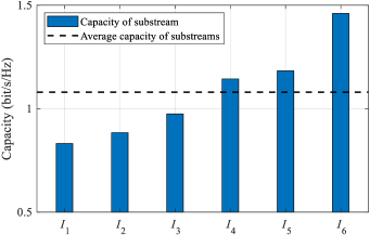
Similar to [10, 9], the SC structure also introduces the polarization effect of substreams, i.e., the capacity difference among . Fig. 1 is an example illustrating the polarization effect for , and at dB using DFT TPC. In Fig. 1, the capacities of the substreams are increasing from to . Based on that, , and are lower than the average capacity and , and are higher than the average capacity. Thus, a capacity difference occurs among to and the polarization effect is introduced by the SC structure.
III-B Polarization Criterion
In PC-MIMO systems, drastic polarization leads to better performance when the capacity is identical [9]. Thus, maximizing the system capacity
| (11) |
and simultaneously maximizing the polarization effect among the substreams
| (12) |
are both necessary for our polar TPC, where is the average capacity of the substreams, i.e., . However, it is a challenge to directly find a suitable satisfying both (11) and (12).
Then, since remains unchanged when is multiplied by a unitary matrix, is partitioned into two matrices and , and we have
| (13) |
where .
Based on (13), we can find a matrix for maximizing , which is equivalent to maximizing . When is determined, remains unchanged for . Thus, can be used for maximizing the polarization effect without affecting the system capacity. Hence, can satisfy both (11) and (12). The polarization criterion is defined as
| (14) |
where and are the codebooks for and , respectively.
III-C Optimal Unquantized TPC
According to the polarization criterion, the system model (2) is transformed into
| (15) |
Let the singular value decomposition of a matrix be given by
| (16) |
where and are unitary matrices and is a diagonal matrix with denoting the -th smallest singular value of at entry .
Then, based on (15), we first derive that maximizes the polarization effect with .
Lemma 1.
The optimal TPC matrix with is .
Proof:
For the system model (8), we have . In [8], it has been proved that can maximize , where is a matrix constructed from the last columns of . Thus, maximizes .
Let denote the capacity of the -th substream optimized by and . We transform the proof into linear programming as follows:
| (17) | ||||
Then, since is a convex function, the maximum value is on the boundary and the point is , . Thus, is the optimal TPC matrix with . ∎
According to Lemma 1, we can readily derive the optimal TPC matrix for satisfying the polarization criterion.
Lemma 2.
The optimal TPC matrix is a matrix constructed from the last columns of .
III-D Polar TPC Codebook Design
The codebook of the polar TPC is with , , and . The codebook design is divided into two steps, which are summarized as follows:
- 1.
-
2.
is also designed by the DFT TPC, i.e.,
(21) Hence, the entry of at is and the diagonal matrix is
(22)
For polar TPC, the optimization of and is important. In this paper, and are selected empirically and we just provide a compact insight into the optimization. According to the polarization criterion (14), and affect the capacity and the polarization effect, respectively. Then, a higher or a lower leads to higher capacity and lighter polarization effect, and vice versa. Explicitly, both factors have an influence on the PC-MIMO performance. Thus, the polar TPC codebook has to strike a trade-off between the capacity and the polarization effect, and both as well as should be optimized.
IV Performance Evaluation

In this section, we first provide the capacity of the substreams for the fixed channel matrix
| (23) |
Then, the block error rate (BLER) performance of the proposed polar TPC is provided for the channel response in (23). Finally, we provide the BLER performance of polar TPC under block-fading channels. The PC-MIMO system is constructed by the Gaussian approximation (GA) [20]. The polarization criterion maximizes both the capacity and the polarization effect simultaneously. To allow the system performance approach the capacity, ML detection is considered. Furthermore, since the polarization effect is catalyzed by the SIC structure of the PC-MIMO system, ML-SIC detection is used in this paper.
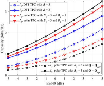
Fig. 2 shows the capacity of the substreams for different TPC schemes and for the fixed channel response in (23), where , and . In Fig. 2, and are the capacities of the first and the second substreams, respectively. We can observe that by introducing the TPC matrix , the polarization effect of the polar TPC for and is higher than that of the DFT TPC with . Thus, the proposed polar TPC enhances the polarization effect among the substreams, which improves the BLER of the PC-MIMO system shown in Fig. 3. Then, the polar TPC using the optimal TPC also shows more significant polarization effect compared to the polar TPC with and . Similarly, the more significant polarization effect improves the BLER in Fig. 3 as well.
Fig. 3 illustrates the BLER of PC-MIMO systems for different TPC schemes, where , , , and . ML-SIC detection and SC decoding are used for the PC-MIMO system. Then, in order to make the comparison fair, the performance of the DFT and polar TPCs having identical number of feedback bits is provided, i.e., for the DFT TPC, and as well as for the polar TPC. In Fig. 3, we can first observe that the GA bound, widely used in [9, 20], is still an upper bound of the performance of PC-MIMO TPC schemes under SC decoding. Moreover, the GA bound coincides with the corresponding BLER performance in the high signal-to-noise ratio (SNR) regions. Furthermore, as expected, both the DFT and the polar TPCs outperform the “no-TPC” system. Hence, TPC efficiently improves the performance of PC-MIMO. Additionally, since the proposed polar TPC has better polarization effect than the DFT TPC, it has about dB performance gain at BLER . Moreover, due to the better polarization effect shown in Fig. 2, the performance of the polar TPC relying on the optimal TPC achieves about dB gain over the polar TPC with and at BLER . Therefore, better polarization leads to a better PC-MIMO performance using the proposed polar TPC instead of other known TPCs.
Fig. 4 provides the BLER of PC-MIMO systems using CA-SCL decoding [19] and polar TPC under block-fading channels, where , , , and . The ML-SIC MIMO detection is used and the list size of the CA-SCL decoder is 8, where the 6-bit CRC of [21] is used. In Fig. 4, the performance of the polar TPC using the optimal TPC is provided, which can be treated as the best-case bound of the polar TPC, since maximizes the polarization effect of polar TPC. Then, we can observe that the performance of polar TPC using limited feedback is close to the performance of polar TPC using as increases. Specifically, the polar TPC using and has almost identical BLER to that of in the high SNR regions. Thus, the polar TPC has the potential of approaching the optimal performance, despite of limited feedback.
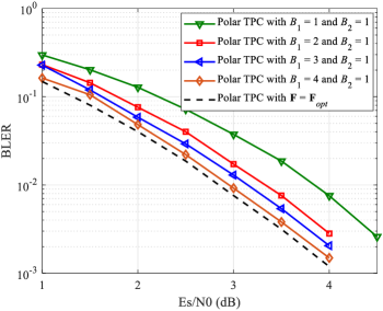
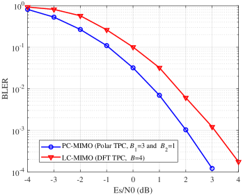
Fig. 5 and Fig. 6 portray out BER and BLER performance comparisons, respectively, where we have , , , and . For the PC-MIMO system, the CA-SCL decoder having a list size of 8 and 6-bit CRC [21] is used, where the MIMO detector is ML-SIC. For the low-density-parity-check (LDPC)-coded MIMO (LC-MIMO) system, the LDPC encoder and the rate-matching algorithm are those of 5G [21], the sum-product algorithm having 25 iterations and layered scheduling are used for the LDPC decoder [22], and the MIMO detector uses the linear minimum mean square error (LMMSE) algorithm. In Fig. 5 and Fig. 6, we can observe that the PC-MIMO system using polar TPC has better BER and BLER performance than the LC-MIMO system associated with DFT TPC. Specifically, at BER and BLER , the PC-MIMO system has 1.6dB and 1.1dB performance gain over the LC-MIMO system, respectively.
Since the codebook is designed offline, selecting an appropriate precoding matrix from the codebook dominates the complexity of precoding. The complexity of calculating the capacity is on the order of . Hence, the complexity of the DFT TPC relying on the capacity criterion is . For polar TPC, the complexities of selecting and are and , respectively. Then, the complexity of polar TPC is .

V Conclusion
In this compact letter, we proposed the polar TPC of PC-MIMO systems relying on the new polarization criterion, which is quite different from other design criteria. Based on this new polarization criterion, the optimal TPC was derived and the method of designing the polar TPC codebook was proposed. The simulation results illustrate that the proposed polar TPC outperforms its DFT-based counterpart.
References
- [1] D. Tse and P. Viswanath, Fundamentals of Wireless Communications. Cambridge, U.K.: Cambridge Univ. Press, 2005.
- [2] 3GPP TS 36.211 V10.0.0, Physical channels and modulation (Release 10), Dec. 2010.
- [3] 3GPP TS 38.211 V16.3.0, Physical channels and modulation (Release 16) , Sep. 2020.
- [4] A. F. Molisch and M. Z. Win, “MIMO systems with antenna selection,” IEEE Microwave Magazine, vol. 5, no. 1, pp. 46–56, March 2004.
- [5] S. Sanayei and A. Nosratinia, “Antenna selection in MIMO systems,” IEEE Communications Magazine, vol. 42, no. 10, pp. 68–73, Oct. 2004.
- [6] B. M. Hochwald, T. L. Marzetta, T. J. Richardson, W. Sweldens and R. Urbanke, “Systematic design of unitary space-time constellations,” IEEE Trans. Inf. Theory, vol. 46, no. 6, pp. 1962–1973, Sept. 2000.
- [7] D. J. Love and R. W. Heath, “Limited feedback unitary precoding for orthogonal space-time block codes,” IEEE Trans. Sig. Proc., vol. 53, no. 1, pp. 64–73, Jan. 2005.
- [8] D. J. Love and R. W. Heath, “Limited feedback unitary precoding for spatial multiplexing systems,” IEEE Trans. Inf. Theory, vol. 51, no. 8, pp. 2967–2976, Aug. 2005.
- [9] J. Dai, K. Niu and J. Lin, “Polar-coded MIMO systems,” IEEE Trans. Veh. Technol., vol. 67, no. 7, pp. 6170–6184, July 2018.
- [10] E. Arıkan, “Channel polarization: A method for constructing capacity achieving codes for symmetric binary-input memoryless channels,” IEEE Trans. Inf. Theory, vol. 55, no. 7, pp. 3051–3073, Jul. 2009.
- [11] M. Seidl, A. Schenk, C. Stierstorfer and J. B. Huber, “Polar-coded modulation,” IEEE Trans. Commun., vol. 61, no. 10, pp. 4108–4119, Oct. 2013.
- [12] Z. Babar et al., “Polar codes and their quantum-domain counterparts,” IEEE Commun. Surv. Tutor., vol. 22, no. 1, pp. 123–155, Firstquarter 2020.
- [13] Z. B. Kaykac Egilmez, L. Xiang, R. G. Maunder and L. Hanzo, “The development, operation and performance of the 5G polar codes,” IEEE Commun. Surv. Tutor., vol. 22, no. 1, pp. 96–122, Firstquarter 2020.
- [14] I. Tal and A. Vardy, “List decoding of polar codes,” IEEE Trans. Inf. Theory, vol. 61, no. 5, pp. 2213–2226, May. 2015.
- [15] K. Chen, K. Niu, and J. R. Lin, “List successive cancellation decoding of polar codes,” Electron. Lett., vol. 48, no. 9, pp. 500–501, 2012.
- [16] L. Xiang, Y. Liu, Z. B. K. Egilmez, R. G. Maunder, L. -L. Yang and L. Hanzo, “Soft list decoding of polar codes,” IEEE Trans. Veh. Technol., vol. 69, no. 11, pp. 13921–13926, Nov. 2020.
- [17] K. Chen, K. Niu and J. Lin, “Improved successive cancellation decoding of polar codes,” IEEE Trans. Commun., vol. 61, no. 8, pp. 3100–3107, Aug. 2013.
- [18] L. Xiang, S. Zhong, R. G. Maunder and L. Hanzo, “Reduced-complexity low-latency logarithmic successive cancellation stack polar decoding for 5G new radio and its software implementation,” IEEE Trans. Veh. Technol., vol. 69, no. 11, pp. 12449–12458, Nov. 2020.
- [19] K. Niu and K. Chen, “CRC-aided decoding of polar codes,” IEEE Commun. Lett., vol. 16, no. 10, pp. 1668–1671, Oct. 2012.
- [20] P. Trifonov, “Efficient design and decoding of polar codes,” IEEE Trans. Commun., vol. 60, no. 11, pp. 3221–3227, Nov. 2012.
- [21] 3 Generation Partnership Project (3GPP), “Multiplexing and channel coding,” 3GPP TS 38.212 V15.0.0, 2017.
- [22] S. Lin and D. J. Costello, Error Control Coding, 2nd ed. Englewood Cliffs, NJ, USA: Prentice-Hall, 2004.