Experimental Demonstration of RAN Functional Split over virtual PON Transport Network
Abstract
Cloud-Radio Access Networks (Cloud-RANs) are separating the mobile network’s base station functions into three units, the connection between the two of them is referred to as the fronthaul network. This work demonstrates the transmission of user data transport blocks between the distributed Medium Access Control (MAC) layer and local Physical (PHY) layer in the radio unit over a Passive Optical Network (PON). PON networks provide benefits in terms of economy and flexibility when used for Cloud-RAN fronthaul transport. However, the PON upstream scheduling can introduce additional latency that might not satisfy the requirements imposed by Cloud-RAN functional split. In this work we demonstrate how our virtual Dynamic Bandwidth Allocation (DBA) concept can be used to effectively communicate with the mobile Long Term Evolution (LTE) scheduler, adopting the well known cooperative DBA mechanism, to reduce the PON latency to satisfactory values. Thus, our results show the feasibility of using PON technology as transport medium of the fronthaul for the MAC/PHY functional split, in a fully virtualised environment. Further background traffic is added, so that measurements show a more realistic scenario. The obtained round trip times indicates that using PON at fronthaul might be limited to the distance of km for a synchronised scenario, or no compliance for an non-synchronised scenario.
- AON
- Active Optical Network
- BBF
- BroadBand Forum
- BBU
- Base Band Unit
- BMap
- Bandwidth Map
- CO
- Central Office
- CORD
- Central Office Rearchitected as a Data Centre
- C-RAN
- Cloud Radio Access Network
- CU
- Centralised Unit
- DBA
- Dynamic Bandwidth Allocation
- DBRu
- Dynamic Bandwidth Report upstream
- DPDK
- Data Plane Development Kit
- DSL
- Digital Subscriber Line
- DU
- Distributed Unit
- EAL
- Environment Abstraction Layer
- FCC
- Federal Communications Commission
- FTTH
- Fiber-to-the-Home
- HARQ
- Hybrid Automatic Repeat Request
- KPI
- Key Performance Indicator
- InP
- Infrastructure Provider
- L2
- Layer-2
- L3
- Layer-3
- LTE
- Long Term Evolution
- MAC
- Medium Access Control
- NGA
- Next Generation Access
- ODN
- Optical Distribution Network
- OLO
- Other Licensed Operator
- OLT
- Optical Line Terminal
- ONU
- Optical Network Unit
- QoS
- Quality of Service
- PBMA
- Priority Based Merging Algorithm
- PON
- Passive Optical Network
- R-CORD
- Residential CORD
- RRU
- Remote Radio Unit
- RU
- Radio Unit
- SLA
- Service Level Agreement
- SRI-OV
- Single Root Input/Output Virtualization
- TDM
- Time Division Multiplexing
- T-CONT
- Transmission Container
- UE
- User Equipment
- URLLC
- Ultra Reliable Low Latency Communications
- vDBA
- virtual DBA
- VM
- Virtual Machine
- VNF
- Virtual Network Function
- VNO
- Virtual Network Operator
- vOLT
- Virtual OLT
- VULA
- Virtual Unbundled Local Access
- XG-PON
- 10 Gigabit PON
- XGS-PON
- 10 Gigabit per second Symmetrical PON
I Introduction
Cloud-Radio Access Network (Cloud-RAN) is a promising technology that is able to scale and enhance network efficiency to support new features over the next several years by means of centralisation. In Cloud-RAN architecture, baseband functions are centrally deployed providing several benefits in terms of offering high level of cooperation between base stations and facilitating RAN sharing. These aspects allow dynamic reconfiguration of resources enabling to fulfil diverse requirements of various vertical industrial applications. Cloud-RAN significantly benefits from the emerging technologies such as softwarisation and virtualisation. Softwarisation/virtualisation within Cloud-RAN allows adaptive allocation of RAN functions between components of Cloud-RAN introducing the so-called flexible functional split. Flexible functional split typically offer flexibility and adaptability in the Cloud-RAN, thus, enabling to deliver services with diverse requirements. In NGMN [1], Cloud-RAN is composed of Central Unit (CU), Distributed Unit (DU) and Radio Unit (RU). The communication link between CU and DU is called midhaul, and between DU and RU is called fronthaul. NGMN proposed different allocations of the baseband functions between the three components. In particular, it defined a high layer split (HLS) and a low layer split (LLS), each of them have different communication performance requirements. In this paper, we consider LLS, specifically Medium Access Control/Physical layer (MAC/PHY) split.
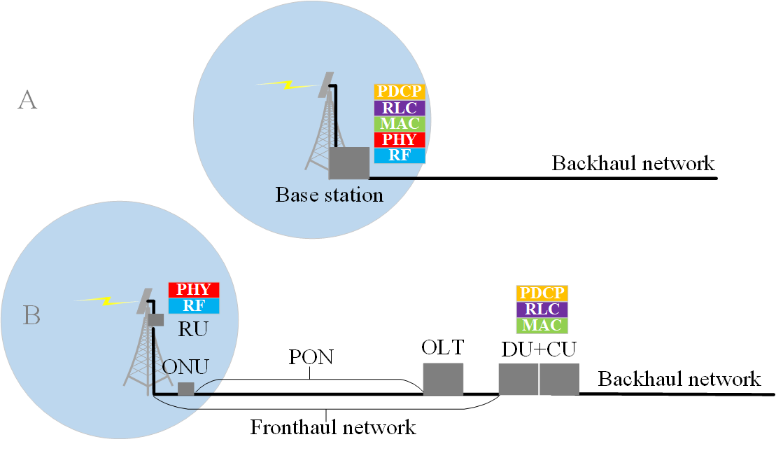
Different solutions exist for LLS transport interface (fronthaul). The benefits of the fiber fronthaul network, if available, are multiple folds and includes a longer transmission range, a low loss transmission medium and the opportunity of very high transmission capacity. Given the high cost of fiber deployments, research is looking into the use of fibers that have already been installed for other purposes, and investigates how the fronthaul network can co-exist with other demanding applications. A network technology widely deployed for fiber to the home (FTTH) solutions is Passive Optical Network (PON) [2].
The PON network consists of one or multiple Optical Network Units connected to one Optical Line Terminal (OLT). Figure 1A illustrates the traditional base station ( the Distributed RAN - D-RAN) and Figure 1B illustrates Cloud-RAN with MAC/PHY functional split transported over a PON fronthaul. In a PON network, multiple technologies can be multiplexed leaving the opportunity of connecting multiple RUs with different functional splits and both constant and variable fronthaul bit rate [3]. Nevertheless, PON has one problem when acting as a fronthaul network; the mechanism that guarantees dynamic and exact scheduling of upstream resources between the OLT and every ONU is based on DBA. DBA ensures high bandwidth utilization but requires the ONU to request bandwidth at the OLT before each upstream transmission [3]. This work aims at overcoming this challenge by presenting an optimised DBA solution, referred to as the cooperative DBA, whereby bandwidth allocation in PON is requested when upstream scheduling information is sent to the UE. With this solution, we demonstrate the feasibility of transporting the MAC/PHY split over an 10 Gigabit per second Symmetrical PON (XGS-PON) fronthaul network using a hardware-based test-bed.
This paper is organized as follows: Section II provides an overview of the status of current work in the area of PON fronthauling. Section III introduces the XGS-PON fronthaul. Section IV presents the test-bed used for measurements in this work. Section V propounds the first round of feasibility studies. Section VI propounds extended studies where background traffic is included and compares the cooperative DBA scenario to the original non-synchronised scenario. Finally section VII concludes the paper.
II State of the art
Recent studies have looked into the idea of using PON as the fronthaul network for Cloud-RAN. One of the first works considering PON fronthaul is found in [4], which states the economical benefits of using PON fronthaul for small cells. The work in [4] introduces the concept of using mobile upstream scheduling information for reduction of Round Trip Time (RTT) delay. The work in [4] considers a simple functional split with only the RF part in the RU, and the PHY and upper transmission processing in the CU. The concept of this current work relies on the work in [3] where the authors present an optical-mobile cooperation interface converting mobile upstream scheduling information to transmit request information for the PON. The idea is to transmit the request information to the OLT directly from the CU. In [3] the actual functional split used for the measurements is not specified, but the paper states the benefits of a packet switched fronthaul network. The work in [3] extends the conversion process to handle multiple input frames and considers multiple RUs. In [5], the authors demonstrate a simulated transmission of PHY functional split over PON. In [6] the PON fronthaul is used as a variable rate fronthaul for the functional split with the lowest number of functions in the RU, having a constant fronthaul bit rate. Using a software defined network controller, the cell bandwidth and consequently the fronthaul bit rate is dynamically changed. In [7] the variable-rate PON fronthaul is experimentally demonstrated.
Some of the authors of this current work have in [8] experimented with transport of transport blocks between the PHY in the RU and the MAC in the CU over an Ethernet fronthaul network. The same test-bed transporting MAC/PHY split transport blocks over Ethernet is further investigated in [9] for Ultra Reliable Low Latency Communications (URLLC) scenarios. The work in [10] presents a model deriving the achievable latency for a PON fronthaul and the maximum number of connected RUs. This model forms the basis of the latency calculations in this work. For a comprehensive overview of all functional splits is referred to [11]. Regarding the MAC/PHY functional split, NGMN defines this interface location more specifically as between the MAC and the Forward Error Correction (FEC) in the PHY [12]. When using the MAC/PHY functional split, transport blocks are transferred over the fronthaul network [11]. These transport blocks have been through the physical layer processing which means the upstream signal is, among other processes, de-mapped, demodulated an de-scrambled before transmission [11]. The MAC/PHY functional split is defined by NGMN as one of the converging options for LLS [13]. Multiple options for LLS are being developed in parallel providing different split options to support different use cases [13]. The MAC/PHY functional split is beneficial in use cases requiring a low fronthaul bit rate and a centralised scheduler coordinating the available resources [11]. The MAC/PHY functional split has time critical functions located in the DU+CU and this puts stringent requirements on the fronthaul latency [11]. NGMN [12] defines a maximum one-way latency of 250 us, which is at the protocol stack level.
III The XGS-PON Fronthaul
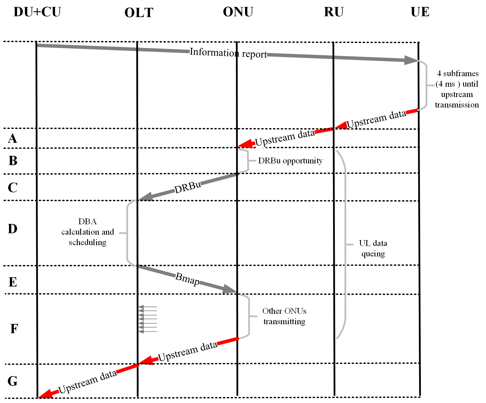
The type of PON we use in this work is XGS-PON [14]. In a PON, the OLT handles the traffic management and in the downstream direction, the OLT transmits data to the ONU while being aware of the quality of service. In the upstream direction, the user sends data to the ONU and the ONU stores the data in a queue until it can be forwarded. When the ONU receives the user data it sends a DRBu message to the OLT requesting bandwidth allocation for the specific queue size. The OLT will then reply with a Bandwidth Map (BMap) message containing the start time and grant size. The upstream data is thereby delayed while it waits in the ONU’s queue. This delay is dependent on the transmission delay between the ONU and OLT, and the time it takes for the OLT to calculate the bandwidth assignment for the grant.
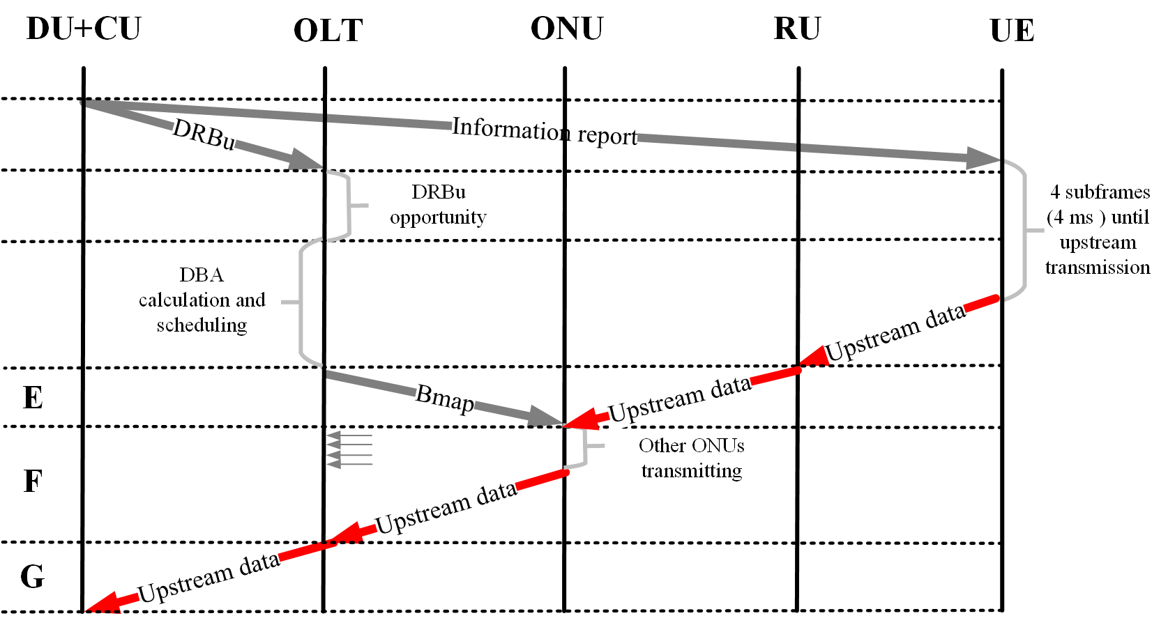
(b) The cooperative DBA solution of PON fronthaul. In the figure the latency parameters are grouped into sections, showing that compared to figure 2, then this scenario have much less latency intervals.


The delay from waiting in the ONU queue is normally not a problem when considering FTTH solutions suited to domestic and business applications, for instance Video, Voice and Data traffic. However the timing constraints to carry mobile networks, such as LTE and 5G are much more time critical. In [12] NGMN is recommending a maximum one-way latency of 250 us which we consider for our analysis. This gives a maximum RTT of 500 us for the PON fronthaul transmission.To reduce latency on the fronthaul for upstream transmission, this work makes use of the concept from [3], called Cooperative DBA, recently standardised in [15], where the DU+CU, instead of the ONU, sends the DRBu message to the OLT. This solution is possible because in mobile networks an information report is created in the upper layers of the protocol stack, informing the UE of how many Transport Blocks (TBs) are allocated to the specific transmission. This cooperative DBA scenario is illustrated in figure 2(b). The un-synchronised scenario, where there is no cooperation between PON an LTE, is illustrated in 2(a). In this work, the data from the information report is converted to a Dynamic Bandwidth Report upstream (DBRu) message inside the DU+CU, and sent from the DU+CU to the OLT, straight after the information report is sent. This way, the ONU will receive the BMap message earlier in the process and this will reduce the time spend by the user data in the ONU queue. Also, when the UE receives the information report, it triggers an uplink transmission in 4 sub-frames later.
The delay budget for the un-synchronised scenario is divided into six intervals, illustrated in figure 2(a):
- 1.
-
2.
Wait for DRBu upstream opportunity delay, because the DBRu is piggy backed into the current data transmission opportunity. The maximum delay is one frame.
- 3.
- 4.
- 5.
- 6.
- 7.
The total latency for the un-synchronised upstream transmission includes all intervals, illustrated in equation 1:
| (1) |
The total latency for the cooperative DBA upstream transmission includes only intervals E, F and G, illustrated in equation 2:
| (2) |
IV Test-bed setup
Figure 1B represents a logical overview of the test-bed setup. The RU contains the radio frequency component and the physical layer. In our test-bed implementation, the whole PON fronthaul network is collocated with the DU+CU on the same server, as illustrated in figure 3. The XGS-PON is a virtualised system, in that the key functionality related to the data plane transmission is rendered in software. In the upstream, data is packetised and Time Division Multiplexing (TDM) multiplexed in a transmission path scheduled by a DBA scheduler. This means that only one ONU can transmit at a time. In the downstream, data is instead transmitted over a continuous frame and is broadcast from the OLT to each ONU. Outwardly, from the perspective of the LTE application, the virtual XGS-PON appears as an operating system level network interface on the servers for the DU+CU and the RU. Upstream traffic enters a buffer, which is gated by a DBA client controller. The DBA client controller reports the number of bytes in the buffer, also called the Buffer Occupancy, to the DBA master. The DBA master collects the Buffer Occupancy reports from the total number of Transmission Containers and applies a DBA algorithm to decide the allocation start and stop time for each T-CONT.
The XGS-PON emulates the characteristics of the delay budget outlined in figure 2(a) for both un-synchronised and cooperative DBA scenarios. In order to make the scenarios more realistic, we apply background loading to the XGS-PON in section VI. This has the effect of inducing packet loss, jitter and latency on the foreground LTE traffic of interest. For our emulation, the upstream LTE traffic of interest as well as other similar LTE traffic is marked as high priority traffic (that is Traffic Class 4) and makes up to 60% of the upstream traffic. Other lower priority traffic (Traffic Classes 1,2 and 3) makes up the remainder (40%) of the upstream traffic. The authors in [16] analysed how different mixes of upstream traffic priorities affect each other.
The physical setup is illustrated in figure 3. The User Equipment (UE) is a LTE UE based on Open Air Interface (OAI) [17] software further described in [8]. The UE server is connected to an Universal Software Radio Peripheral (USRP) B210 via an USB3 connection. The USRP is connected via a SubMiniature version A (SMA) cable to another USRP connected to the RU server. On the RU server is all radio frequency and physical layer processing taking place. The RU server is connected to the DU+CU server via an Ethernet cable. The DU+CU server contains both the virtual XGS-PON network and the DU+CU. Entering the DU+CU server the Ethernet packets are sent to the ONU. In the ONU, the Ethernet packets are encapsulated in PON T-CONTs for transmission over the XGS-PON. First they are queued, waiting for the OLT to transmit the BMap. When this is received, the traffic containers are virtually transmitted to the OLT where they are unpacked to Ethernet frames and sent to the DU+CU. In the DU+CU the MAC and further baseband processing takes place. The DU+CU also creates DRBu messages based on information reports.
Figure 4 shows how the RTT is measured from the RU to the CU and back. RTT is used because it is a more accurate means of measurement in this specific test setup, when compared to one-way latency.
In our test-bed configuration, we implement three scenarios. Firstly, we implement a scenario where the XGS-PON operates unaware of the higher level LTE application. In particular, the upstream XGS-PON and LTE MAC schedulers operate independently of each other, referred to as the un-synchronised scenario.
Secondly, we implement the cooperative DBA scenario, where the DU+CU issues the information report or DRBu message to the DBA manager, which preemptively allocates the bandwidth to the T-CONT handling the upstream LTE traffic. This is referred to as the cooperative DBA scenario.
Thirdly we introduce the near ideal scenario, where LTE traffic is prioritised to reduce latency as much as possible. In theory, the upstream latency can be reduced to just upstream fibre transmission plus some opportunity delay, of around 35 usec on a 5 km fibre. Firstly, when the UL data arrives at the ONU, it is scheduled to take the best available slot, without waiting for the next PON frame. Secondly, because the LTE scheduler information is made available in advance, the transmission of the (n)th UL data frame can be predicted by from the timing of the (n-1)th dbru indicator from the LTE mac layer.
| Parameter | Value |
|---|---|
| Carrier Frequency | 2.68 GHz [8] |
| System bandwidth | 5 MHz [8] |
| Frame type | FDD [8] |
| # Upstream Tx/Rx antennas | 1 / 1 [8] |
| Tx Gain | 100 [8] |
| Rx Gain | 80 [8] |
| XGS-PON max transmission speed | 10 Gbps |
| Fibre transmission latency of PON | 5 uSec/km |
| Upstream Scheduling Delay, worst case (E) | 15 uSec [16] |
V Feasibility studies
First we demonstrate the feasibility of transporting the MAC/PHY functional split over the XGS-PON network using the cooperative DBA scenario. The physical and emulation parameters for the test setup are stated in table I. Figures 5 to 6(b) illustrate the feasibility of this goal, where the length of the XGS-PON network is one km.
Figure 5 shows the RTT latency measured for different packet sizes between 105 B and 585 B. The tendency shows a slight increase in RTT latency when packet sizes are growing. In figure 5, the average RTT is illustrated by columns and the lines shows the minimum and maximum RTTs. In general the smaller packets have larger fluctuations, but their average RTT is still low. The RTT measurements show how the average latency is compliant with the NGMN requirements stated in section III of 500 us. We believe this is caused by the variability on the UDP socket timing, which operates the functional split. This could be significantly reduced in the future by optimising the packet transfer process across functions. The maximum packet size measured is 585 B, which is due to upstream modulation restrictions in the OAI test-bed.
However, from Figure 6(a), which illustrates the RTT latency probability density function, we see that most transmissions are less than 150 us. The figure shows how a deviation occurs when the packet size is larger. Most of the different packet sizes have the highest probability for a RTT between 100 us and 150 us, which is still far below the NGMN threshold.
Figure 6(b) illustrates the probability density distribution of the jitter, which is another limiting parameter for the MAC/PHY functional split. In this setup, which is a combination of Ethernet and virtual PON transmission, the data is transmitted in both Ethernet packets and virtual PON T-CONTs. This setup might induce some jitter due to synchronisation ad conversion between the different transport networks.
The tendency shows how larger packet sizes have more probability for jitter, where the jitter in the smaller packets span over a longer period. Though figure 6(b) states that the jitter occurring is mainly below 20 us.


VI Comparisons of different scenarios
In this section the background traffic introduced in section IV is included in the measurements in order to make the scenarios more realistic. The measurements were performed for different lengths of the XGS-PON fronthaul ranging from 5 km to 30 km. Results are illustrated in figures 7(a), 7(b), respectively, for the jitter and RTT for increasing value of fronthaul distance. The figures illustrates the large difference between the three scenarios and how the RTT increases by the length of the fronthaul. The figure is only containing measurements for packet size 141 B. In the figures we can see that the un-synchronised scenario allows successful transmission up to 10 km distance, the cooperative DBA up to 20km and the near ideal scenario up to 25km.
While we found that transmissions could still work for latency up to 600 us, the NGMN [12] recommends a maximum one-way transport latency of 250 us, and the test-bed only measures timing in RTT, we assume the RTT threshold to be 500 us. The NGMN transport latency includes: UE processing time, eNodeB processing time and propagation time [12]. However the RTT measured in our test-bed only includes eNodeB processing time and propagation time. Figure 8 illustrates the NGMN margin times for different PON fronthaul lengths, where the PON transmission latency of the different lengths are subtracted from the 500 us. The figure shows the average RTT for packet size 141 B for all three scenarios. The average RTT for the near ideal scenario exceeds the NGMN threshold at the fronthaul lenght approximately 17 km. For the cooperative DBA, the NGMN threshold is exceeded at 11 km. In the case of the un-synchronised scenario, the average RTT is never below the NGMN threshold.
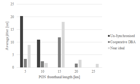
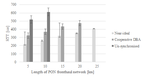
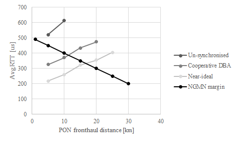
The figures show as expected the best results in the case of the near ideal fronthaul. The lower latency is due to the LTE traffic being prioritised. This scenario will require a high degree of coordination to align of the LTE and PON schedulers so that the upstream data arrives just as the PON frame is being packed. Also, if more LTE RUs/ONUs are associated with the same OLT, it might induce some delay anyway if more traffic has high priority.
VII Conclusion
The PON fronthaul is an economical way of using already established PON networks for fronthaul transmissions. This work demonstrates the use of XGS-PON for LTE fronthaul by first proving the feasibility of transmitting Cloud-RAN MAC/PHY split over XGS-PON, then it emulates a more realistic scenario where also background broadband traffic is included in the measurements.
This work considers a cooperative DBA solution for upstream transmission from RU to DU+CU where the latency is optimised in order to comply with mobile network latency requirements. The test-bed used for the measurements consisted of an OAI setup connected by a virtual XGS-PON network. The measurements showed satisfying results in terms of average RTT latency and average jitter. The initial feasibility studies without background traffic showed average RTTs below 150 us. From the results obtained including background traffic the maximum lenght of the XGS-PON fronthaul is unfeasible for the un-synchronised scenario, 11 km for the cooperative DBA scenario and 17 km for the near ideal scenario in order to stay below NGMN latency requirements.
This work proves the great potential for fronthaul transmission over PON and demonstrates how PON can be used to transport the MAC/PHY functional split. At the same time this work highlights the limitations in terms of latency when using PON as a fronthaul transport medium. We believe such number can be further increase with improvement in the synchronisation between DU and OLT, which will be carried out in future work.
Acknowledgement
Financial support from SFI grants 14/IA/252 (O’SHARE) and 13/RC/2077 and funding from BT and EPSRC iCASE award is gratefully acknowledged.
References
- [1] NGMN, “NGMN Overview on 5G RAN Functional Decomposition, Version 1.0,” White Paper, February, 2018.
- [2] C.-h. Lee, “Fiber to the Home Using a PON Infrastructure,” 2013.
- [3] H. Nomura, H. Ou, T. Shimada, T. Kobayashi, D. Hisano, H. Uzawa, J. Terada, and A. Otaka, “First demonstration of optical-mobile cooperation interface for mobile fronthaul with TDM-PON,” IEICE Communications Express, vol. 6, no. 6, pp. 375–380, 2017.
- [4] T. Tashiro, S. Kuwano, J. Terada, T. Kawamura, N. Tanaka, S. Shigematsu, and N. Yoshimoto, “A Novel DBA Scheme for TDM-PON based Mobile Fronthaul,” in Optical Fiber Communication Conference, (Washington, D.C.), p. Tu3F.3, OSA, 2014.
- [5] S. Zhou, X. Liu, F. Effenberger, and J. Chao, “Low-Latency High-Efficiency Mobile Fronthaul With TDM-PON (Mobile-PON),” Journal of Optical Communications and Networking, vol. 10, p. A20, jan 2018.
- [6] S. Das and M. Ruffini, “A Variable Rate Fronthaul Scheme for Cloud Radio Access Networks,” Journal of Lightwave Technology, vol. 37, pp. 3153–3165, jul 2019.
- [7] P. Alvarez, F. Slyne, C. Bluemm, J. M. Marquez-Barja, L. A. DaSilva, and M. Ruffini, “Experimental Demonstration of SDN-controlled Variable-rate Fronthaul for Converged LTE-over-PON,” in Optical Fiber Communication Conference, vol. 2018, (Washington, D.C.), p. Th2A.49, OSA, 2018.
- [8] G. Mountaser, M. L. Rosas, T. Mahmoodi, and M. Dohler, “On the Feasibility of MAC and PHY Split in Cloud RAN,” in 2017 IEEE Wireless Communications and Networking Conference (WCNC), pp. 1–6, IEEE, mar 2017.
- [9] G. Mountaser, M. Condoluci, T. Mahmoodi, M. Dohler, and I. Mings, “Cloud-RAN in Support of URLLC,” in 2017 IEEE Globecom Workshops (GC Wkshps), vol. 2018-, pp. 1–6, IEEE, dec 2017.
- [10] H. Ou, T. Kobayashi, T. Shimada, D. Hisano, J. Terada, and A. Otaka, “Passive optical network range applicable to cost-effective mobile fronthaul,” in 2016 IEEE International Conference on Communications (ICC), pp. 1–6, IEEE, may 2016.
- [11] L. M. P. Larsen, A. Checko, and H. L. Christiansen, “A Survey of the Functional Splits Proposed for 5G Mobile Crosshaul Networks,” IEEE Communications Surveys & Tutorials, vol. 21, no. 1, pp. 146–172, 2019.
- [12] NGMN, “Further Study on Critical C-RAN Technologies, Version 1.0,” White Paper, March, 2015.
- [13] NGMN, “5G RAN CU - DU network architecture, transport options and dimensioning, Version 1.0,” White Paper, April, 2019.
- [14] ITU-T, “G.987.3 (01/2014) 10-Gigabit-capable passive optical networks (XG-PON): Transmission convergence (TC) layer specification, 2020.
- [15] ITU-T, “G989.3 Amd 2. 40-Gigabit-capable passive optical networks (NG-PON2): Transmission convergence layer specification Amendment 2, 2018.
- [16] M. Ruffini, A. Ahmad, S. Zeb, N. Afraz, and F. Slyne, “The Virtual DBA: Virtualizing Passive Optical Networks to Enable Multi-Service Operation in True Multi-Tenant Environments,” Journal of Optical Communications and Networking, 2020.
- [17] N. Nikaein, M. K. Marina, S. Manickam, A. Dawson, R. Knopp, and C. Bonnet, “OpenAirInterface,” ACM SIGCOMM Computer Communication Review, 2014.