Color codes with twists: construction and universal gate set implementation
Abstract
Twists are defects in the lattice that can be used to perform encoded computations. Three basic types of twists can be introduced in color codes, namely, twists that permute color, charge of anyons and domino twists that permute the charge label of an anyon with a color label. In this paper, we study a subset these twists from coding theoretic viewpoint. Specifically, we discuss systematic construction of charge permuting and color permuting twists in color codes. We show that by braiding alone, Clifford gates can be realized in color codes with charge permuting twists. We also discuss implementing single qubit Clifford gates by Pauli frame update and CNOT gate by braiding holes around twists in color codes with color permuting twists. Finally, we also discuss implementing a non-Clifford gate by state injection, thus completing the realization of a universal gate set.
I Introduction
I.1 Motivation
Color codes are interesting from the point of view of fault tolerant quantum computation. In two dimensions they allow transversal implementation of Clifford gates Bombin and Martin-Delgado (2006). There are various ways of doing encoded computation using 2D color codes. One of the early approaches was due to Fowler Fowler (2011). In this information was encoded using holes and gates realized using code deformation. Independently, Landahl et al. Landahl et al. (2011) also proposed alternate protocols for fault tolerant quantum computation with color codes. They also used holes for encoding information, and code deformation for implementing encoded gates.
Lattice surgery Horsman et al. (2012); Landahl and Ryan-Anderson (2014); Litinski (2019) is an alternative to quantum computation with holes. Lattice surgery was used to show universal computation in color codes and the analysis of the resources required for the same was studied by Landahl and Ryan-Anderson Landahl and Ryan-Anderson (2014).
Twists are yet another method to encode information into a 2D lattice. Furthermore, they can also be used to perform encoded gates. Twists are defects in the lattice that permute the label of anyons. Loosely speaking, an anyon is the syndrome resulting from a violated stabilizer. Anyons in color codes have far richer structure compared to surface codes thus allowing for more permutations. Anyons in color codes are characterized by two labels, namely, charge and color. Twists in color code can permute charge, color or both. Kesselring et al. Kesselring et al. (2018) classified the various types of twists possible in color codes. However, certain aspects of color codes with twists were left unexplored. This motivates us to undertake a study of twists in color codes and their application to fault-tolerant quantum computation. Another reason for our study comes from the fact that twists can potentially lead to lower complexity for quantum computation. For instance, twists in surface codes are shown to provide gains in space time complexity of computation Hastings and Geller (2015).
Braiding in surface codes needs both lattice modification as well as stabilizer modification. A particular type of twist in color codes, viz. charge permuting twist, requires no lattice modification for movement. Only the stabilizers of the twist face and the faces in the path of the twist movement need to be changed. This can be accomplished without lattice modification for charge permuting twists. Therefore, braiding procedure is simpler in comparison to surface codes with twists.
I.2 Previous work and contributions
The use of dislocations for encoding was suggested by Kitaev Kitaev (2003). The ends of a dislocation are called twists. Twists in toric code model were first studied by Bombin Bombin (2010) where twists were shown to behave like non-Abelian anyons. Twists were studied from the perspective of unitary tensor categories by Kitaev and Kong Kitaev and Kong (2012). Yu and Wen You and Wen (2012) studied twists in qudit systems where the authors showed that twists exhibit projective non-Abelian statistics. Hastings and Geller Hastings and Geller (2015) showed that by using twists in surface code along with arbitrary state injection leads to reduction in amortized time overhead. Twists in surface codes were identified with corners of lattice by Brown et al. Brown et al. (2017) which helps in performing single qubit Clifford gates. Further, the authors also proposed a hybrid encoding scheme with holes and twists in surface codes that was made use of to implement CNOT gate. Surface codes with twists in odd prime dimension and braiding protocols to implement generalized Clifford gates were studied in Ref. Gowda and Sarvepalli (2020).
Twists have also been studied in other class of topological codes. Bombin Bombin (2011) studied twists in topological subsystem color codes and showed that Clifford gates can be implemented by braiding twists. Litinski and von Oppen Litinski and von Oppen (2018) studied twists in Majorana surface codes and have shown that all logical Clifford gates can be done with zero time overhead. Kesselring et al. Kesselring et al. (2018) have cataloged the twists in color codes. They have presented the basic twists with which all twists in color codes can be realized. We build upon their work, and explore in detail two types of twists in color codes namely, the charge permuting twists and color permuting twists. The work of Kesselring et al. Kesselring et al. (2018) approached color codes with twists from the abstract theory of boundaries and domain walls. In contrast, in this paper we take a more concrete approach giving explicit constructions and protocols for quantum computation. Our contributions are listed below.
-
(i)
We propose systematic constructions of color codes with charge permuting twists and color permuting twists from a -colex. We focus on type charge permuting twists. while Ref. Kesselring et al. (2018) focussed on type charge permuting twists. The color permuting twists we study have different lattice representation than the ones studied in Ref. Kesselring et al. (2018). This also results in a different string algebra for the Pauli operators.
-
(ii)
We propose an implementation of Clifford gates by braiding charge permuting twists. This result is stated in Theorem 16 for single qubit Clifford gates and in Theorem 17 for controlled- gate up to a phase gate on control and target qubits. Ref. Kesselring et al. (2018) did not provide explicit details of these protocols while they discussed code deformation using twists for implementing quantum gates.
-
(iii)
We propose an implementation of single qubit Clifford gates by Pauli frame update and CNOT gate by braiding holes around color permuting twists. The latter protocol is inspired by the work of Brown et al. Brown et al. (2017) who proposed using a combination of holes and twists for implementing CNOT gate in the context of surface codes.
Finally, we discuss the implementation of a non Clifford gate for both types of twists. The protocol is a minor variation of the one presented in Ref. Bravyi (2006) and could be of independent interest. A list of our main results is given in Table 1.
| Contribution / Twist type | Charge permuting twists | Color permuting twists |
|---|---|---|
| Code construction | Lemma 4 | Lemma 12 |
| Gates | Theorem 16 and Theorem 17 | Theorem 24 |
Our treatment of the color codes with twists makes extensive use of mappings between Pauli operators and strings on the code lattices. This approach brings out the geometry of the stabilizer generators and the logical operators in a very transparent fashion. Furthermore, it allows for a consistent and simplified analysis of the encoded gates using these codes.
I.3 Overview
In Section II, we briefly discuss color codes and review the work presented in Ref. Kesselring et al. (2018).
In Section III, we study charge permuting twists.
while Section IV is devoted to color permuting twists.
We discuss code parameters, logical operators and string representation for Pauli operators in the presence of color permuting twists.
In Section V, we show that encoded Clifford gates can be realized by braiding charge permuting twists.
In Section VI, we show that Clifford gates can be realized using charge permuting twists by Pauli frame update and joint parity measurements.
Notation. Some frequently used notation in the paper is given in Table 2.
| Notation | Meaning |
|---|---|
| , | Faces of color |
| Faces with colors or i.e., | |
| Vertices of a face | |
| Faces that share an edge with the face | |
| String of color encircling twists and |
II Background
We briefly review the necessary background on 2D color codes, see Bombin and Martin-Delgado (2006) for more details. Color codes are defined on trivalent and three-face-colorable lattices embedded on a two dimensional surface. Such lattices are called -colexes. A well known example of trivalent and three colorable lattice is the honeycomb lattice. Two stabilizers generators are defined on every face of the lattice:
| (1) |
where denotes the vertices that belong to the face and and are the Pauli operators. The stabilizers defined in Equation (1) apply to faces of all colors. However, not all stabilizers are independent. They satisfy the following relations Bombin and Martin-Delgado (2006),
| (2a) | |||||
| (2b) | |||||
Here denotes the set of faces of color . Equations (2) indicate that there are four dependent stabilizers. The number of logical qubits depends on the topology of surface on which graph is embedded. If the surface has genus , then the number of encoded qubits is . The genus of a surface is half the number of independent non-contractible loops that can be drawn on the surface. For instance, any loop drawn on a sphere can be contracted to a point and hence its genus is zero. On a torus, one can draw two independent non-contractible loops and hence its genus is .
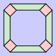
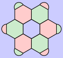
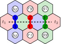
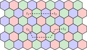
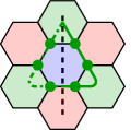
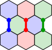
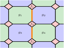
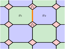
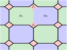
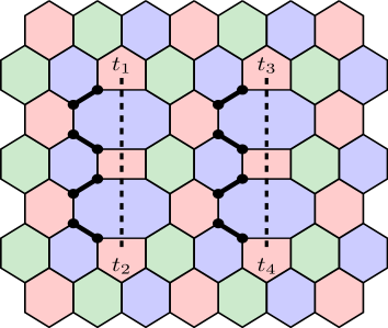
Of particular interest to us in this paper is the case . Examples of such lattices are shown in Fig. 1. Two stabilizers, type and type, are defined for each face of the lattice. All vertices in the lattice are trivalent and hence we have , where and are the number of edges and vertices of the lattice respectively. Using this in the Euler characteristic equation , where is the number of faces, we get . It is easy to verify that this lattice also obeys the constraints given in Equations (2). Therefore, the number of independent stabilizers is , thus giving zero encoded qubits.
II.1 Previous work on twists in color codes
We now review some relevant material from Ref. Kesselring et al. (2018). The syndromes in color codes can be written as where denotes the color of face on which the syndrome is present and denotes the type of stabilizer violated. If a error occurs, then both and stabilizers are violated which is indicated as . The syndromes present in the color code are given in Table 3 Kesselring et al. (2018).
Twists are defects in the lattice that permute a label of an anyon to another i.e. they permute anyons when anyons go around twist (more precisely, when they cross the domain wall). Domain wall is a virtual path in the lattice that marks the point where anyons are permuted. In color codes with twists, there is more than one way to permute anyons and the corresponding twists are given below.
-
a)
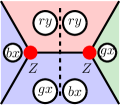
Charge permuting twists. These twists exchange the Pauli label of a pair of anyons in a column of Table 3 while leaving the third unchanged. For example, and labels are exchanged and label is left unchanged. These twists do not permute the color. For example, is permuted to and vice versa but is unaltered.
-
b)
Color permuting twists. These twists correspond to exchange of the color label of a pair of anyons in a row of Table 3. They leave the color of the third entry in that row unchanged while exchanging the colors of the other two entries. Note that these twists permute only color but not charge. For example a twist that leaves red anyons unchanged but permute to and vice versa. This corresponds to exchanging the corresponding entries in two rows in Table 3.
-
c)
Domino twists. Apart from exchanging anyons along rows and columns, one can also exchange them across the diagonal in Table 3. In this case, the twist acts by transposition i.e. the diagonal entries , and are unaltered whereas the following permutations take place: , and . This transformation can also be seen as permutation of color and charge labels: , and . The anyons , and contain the charges that are mutually permuted and hence are left invariant whereas the other bosons are permuted. For example, under this permutation will be permuted to which is the diagonally opposite entry in Table 3.
Remark 1.
It is to be noted that these are fundamental twist types. One can combine two or more of these twist types to obtain other twists.
| Features / Twist type | Charge permuting | Color permuting | Domino |
|---|---|---|---|
| Lattice modification | Not needed | Needed | Needed |
| Physical qubits added or removed from lattice | No | Removed | Added |
| Type of code | non-CSS | non-CSS† | non-CSS |
| Geometry of logical operators | Closed strings encircling a pair of twists | Closed strings encircling a pair of twists | Closed strings encircling a pair of twists |
| -line | Absent | Present | Absent |
by choosing or type stabilizer on twist face.
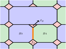
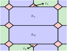
A comparison of various twist types is given in Table 4. For completeness we have also included all the three fundamental types of twists in color codes. For the rest of the paper we only consider charge and color permuting twists. In the following sections we assume that the lattices are obtained by embedding graphs on a two dimensional plane. We also assume that the boundary of lattices have the same color as given in Fig. 1(a) and Fig. 1(b).
II.2 Pauli operators as strings in color codes without twists
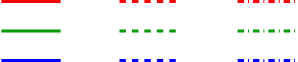
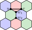
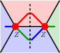
In this section, we give a mapping between Pauli operators and strings on color code lattices without twists. This correspondence is useful in abstracting away the lattice information and studying the code properties using the string algebra. The three single qubit Pauli operators, namely, , and are represented using three different types of strings. A solid string of any color represents Pauli operator , a dashed string of any color represents Pauli operator and a dash-dotted string of any color represents Pauli operator , see Fig. 2.
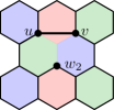
We begin by representing a Pauli operator on a vertex in a color code without twists. When a Pauli error occurs on a vertex, syndromes are created on all the three faces incident on that vertex, see Fig. 3(a). This is because, all the faces have both and type stabilizers defined on them and an error violated at least one of these stabilizers. A single Pauli is represented by a string with three terminals as shown in Fig. 3(b). The end point of the strings are interpreted as syndromes. Now consider applying the same error operator on two adjacent vertices as shown in Fig. 3(c). This can be understood from stabilizer viewpoint. The error operator commutes with the stabilizer of the blue face and hence no syndrome should be observed on this face. Similarly, on the green face, the syndromes vanish. (In effect two syndromes fuse to vacuum.) The string representation of Fig. 3(c) is shown in Fig. 3(e). This representation is obtained from the single qubit representation shown in Fig. 3(b). The two stings on blue and green faces are connected as these faces do not host syndromes. On the other hand, on the red faces the string is terminated indicating the presence of syndromes.
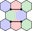
Note that if one of the red faces hosts a syndrome , then applying the operator shown in Fig. 3(d) annihilates the syndrome on the face with prior syndrome and creates one on other without any prior syndrome. This process can be seen as moving the syndrome between adjacent faces of the same color. The operators that move syndromes are known as hopping operators Bhagoji and Sarvepalli (2015). A compact representation of the string in Fig. 3(e) is given in Fig. 3(f). Note that the string is drawn dashed indicating that is represents Pauli operator and its color is red indicating that red edges are in its support.

III Charge permuting twists
In this section, we discuss charge permuting twists. The process of twist creation and movement corresponds to code deformation Bombin and Martin-Delgado (2009). After reviewing the procedure to create charge permuting twists, we derive the number of encoded logical qubits by stabilizer counting. We also give logical operators for the encoded qubits. We give a mapping between Pauli operators and strings on the lattice.
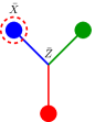
Charge permuting twists are faces in the lattice that permute the Pauli labels of anyons that encircle them. A type charge permuting twist acts as follows:
| (3a) | |||||
| (3b) | |||||
| (3c) | |||||
where , and are distinct Pauli labels. An example is the twist Kesselring et al. (2018) that exchanges the and labels of anyons while leaving the label unchanged. The twist leaves the label unchanged and exchanges the and labels, see Fig. 4(a), and the twist exchanges and labels leaving the label unchanged. Lattice modification is not required for creating charge permuting twists but only stabilizers of certain faces need to be modified Kesselring et al. (2018).
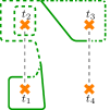
Before moving on to twist creation, we need a notion of how far apart the twists are as the code distance depends on it.
The dual of a lattice is constructed by mapping the faces in to vertices, and connecting two such vertices if the faces in the primal lattice share an edge. This construction maps faces to vertices, edges to edges and vertices to faces in the dual lattice. Now we can precisely state how far apart two charge permuting twists are.
Definition 2 (Twist separation).
Separation between twists is the distance between the vertices corresponding to twists in the dual lattice.
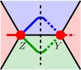
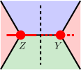
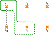
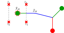
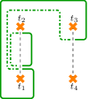
As an example, consider the separation between twists in Fig. 4(b) where the separation between twists , and , is three and four respectively. The domain wall in Fig. 4(b) between and has been drawn to illustrate that a domain wall need not be the shortest path between twist faces. The twist separation in that case still conforms to the above definition. Twist separation determines the code distance, for this reason we include this as a design parameter while constructing color codes with twists.
III.1 Creation of charge permuting twists
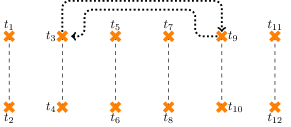
We now summarize the procedure to create pairs of charge permuting twists in a -colex. In case of charge permuting twists, there are no physical dislocations in the lattice. Twists are introduced by breaking the uniformity of stabilizer assignment for each face of the 2-colex. To introduce pairs of charge permuting twists, we first need to choose vertices in the dual lattice such that any pair of them are at least a distance apart. Now, connect a disjoint pair of vertices by a path so that no two paths crossover. The faces corresponding to the terminal points of a path become the twists while the path connecting them becomes a domain wall. The faces which correspond to the intermediate vertices of the path are the ones through which the domain wall passes through, see Fig. 4(b). Once the twists and the faces through which domain wall passes through are chosen, assign the stabilizers on them as discussed next.
Faces in color code lattices with charge permuting twists can be grouped into three categories: i) twists, ii) faces through which domain wall passes through and iii) faces that are neither twists nor faces through which domain wall passes through. Stabilizers for the twist are given in Ref. Kesselring et al. (2018). We give the stabilizer assignment for the twist.
Two stabilizers are defined on faces that are neither twists nor through which domain wall passes through:
| (4) |
The faces through which domain wall passes through has to permute the labels and of anyons while leaving the label unchanged. This will happen if the Pauli operators of stabilizers on one side of the domain wall are of type ( type) and on the other side they are of type ( type). Let the domain wall partition the vertices of a face into two sets and . Two stabilizers are assigned to such faces as defined below:
| (5a) | |||||
| (5b) | |||||
The stabilizers defined in Equations (5) are shown in Fig. 5. The stabilizer assigned to the twist face has to commute with the stabilizer defined on the face adjacent to it through which domain wall passes through. These two faces share exactly one edge. Given the assignment in Eq. (5) and (4), the only possible stabilizer that can be assigned to the twist face is that of type,
| (6) |
Stabilizer dependency. The stabilizer assignment in Eq. (4)–(6) is constrained by the following relations:
| (7a) | |||||
| (7b) | |||||
where , and denote the set of twist faces, modified faces and unmodified faces respectively. From Equations (7), we can see that one of the green and blue face stabilizers is dependent. We take the outer unbounded blue face stabilizer to be the dependent one. Since two stabilizers are defined on the unbounded blue face and only one of them is dependent, we have to measure the other non-local stabilizer which is undesirable. We therefore discard one of the stabilizers and redefine the unbounded blue face stabilizer as
| (8) |
This stabilizer still satisfies the constraint in Equations (7).
Stabilizer commutation. Note that any two adjacent faces share two common vertices. The Pauli operators corresponding to stabilizers are either same or different on the common vertices. Hence, stabilizer commutation follows. A more detailed analysis is given in Appendix A.
Remark 3.
The stabilizers of color code with twist can be obtained from that of the twist by applying phase gate on all qubits.
We summarize with the following result on the parameters of color codes with charge permuting twists.
Lemma 4 (Encoded qubits for charge permuting twists).
A color code lattice with charge permuting twists encodes logical qubits.
Proof.
In a color code lattice with charge permuting twists, all vertices are trivalent. Therefore, we have , where and are the number of edges and vertices of the lattice respectively. Using this in the Euler’s formula, , where is the number of faces, we get, . Only one stabilizer is defined on twist faces and the unbounded face while the remaining faces we define two stabilizer generators. Therefore, the number of stabilizers is . Accounting for the dependencies (see Equations (7)), we obtain, independent stabilizer generators. Since total number of qubits is , the number of encoded qubits is . ∎
III.2 Pauli operators as strings on a color code lattice with charge permuting twists
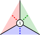
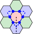
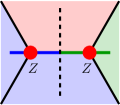
The representation of the Pauli operators by strings as given in Fig. 3 does not work in the presence of charge permuting twists as these twists permute the charge label of anyons. Consider the operator shown in Fig. 6(a). The upper blue face is twist, domain wall passes through the green face and red faces are neither twists nor faces through which domain wall passes through. Red faces are normal faces. The Pauli operator creates two syndromes on twist face and syndromes and on the green face. Also, and syndromes are created on red faces. Syndromes on the twist face annihilate each other and hence the string is continuous in twist face.
However, the Pauli operator commute with the stabilizers of the green face. Therefore, string is continuous in green face too, see Fig. 6(b). The red faces host anyons and hence the string terminates there. An alternate representation for the operator described in Fig. 6(a) is given in Fig. 6(c). Note that in Fig. 6(c), the string changes midway as it crosses the domain wall.
String representation of stabilizers. We represent the stabilizers using the string representation just developed. Twist stabilizer in string notation is given in Fig. 6(d). Note that the twist is assigned type stabilizer and hence the string is dashed. Also, the twist does not permute label and hence the string is not changed as it crosses the domain wall. An alternate representation of twist stabilizer in Fig. 6(d) would be to take green string instead of blue. Stabilizers of faces through which domain wall passes through is given in Fig. 6(e) and Fig. 6(f). These stabilizers are of mixed type with () on vertices on one side of the domain wall and () on vertices on the other side of domain wall. Note that the strings change as they cross domain wall. For other faces that are not twists and through which domain wall does not pass through, the strings are of type and type.
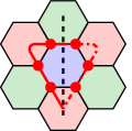
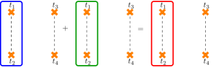
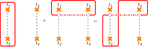
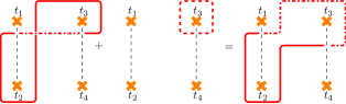
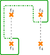
String representation of logical operators. Logical operators (including stabilizers) are closed strings encircling an even number of twists. A closed string enclosing exactly a pair of twists is a nontrivial logical operator. Further, we also need to show that these operators are not generated by stabilizers. This is done by showing the existence of a string whose operator anticommutes with that of the given string, see Fig. 7(a) and Fig. 7(b). These operators are logical and operators respectively. An important property of a logical operator is that it commutes with all the stabilizers. Every closed string must enter and exit a face an even number of times. Therefore, every face shares an even number of common vertices with the logical operator. This also holds for faces through which domain wall passes through. Taking into account the stabilizer structure of domain wall faces, we conclude that the operators shown in Fig. 7 commute with all stabilizer generators.
Note that the product of twist stabilizers , and the stabilizers defined on faces through which domain wall passes through (except the blue face) has the same support as the operator shown in Fig. 7(b) with on vertices in the support. The product of these stabilizers with the logical operator in Fig. 7(b) flips the Pauli operator on all vertices in its support to . Therefore, the two operators are equivalent up to stabilizers. The same holds true for logical operator shown in Fig. 7(a). Pauli operators and can be flipped by taking the product of twist stabilizers on and and the blue face on which the operator has support.
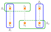
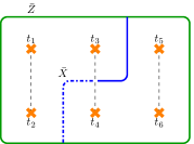
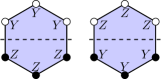
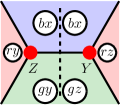
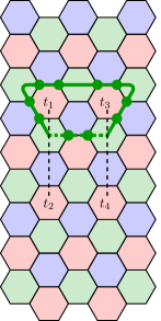
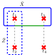
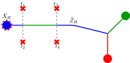
For purposes of simple representation of twist and logical operators, we hide the lattice information and represent only twists, domain walls and logical operators. Logical operators are represented as closed strings. These strings are edges in a modified lattice of the color code. These modified lattices are called shrunk lattices. A shrunk lattice of color is obtained by shrinking all faces of color in the lattice to vertices. Equivalently, we can contract the edges of the lattice that are not colored . Observe that upon crossing the domain wall, color of the string is unaffected. Logical operators when three pairs of twists are present in the lattice is given in Fig. 8(a).
The disadvantage with this choice of logical operators is that whenever a gate is to be performed only on a particular encoded qubit by braiding, say encoded qubit (), we also end up performing a gate on logical qubit () (see Fig. 8(a)) which is undesirable. Therefore, we treat encoded qubits and as gauge qubits. The encoded qubits that do not carry any useful information are called gauge qubits.
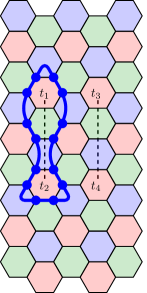
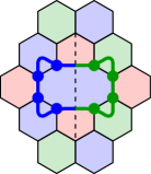
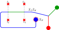
The canonical form of logical operators for encoding is shown in Fig. 8(b). With encoding, a closed string encircling three pairs of twists encoding two logical qubits is a stabilizer. We use encoding which encodes two qubits per six twists for implementing gates by braiding.
Theorem 5.
A color code with charge permuting twists with encoding defines an subsystem code with gauge qubits.
Remark 6.
Code distance. Distance of the code is the minimum weight of the operator in where is the stabilizer and is the centralizer of stabilizer. The centralizer of a subgroup of a group is the set of all elements of that commute with every element of the group. It is denoted as denoted as and formally defined as
The centralizer and normalizer are same for subgroups of the Pauli group. A logical operator corresponds to a nontrivial closed string that encircles an even number of twists. As in the case of surface codes with twists, the shortest of the nontrivial strings are those that encircle a pair of twists. These strings have weight , where is the separation between twists. Therefore, we conjecture that the distance of the code is .
We use the charge permuting twists constructed in this section for realizing encoded Clifford gates by braiding. These results are presented in Section V.
IV Color permuting twists
In this section, we present the construction of color permuting twists. Our construction differs from the one given in Ref. Kesselring et al. (2018) and is more along the lines of Ref. Bombin (2011). We first address the modification of an arbitrary -colex to create color permuting twists. While creating twists, we should also ensure that the code resulting from lattice modification has the specified distance. This is accomplished by tailoring the separation between twists. We then discuss stabilizer assignment, code parameters and logical operators.
Color permuting twists are faces in the lattice which permute the color label of anyons that encircle them. A -type color permuting twist acts as follows:
| (9a) | |||||
| (9b) | |||||
| (9c) | |||||
where the colors , and are all distinct. Observe that color permuting twists fix one color and exchange the other two. The Pauli label of an anyon is not altered by color permuting twists.
IV.1 Creation and movement
Intuition. In a -colex, edges of a specific color connect the faces of the same color, see Fig. 10(a). As a result, the syndromes can only be moved between faces of same color. In order to create color permuting twist, we need to introduce an edge between two faces of different color. Suppose that we introduce an edge between blue and green face, see Fig. 10(b). This edge cuts through the common red face to the blue and green faces. This move also makes the vertices and tetravalent and splits the red face into two: the upper pentagon face and the lower triangular face. It is not possible to assign stabilizers to the new red faces such that they commute with the rest Anderson (2013). Therefore, the vertices and have to be made trivalent. This is done by removing the common neighbor to vertices and , see Fig 10(c). The vertex is rendered two-valent by this move. The neighbors of the vertex are connected by an edge making them tetravalent. The tetravalency of the neighbors of is resolved by removing the vertex , see Fig 10(d). Note that the new edge also connects blue and green faces. The face in between twists has mixed color. One can assign either blue or green color to this face. Similar procedure is followed for moving twists apart. The twist created in this illustration is red twist since it permutes green and blue labels leaving the red label unchanged. Other twists like green twist and blue twist are defined similarly.
Remark 7.
Note that the twist faces have an odd number of edges. This breaks the three-face-colorability in the vicinity of such faces of the lattice and creates color permuting twists.
We would like to introduce pairs of twists of the same color in a -colex. To do so, we first choose an even number of vertices of the same color in the dual lattice such that any pair of them is at least a distance apart. A path is introduced between disjoint pairs of vertices so that no two paths overlap. The challenge faced in constructing color permuting twist is mainly the selection of faces in such a way that the intermediate faces between twists do not grow unbounded. The aforesaid path is not arbitrary but has to satisfy the properties given below.
-
C1)
The faces corresponding to the nearest -colored vertices on the path are connected by an edge in the original lattice.
-
C2)
Let , and are three consecutive -colored vertices on the path and such that distance between and is two and distance between and is two in the dual lattice. The vertex cannot be at a distance of two from .
The first condition ensures that the faces with color and are merged during twist creation. The second condition ensures that the intermediate faces between twists do not grow in size. With this, one can create an even number of twists in an arbitrary -colex. Note that we do not use edge coloring in our work. The procedure to create color permuting twists in an arbitrary -colex is given in Algorithm 7.
Algorithm to create pairs of -color permuting twists in a -colex.
Input: -colex, separation between twists .
Output: Trivalent lattice with pairs of color permuting twists.
Remark 8.
If a third -colored vertex from a given vertex is at is at a distance two, then multiple edges are introduced during the execution of Algorithm 7. If multiple edges are introduced, then remove the vertices incident on multiple edges and connect the resulting two-valent vertices.
Remark 9.
The process of twist creation can also be understood as deleting the orange edge in Fig. 11(c) and then contracting one edge in each divalent vertex.
IV.2 Stabilizers
We need not modify a majority of stabilizers for color codes with color permuting twists. Every face which is not a twist has an even number of edges. Hence, two stabilizers are defined on such faces:
| (10) |
However, on a twist face , we cannot define two stabilizers as they will anti-commute.
A -type stabilizer is defined on the twist face Kesselring et al. (2018):
| (11) |
Consistency of stabilizer assignment. If two faces are adjacent, then they share two common vertices. To check commutation between adjacent face stabilizers, we have to check commutation on these vertices. The stabilizers are all either type or type. If the Pauli operator on the common vertices is same, commutation follows. On the other hand, if the Pauli operators on the common vertices are different (for instance, or on one of the faces and on the other face), then there are two anticommutations and the stabilizers commute. Therefore, all stabilizers commute.
Stabilizer dependencies. Giving stabilizer dependencies for the general case is difficult. We restrict to lattices where all twist faces are red. Then the stabilizer generators have to satisfy the following constraints:
| (12a) | |||||
| (12b) | |||||
where the product over blue faces includes blue modified faces and the outer unbounded blue face. These constraints indicate the presence of two dependent stabilizers. We take the dependent stabilizers to be the ones defined on the unbounded blue face.
Proposition 10.
Algorithm 7 creates color permuting twists.
Proof.
To prove that Algorithm 7 creates color permuting twists in conjunction with the stabilizer assignment in Eqs. (10) and (11), it suffices to show that the algorithm introduces an edge between faces of different color while preserving trivalency of vertices. When an anyon is moved along this edge, its color is permuted. Let and be the vertices marked for deletion in the algorithm. Let and . Note that and do not exist before twist creation. Due to the property of -colex that the set of faces sharing an edge with any given face can be colored with two colors, the edges and connect faces of different color. Algorithm 7 removes vertices and and introduces edges and thereby creating an edge between faces of different color. Stabilizers on the unmodified faces are not changed. Also, the stabilizer on the twist face is of type. Therefore, any operator , where will commute with the twist stabilizer while moving the syndrome from face of one color to another. Apart from these, the modified face in between twist has edges of different colors incident on it. As a result, whenever an anyon enters and exits this faces through edges of different color, it color label is permuted. Stabilizers defined on modified faces are of and type. Therefore, the error operators that move the syndrome across modified faces commute with the stabilizers defined on them. ∎
Lemma 11 (Parity of color permuting twists).
Color permuting twists are created in pairs.
Proof.
Let be the lattice with color permuting twists and let be its dual. Note that color permuting twists are odd cycles and hence vertices corresponding to them have odd degree in the dual lattice. Since the number of vertices with odd degree should be even in a graph Diestel (2017) (and hence its embedding on a surface), color permuting twists are created in pairs. ∎
-lines and domain walls. When color permuting twists are created in the lattice, local three colorability around twist faces is destroyed. As a consequence, we can find a sequence of edges, having the same color as the twist face, along which faces of the same color meet. On the (red) shrunk lattice these edges form a path terminating on the vertices corresponding to the twist faces. We refer to this sequence of edges as a -line following Bombin (2011). For instance, if the twist face is red, then this path is formed by red edges and along this path blue and/or green adjacent faces meet. An example of trivalent lattice with twists along with -line is shown in Fig. 12. Existence of -lines in the presence of color permuting twists is proved in Appendix C. Note that for this specific coloring of the lattice domain walls run parallel to the -line. A different coloring might be possible where the -line crosses the domain wall as for instance happens in case of surface codes with twists Gowda and Sarvepalli (2020).
Coding theoretic view of color permuting twist creation. The process of color permuting twist creation can be understood in terms of classical code puncturing Huffman and Pless (2003). In classical codes, code puncturing is done by deleting one or more (classical) bits and readjusting the parity check and generator matrices if necessary. While creating twists in color codes, two qubits are removed from the system, see Fig. 11(c). Suppose that stabilizers are written in symplectic form. Let and be the top and bottom red faces in the figure and let and be the green and blue faces respectively. Due to qubit removal, one qubit is removed from the stabilizers on . This leads to anti commutation among the stabilizers on . The anti commutation is rectified by dropping a stabilizer (either or type). The same holds true for stabilizers on . Now, the stabilizers on and anti commute with stabilizer on . The resolution of this anticommutation comes from merging the corresponding and stabilizers on and . In this process, we have deleted two columns, one row each of stabilizers of and and merged the rows of and . This process is exactly similar to code puncturing in classical codes. Therefore, color permuting twist creation is the analogue of code puncturing in quantum codes.
For a general 2-colex into which color permuting twists are introduced the following result holds.
Lemma 12 (Encoded qubits for color permuting twists).
A 2-colex with color permuting twists encodes qubits where is even.
Proof.
Note that in lattice containing color permuting twists, all vertices are trivalent. Hence, we have , where and are the number of edges and vertices (qubits) of the lattice respectively. Also, , where is the number of faces in the lattice. Therefore, we get, . We count two stabilizers for every face, including twists. Subtracting the dependent stabilizers, which are in number gives the number of remaining stabilizers to be . Ignoring the outer unbounded face stabilizers (see Equations (12)), we obtain the independent stabilizer generators to be . Hence, the number of encoded qubits is . ∎
Remark 13.
The number of encoded qubits here is twice that of surface codes with twists Gowda and Sarvepalli (2020). The reason is, with the introduction of a twist pair in surface codes, one stabilizer was removed and hence one new encoded qubit. However, in color codes with every twist pair, two stabilizers are removed and hence we get twice the number of encoded qubits.
IV.3 Pauli operators as strings on a 2-colex with color permuting twists
In this subsection, we give a string representation of Pauli operators on a 2-colex in the presence of color permuting twists. Consider Fig. 13(a) where Pauli operator is applied on the vertices of the edge. The red face on the top is twist, green and blue faces on the right and left of twist are unmodified faces and the bottom face with blue color is the modified face. The Pauli operators create two syndromes on the twist face, and on the normal blue and green faces respectively and , on the modified face (the part of the modified face to the right of the domain wall supports anyons with green color label). Anyons on the twist face annihilate each other and hence the string is continuous in the twist face. The Pauli operator commutes with the stabilizers on the modified face and therefore string is continuous in modified face too, see Fig. 13(b). String representation of the Pauli operator in Fig. 13(a) is given in Fig. 13(c). Note that the string changes color as it crosses the domain wall.
Stabilizers on modified faces cannot be represented as strings with one color, see Fig 13(d) and Fig. 13(e). For the same string, both and stabilizers are defined. Note the strings change color as they crosses the domain wall.
As in the case with charge permuting twists, logical operators are closed strings encircling an even number () of twists. (A string encircling an odd number of twists will be an open string.) The above mentioned logical operators are not generated by stabilizers. The reason being one can find another string encircling a pair of twists that anticommutes with the given string, see Fig. 14(a) and Fig. 14(b). The logical operators for one of the encoded qubits is shown in Fig. 14. Logical operator is the string which encircles twists not created together, see Fig. 14(a). Logical operator is the string that encircles twists created together, see Fig. 14(b). Note that with every pair of twists introduced, the number of encoded qubits increases by two.
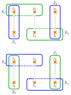
Henceforth, we consider all twists to be of the same color. The reason for this is that when twist pairs are of different color, logical operator has the form shown in Fig. 15(a). To avoid such self-intersecting logical operators, we choose all twists to be of the same color. Logical operators for encoded qubits in color codes with color permuting twists is given in Fig. 15(b). The string encircling twists and is the logical operator and the one enclosing twists and is the logical operator. When two strings of same color intersect they overlap in even number of locations, therefore they commute. Only when strings of different color intersect they overlap in one location, therefore they anticommute. From this we conclude that the operators in Fig. 15(b) anticommute. Even when the support of both logical operators intersect where the colors are same, the size of the common support is always an even number. We choose to use encoding for the same reason as that for charge permuting twists. The canonical form of logical operators for encoding is shown in Fig. 15(c).
Remark 14.
With encoding, we get gauge qubits.
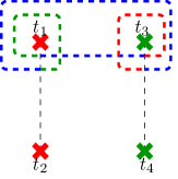
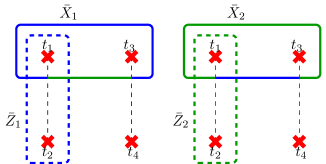
V Clifford gates using charge permuting twists
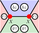
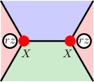
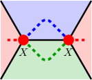
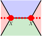
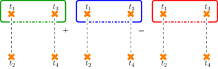
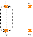
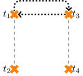
In this section, we show that encoded Clifford gates can be realized with charge permuting twists by braiding alone. We use encoding while realizing gates, see Fig 8(b). Braiding twists and induces a permutation . This naturally leads to a transformation of closed strings enclosing the twists. Denote a string of color enclosing twists and by . After braiding twists and , the string encircling them is unchanged. However, a string encircling twists and other twist after braiding (of and ) is mapped to . In other words, after braiding . Let , and be twists as shown in Fig. 16. The list of logical operators and corresponding strings is given in Table 5. In some case a logical operator has an equivalent representation obtained by adding a gauge operator, see Fig. 9. However, strings corresponding to logical operator do not have equivalent strings of different color of the form .
| String | Equivalent string | Logical Operator |
|---|---|---|
Remark 15.
The string corresponding to is not equivalent to , unlike and . It turns out that and correspond to operators and respectively.
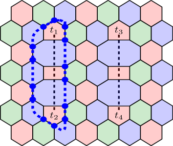
Theorem 16 (Single qubit Clifford gate).
Let , and be twists that encode a logical qubit and let , and be the strings corresponding to logical operators , and respectively. Then,
-
i)
Braiding and realizes phase gate ( rotation by ).
-
ii)
Braiding and realizes rotation by .
Proof.
The encoding used is as shown in Fig. 8(b). The logical operator (up to gauge operators) is shown in Fig. 22(b). After braiding twists and we have, , and . Using this we get the transformation given below.
The string is unchanged since the twists encircled by it are braided. Transformation of is shown in Appendix B and transformation of to is straightforward. Similarly, braiding and , we get the following transformation.
Hence, the theorem follows. ∎
Hadamard gate can be realized by rotation and phase gates. Hence and rotations by suffice to realize single qubit Clifford gates by braiding.
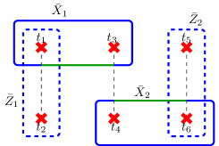
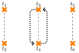
To complete the Clifford group, we need an entangling gate. We prove below that braiding the twist pair shared by two logical qubits accomplishes this. Let , and be twists that encode the logical qubit and let , and be twists that encode the logical qubit in the same block as shown in Fig. 17(a). The operator corresponding to string encircling twists and is the product of operators encircling twists , and , i.e. . This can be seen easily as the logical operators in the form of closed strings can be opened up and running between boundaries. This is possible as the logical operators encircling twists created in pairs have support on blue strings which can be deformed to end on the unbounded blue face. Then, by adding stabilizers, the open strings can be made to encircle twists and . Similarly, for qubits not in the same block, see Fig. 17(c), the string encircling twists , and , can be deformed in similar way to that in surface codes Gowda and Sarvepalli (2020). The twists encoding qubits is given in Table 6.
| Encoded qubit | Twists used |
|---|---|
| , , | |
| , , | |
| , , | |
| , , |
Theorem 17 (Entangling gate).
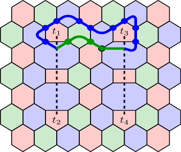
Controlled-Z gate is realized up to phase gate on control qubit and target qubit by the following braiding.
-
i)
Braid and for qubits in the same block.
-
ii)
Braid and for qubits in different block.
Proof.
We prove for the qubits in the same block. Extension to qubits from nonadjacent block is straightforward. Encoding used is as shown in Fig. 8(b). After braiding and , we have , , . We have the following transformation.
In the third and the last transformations, the deformed strings can be expressed as and respectively, see Fig. 22 in Appendix B. This transformation is similar to that of combining and to give . By noting the logical operator transformation on the right side, we can conclude that braiding twists and results in controlled- gate up to a phase gate on control and target qubits. ∎
After performing the braiding as indicated in Theorem 17, performing phase gate on control and target qubits will realize controlled- gate between them. Phase gate is performed by braiding the twist pair encircled by the logical operator. The procedure to realize the entangling gate stated in Theorem 17 between the other encoded qubit pairs is given in Table 7.
| Encoded qubits | Braid to be performed |
|---|---|
Theorem 18.
In a color code with charge permuting twists, Clifford gates can be realized by braiding alone.
We now summarize the braiding protocols for realizing Clifford gates in Table 8.
VI Clifford Gates using color permuting twists
In this section, we describe the implementation of Clifford gates using color permuting twists. We use four color permuting twists to encode a logical qubit, see Fig. 18(a).
For realizing phase and Hadamard gates, we use Pauli frame update Hastings and Geller (2015). Pauli frame update is done classically. In this procedure, one has to keep track of the Pauli frame for each encoded qubit i.e. one has to maintain the information whether the canonical logical operator labels are exchanged. Phase gate is realized by interchanging the labels of and logical operators and for realizing Hadamard gate, the labels of and logical operators are interchanged. If a measurement is to be done after Hadamard gate, then after Pauli frame update, we take into account the Pauli frame update and measure the canonical logical operator.
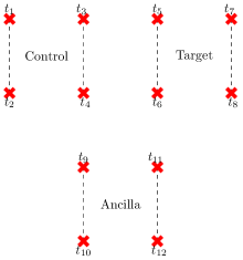
We implement CNOT gate by making use of an additional ancilla qubit and holes Terhal (2015); Brown et al. (2017). This is done by joint parity measurement and joint parity measurement with an ancilla qubit. The protocol is given in Table 9.
| Protocol for implementing CNOT gate Terhal (2015) | |
| (1) | Prepare ancilla in the state . |
| (2) | Perform joint parity measurement on ancilla and target qubit. |
| (3) | Perform joint parity measurement on ancilla and control qubit. |
| (4) | Perform Hadamard on ancilla qubit and measure it in basis. |
| (5) | Measure ancillas and apply correction as given in Equation 16. |
Suppose that and are the states of control and target qubits with and . Let the measurement outcome of joint parity measurement be and those of joint parity measurement and ancilla measurement be and respectively. Then it can be shown that at the end of the protocol the initial state is modified as Terhal (2015)
| (16) |
Ancilla qubit is disentangled by measuring in the basis.
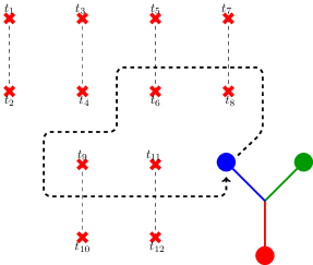
Motivation for using holes. The encoded CNOT gate protocol given in Table 9 involves joint parity measurement of logical and logical operators. These operators are high weight owing to the separation between the twists. (We keep the twist separation large to make the distance large.) Therefore, measuring the the joint operators by doing gates between physical qubits in the support of logical operators and ancilla qubit fault-tolerant will be quite complex. However, an alternate scheme exists for doing fault-tolerant measurement of these operators. This alternate scheme in the context of surface codes involves creating holes, braiding them around twists and measuring them Brown et al. (2017). We adapt this technique to the color permuting twists.
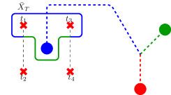
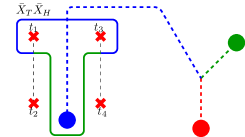
Holes in color code lattices. Here we briefly review holes in color code lattices. For a more detailed treatment of holes in color codes, we refer the reader to Ref. Fowler (2011). A hole is a region in the lattice where stabilizers are not measured. Suppose that we have to introduce a red hole in the lattice. We choose a red face and do not measure the stabilizers defined on it. To expand the hole, we take the vertices on one of the edges incident on the face. Then and measurements are performed on the qubits on the vertices of the chosen edge. Using this procedure, a hole can be made arbitrarily big. We use triple hole encoding Fowler (2011). Two more twists, one each of green and blue colors, are created by the same procedure. A logical qubit encoded in a hole is shown in Fig. 18(b) and Fig. 18(c). Logical operators are the strings encircling hole and the string net (in the shape of T). Depending on whether we choose or logical operator to encircle the hole, we get primal and dual qubits respectively. The encoding shown in Fig. 18(b) is that of a primal qubit whereas the encoding in Fig. 18(c) is that of a dual qubit.
VI.1 Hole-twist braiding
We now show how logical operators are modified by braiding a hole around twists. Three hole encoding Fowler (2011) is used, see Fig. 18(b) and Fig. 18(c). In this scheme, a logical qubit is encoded using three holes (of different color). For primal qubit, the logical operator is the string encircling a hole and the logical operator is the string having tree like structure connecting the three holes. For the dual qubit, the logical operator is the string encircling the hole and logical operator is the string having tree like structure. The idea of braiding holes around twists to implement CNOT gate was proposed in Ref. Brown et al. (2017) in the context of surface codes. In this paper, we explore the same idea in the context of color permuting twists.
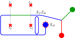
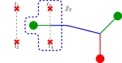
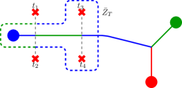
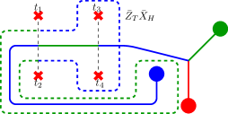
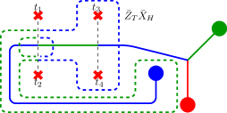
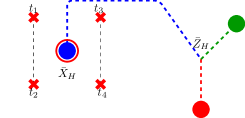
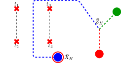
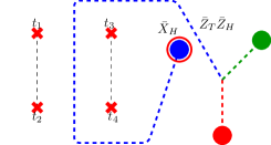
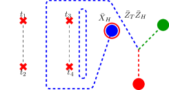
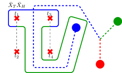
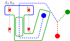
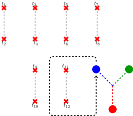
Consider the braiding as shown in Fig 19. Let and be the and logical operators of logical qubit encoded by twists and let and be the and logical operators of logical qubit encoded by holes. The hole is braided around twists and . An interesting phenomenon occurs as the hole crosses the domain wall. Suppose that the hole in question has blue color. To move the hole across the domain wall, it has to pass through the same. In doing so, we merge the hole with one of the blue modified faces. Note that the outgoing edges from the modified faces are incident on green faces, see Fig. 12. When the hole is to be further moved from the domain wall, we now have to merge the modified face with one of the green faces. When the hole is completely deformed away from the domain wall, its color will have permuted. As the hole the crosses the first domain wall, the color changes from blue to green as shown in Fig. 19(a). Again when the hole crosses the domain wall second time, its color is changed back to blue as shown in Fig. 19(b). The hole is returned to its original position as shown in Fig. 19(c). The operator around twists and is which can be seen by adding a stabilizer as shown in Fig. 19(d) which decomposes the operator into and . The transformation of the logical operators of the qubit encoded using twists is shown from Fig. 19(e) to Fig. 19(h). The logical operator transformation effected by this braiding is given in Table 10. From the transformations, it is clear that braiding hole around twists realizes an entangling gate.
One can see that this transformation is equivalent to that obtained by applying Hadamard gate on the control qubit before and after CNOT gate. This gate is used with the target qubit initialized in to measure operator Nielsen and Chuang (2010).
Lemma 19 (Twist-hole braiding-1).
Braiding hole encoding the dual qubit around twists and as shown in Fig. 19 realizes the gate
| (17) |
with twist qubit as the control and dual qubit as the target.
Remark 20.
The string encircling twists and in Fig. 18(a) is equivalent to logical operator.
One can verify that by using primal qubit, i.e. the operator encircling the hole is and the tree like operator is , and braiding around and the following transformation is realized: , , , . One can see that this is CNOT gate between primal qubit and qubit encoded with twists with the primal qubit as control.
To realize CNOT gate between qubits encoded using twists and holes, we use primal qubit. We do Pauli frame update on the hole so that the logical and are interchanged. If the primal qubit encoded using holes is deformed around twists and , then the transformation given in Table 11 is realized. The transformation of the logical operators of the primal qubit and the qubit encoded by twists is shown in Fig. 20. This is CNOT gate between qubit encoded by twist and primal hole with twist qubit as the control.
Lemma 21 (Twist-hole braiding-2).
Performing Pauli update on the primal qubit and braiding hole encoding primal qubit around twists and as shown in Fig. 20 realizes CNOT gate with qubit encoded using twists as control and qubit encoded using holes as target.
Remark 22.
The string encircling twists and in Fig. 18(a) is equivalent to logical operator.
Similarly, by using primal qubit encoded using holes and braiding around and , one can realize controlled phase gate between twist and hole with twist as the control.
VI.2 CNOT Gate
We now present the encoded version of the CNOT gate protocol given in Table 9. This protocol makes use of the encoded gates realized using twists and holes as discussed in the previous subsection.
| Protocol for implementing Encoded CNOT gate | |
| (1) | Prepare ancilla encoded using twists in the state . |
| (2) | Perform parity measurement on ancilla and target qubit |
| by braiding hole around twists encircled by the operator . | |
| (3) | Perform parity measurement on ancilla and control qubit |
| by braiding hole around twists encircled by the operator . | |
| (4) | Perform Hadamard on ancilla qubit and measure it in basis. |
| (5) | Measure the ancillas encoded using holes and apply |
| correction as given in Equation 16. |
Remark 23.
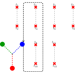
Fresh ancillas are prepared for steps to in the protocol given in Table 12 for encoded CNOT gate.
The procedure for implementing the encoded CNOT gate using color permuting twists is shown in Fig. 21. In Fig. 21(a), control, target and ancilla qubits encoded using a quadruple of twists is shown. We abbreviate control, target and ancilla qubits as C, T and A respectively. The ancilla is initialized in the state. Joint parity measurement by using dual qubit encoded using holes is shown in Fig. 21(b). This parity measurement is equivalent to doing the gate indicated in Equation (17) with target and ancilla qubits as control and the hole as target. Recall that braiding a dual qubit around twists encircled by logical operator realizes the gate in Equation (17) with twist qubit being control and dual qubit being target. Braiding hole as shown in Fig. 21(b) realizes the gate in Equation (17) between target qubit and ancilla qubit encoded using twists as control and qubit encoded using holes as target. The dual qubit is initialized in the state, braided around twists as shown and measured in the end. The measurement outcome reveals the parity of the operator . Similarly, to carry out parity measurement, a primal qubit encoded by holes is created and its logical and operators are interchanged by Pauli frame update. The primal qubit is initialized in the eigenstate of so that after Pauli frame update, the state of the primal qubit is , deformed around twists and measured in the end, see Fig. 21(c). This braiding realizes CNOT gate between control and ancilla qubits encoded using twists as control and the dual qubit encoded with holes as target. Finally, Hadamard on ancilla is performed by Pauli frame update and measurement in the basis is done as shown in Fig. 21(d).
We summarize the results of this section in the theorem below.
Theorem 24.
Using color permuting twists, single qubit Clifford gates are realized by Pauli frame update and CNOT gate by joint parity measurements with an ancilla.
So far we have discussed implementation of Clifford gates. To achieve universality, we need a non-Clifford gate. Non-Clifford gate is implemented using the technique of magic state distillation. A discussion on the implementation of non-Clifford gate is presented in Appendix D. The proposed protocol is a minor variation of the one given in Ref. Bravyi (2006).
VII Conclusion
In this paper, we have presented a systematic way to introduce charge permuting and color permuting twists in -colexes. We have also discussed the coding theoretic aspects of the same. We have shown that Clifford gates can be implemented using charge permuting twists by braiding alone. Encoded gates in the case of color permuting twists are implemented by a combination of Pauli frame update for single qubit gates and joint parity measurements with an ancilla for CNOT gate. Joint measurements are carried out by braiding holes around twists. To implement non-Clifford gate, we use magic state injection. A direction for future research could be to use techniques other than magic state distillation such as the one presented in Ref. Brown (2020) which could be used in the case of color codes with twists. Decoding color codes with twists is another fruitful area for further exploration.
Acknowledgement
We thank the reviewers for their comments which helped in improving the presentation of the paper. This research was supported by the Science and Engineering Research Board, Department of Science and Technology under Grant No. EMR/2017/005454.
Appendix
Appendix A Stabilizer commutation for charge permuting twists
As mentioned before, we have three types of faces in the lattice: twists (), faces through which domain wall passes through () and faces that are neither twists nor through which domain wall passes through (). When any two faces are not adjacent, then they do not share common vertices and hence the stabilizers defined on them commute. The stabilizer commutation in the case of adjacent faces needs to be checked. We have to check commutation between the six cases as listed below.
-
a)
and : When the two twists are adjacent, then they share exactly an edge. The Pauli operators corresponding to the two stabilizers are same on each of the common vertices. Hence, commutation follows.
-
b)
and : These faces share exactly an edge. The Pauli operators corresponding to the two stabilizers differ at each common vertex ( on twist and and on in the case of twists). Hence, commutation follows.
-
c)
and : The Pauli operators for the twist stabilizer and the normal face stabilizers differ on the common vertices shared between twist and normal faces, . Hence, they commute.
-
d)
and : The Pauli operators corresponding to the two stabilizers, and are different at each vertex. Note that all the faces have an even number of edges and hence these stabilizer generators anti-commute an even number of times. Therefore, these stabilizers commute.
-
e)
and : Along the common edge to these faces, the Pauli operators are either same or different. Hence, commutation follows.
-
f)
and : Stabilizers commute as the Pauli operators along the common edge are either same or different.
Appendix B Braiding of charge permuting twists
In this section, we show that the product of and as shown in Fig. 9 is equivalent to logical operator up to gauge, see Fig. 22. For convenience we drop the subscripts.
The deformation of logical operator to logical operator after braiding twists and is shown in Fig. 23. The string in Fig. 23(h) is logical operator up to a gauge operator.
Appendix C Existence of T-line
Lemma 25 (Existence of -lines).
Every pair of -color permuting twists created together are connected by a -line.
Proof.
Without loss of generality, assume that the twist faces have red color i.e. the twists permute the color of blue and green anyons. Consider a twist face in the pair, call it . Since twists are faces with an odd number of edges, it is not possible to color faces around them consistently with two colors. Therefore, there exists a pair of faces and which are adjacent and share the same color. Also, from the construction, one of these faces, say, is a modified face. The common edge to faces and is red and is incident on a normal red face, call it . Note that . As a consequence, faces around also cannot be colored consistently with two colors. Therefore, there exists a face such that . The face can be adjacent to either or . Assuming that it is adjacent to , we now have another pair of faces of the same color adjacent to each other. Continuing this argument by taking -colored faces connected by a -colored edge, we establish the existence of -lines in the presence of color permuting twists. ∎
Appendix D Non-Clifford gate
In this section we discuss the implementation of a non-Clifford gate. For both charge permuting and color permuting twists we use magic state distillation, see Table 13, to implement the non-Clifford gate. We have dropped the joint measurement in the protocol given in Ref. Bravyi (2006). Similarities and differences with previous protocols is given in Table 14.
| Protocol for gate | |
|---|---|
| (0) | Prepare the magic state . |
| (1) | Perform CNOT gate between data qubit and magic state |
| with the former as control and the latter as target. | |
| (2) | Measure the magic state qubit. |
| (3) | If , apply phase gate when measurement outcome is . |
| Step | Ref. Bravyi and Kitaev (2005) | Ref. Bravyi (2006) | Proposed protocol |
|---|---|---|---|
| Joint parity measurement | present | present | absent |
| CNOT gate | present | present | present |
| Ancilla measurement | absent | present | present |
Let be the state of the data qubit on which the non-Clifford gate has to be performed. The state of ancillary qubit prepared in magic state is . After implementing CNOT gate, the joint state is transformed to where
Upon measuring ancillary qubit, either the desired gate or its conjugate is implemented on the data qubit with equal probability. For , if the measurement outcome is , then the desired transformation on data qubit can be obtained by performing phase gate.
Magic state distillation protocols can be found in Refs. Bravyi and Haah (2012); Jones (2013); Haah et al. (2017); Chamberland and Noh (2020). Twists in color codes can be initialized in magic state by state injection Hastings and Geller (2015). The color code lattice with the encoded magic state is merged with the main lattice by lattice surgery Horsman et al. (2012). Then, the non-Clifford gate is implemented by performing the encoded versions of operations described in the protocol. After measuring the encoded ancilla qubit i.e. qubit initialized in the magic state, the sublattice containing the encoded ancilla qubit can be detached.
References
- Bombin and Martin-Delgado (2006) H. Bombin and M. A. Martin-Delgado, Phys. Rev. Lett. 97, 180501 (2006).
- Fowler (2011) A. G. Fowler, Phys. Rev. A 83, 042310 (2011).
- Landahl et al. (2011) A. J. Landahl, J. T. Anderson, and P. R. Rice, arXiv:1108.5738v1 [quant-ph] (2011).
- Horsman et al. (2012) C. Horsman, A. G. Fowler, S. Devitt, and R. V. Meter, New Journal of Physics 14, 123011 (2012).
- Landahl and Ryan-Anderson (2014) A. J. Landahl and C. Ryan-Anderson, arXiv:1407.5103v1 [quant-ph] (2014).
- Litinski (2019) D. Litinski, Quantum 3, 205 (2019).
- Kesselring et al. (2018) M. S. Kesselring, F. Pastawski, J. Eisert, and B. J. Brown, Quantum 2, 101 (2018).
- Hastings and Geller (2015) M. B. Hastings and A. Geller, Quantum Info. Comput. 15, 962 (2015).
- Kitaev (2003) A. Kitaev, Annals of Physics 303, 2 (2003).
- Bombin (2010) H. Bombin, Phys. Rev. Lett. 105, 030403 (2010).
- Kitaev and Kong (2012) A. Kitaev and L. Kong, Commun. Math. Phys 313,351-373(2012) (2012).
- You and Wen (2012) Y.-Z. You and X.-G. Wen, Phys. Rev. B 86, 161107 (2012).
- Brown et al. (2017) B. J. Brown, K. Laubscher, M. S. Kesselring, and J. R. Wootton, Phys. Rev. X 7, 021029 (2017).
- Gowda and Sarvepalli (2020) M. G. Gowda and P. K. Sarvepalli, Phys. Rev. A 102, 042616 (2020).
- Bombin (2011) H. Bombin, New Journal of Physics 13, 043005 (2011).
- Litinski and von Oppen (2018) D. Litinski and F. von Oppen, Phys. Rev. B 97, 205404 (2018).
- Bravyi (2006) S. Bravyi, Phys. Rev. A 73, 042313 (2006).
- Bhagoji and Sarvepalli (2015) A. Bhagoji and P. Sarvepalli, in 2015 IEEE International Symposium on Information Theory (ISIT) (2015) pp. 1109–1113.
- Bombin and Martin-Delgado (2009) H. Bombin and M. A. Martin-Delgado, Journal of Physics A: Mathematical and Theoretical 42, 095302 (2009).
- Anderson (2013) J. T. Anderson, Annals of Physics 330, 1 (2013).
- Diestel (2017) R. Diestel, Graph Theory, 5th Edition, Graduate texts in mathematics, Vol. 173 (Springer-Verlag, Berlin Heidelberg, 2017).
- Huffman and Pless (2003) W. C. Huffman and V. Pless, Fundamentals of Error-Correcting Codes (Cambridge University Press, Cambridge, 2003).
- Terhal (2015) B. M. Terhal, Rev. Mod. Phys. 87, 307 (2015).
- Nielsen and Chuang (2010) M. A. Nielsen and I. L. Chuang, Quantum Computation and Quantum Information: 10th Anniversary Edition (Cambridge University Press, Cambridge, 2010).
- Brown (2020) B. J. Brown, Science Advances 6 (2020), 10.1126/sciadv.aay4929.
- Bravyi and Kitaev (2005) S. Bravyi and A. Kitaev, Phys. Rev. A 71, 022316 (2005).
- Bravyi and Haah (2012) S. Bravyi and J. Haah, Phys. Rev. A 86, 052329 (2012).
- Jones (2013) C. Jones, Phys. Rev. A 87, 042305 (2013).
- Haah et al. (2017) J. Haah, M. B. Hastings, D. Poulin, and D. Wecker, Quantum 1, 31 (2017).
- Chamberland and Noh (2020) C. Chamberland and K. Noh, npj Quantum Information 6 (2020), 10.1038/s41534-020-00319-5.