Topological Boundary Constraints in Artificial Colloidal Ice
Abstract
The effect of boundaries and how these can be used to influence the bulk behaviour in geometrically frustrated systems are both long-standing puzzles, often relegated to secondary role. Here we use numerical simulations and ”proof of concept” experiments to demonstrate that boundaries can be engineered to control the bulk behavior in a colloidal artificial ice. We show that an antiferromagnetic frontier forces the system to rapidly reach the ground state (GS), as opposed to the commonly implemented open or periodic boundary conditions. We also show that strategically placing defects at the corners generates novel bistable states, or topological strings which result from competing GS regions in the bulk. Our results could be generalized to other frustrated micro and nanostructures where boundary conditions may be engineered with lithographic techniques.
In the thermodynamic limit the bulk properties of a statistical ensemble are no longer influenced by its boundaries. However, in frustrated spin systems the boundaries can induce configurations that propagate far into the bulk [1, 2]. Among several examples of frustrated systems in nature, the most representative one is spin ice [3, 4, 5], which can be considered the magnetic ”analogue” of the water ice [6]. Artificial spin ice systems (ASIs) based on lithographic engineering recently emerged as a versatile experimental platform to investigate geometric frustration effects [7]. An ASI is composed by a lattice of nanoscale ferromagnetic islands, arranged to induce frustration [8, 9, 10]. In contrast to natural magnets, ASI allows to directly visualize the spins arrangement, a feature that has been used to investigate the effect of disorder [11, 12, 13], thermalization [14, 15] and degeneracy in many geometries [16, 17, 18, 19, 20]. Alternative realizations include arrays of nanowires [21], patterned superconductors [22, 23], macroscopic magnets [24], Skyrmions in liquid crystals [25, 26], superconducting qbits [27], and colloidal particles in bistable potentials [28].
In such systems the presence of disorder or a finite temperature often prevents them from reaching the ground state (GS), and instead, they fall to a metastable state containing defects in form of charged vertices. These defects can be characterized by a topological charge and have a topological nature, since they can only be destroyed when annihilating with other defects of opposite charge. In the GS, the vertices satisfy the ice rule, that prescribes a minimization of the local charge, . While much attention has been placed on how temperature or external fields drive a system toward its GS, the role of boundaries in finite systems has been often overlooked. This is of especial importance when dealing with interacting magnetic system where the interaction energies are governed by long-range dipolar forces.
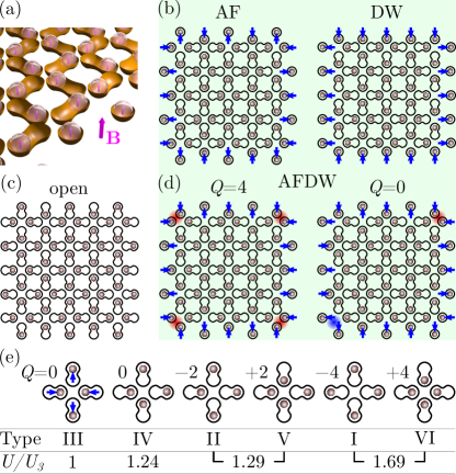
Here we show how boundaries can be engineered to control the bulk behaviour and the formation of topological states such as point defects and topological domain walls spanning the bulk. We demonstrate this concept here with an artificial colloidal ice, a system that recently emerged as a microscale soft-matter analogue to ASI [29]. Colloidal ice consists of an ensemble of paramagnetic colloids two dimensionally (D) confined by gravity in topographic double wells, where the particles may sit in two stable positions and an external magnetic field induces repulsive dipolar interactions, Fig. 1(a). One can assign a vector (analogous to a spin) to each well such that it points towards the vertex’s centre (spin ) or away from it (spin ), see Fig. 1. When arranged in a square lattice, one can classify six possible vertex types each of them with an associated topological charge , where is the number of particles and the lattice coordination number. For the square is . Thus, vertices of type III and type IV have and fulfil the ice rule, and type III gives rise to the GS. Topological defects are charged vertices with , or closed loops of type IV vertices, Fig. 1(e).
To simulate colloidal ice we perform Brownian dynamics, carefully parametrized to mimic the experiments [28]. We consider a D array of double wells, each filled by one paramagnetic colloid of diameter and magnetic volume susceptibility . The overdamped equation of motion for one colloid at position is:
| (1) |
where , is the force from the double well which is modelled as a bistable harmonic potential; more details are in the Supplemental Material [30]. The dipolar force acting on particle due to the neighbouring colloids is, , where the dipole moment induced by the external field , , and . To consider long-range dipolar interactions between the particles, we apply a large cutoff of 200m. Finally, represents a random force due to thermal fluctuation, with zero mean, and delta correlated, , with a temperature . Simulations are performed for different system sizes, ranging from to , where is the number of vertices along the side. We increase linearly up to mT, at a rate mT/s. For mT, the pair potential between two particles in the closest (farthest) place of two double wells is (). Our strategy to fix the boundary consists in placing a particle in a single harmonic well at a location such that it corresponds to a spin pointing or .
We consider four different situations: Two fixed boundary conditions, namely antiferromagnetic (AF) and domain wall (DW), illustrated in Fig. 1(b). In AF boundaries, colloids are placed alternately pointing and . However, flipping a subset of the colloids in an AF boundary can create defects that are topologically constrained to the inner region, as illustrated in Fig. 1(d). This is the basis of the Gauss’ law analogue introduced in [27] for a qbit system. As constructed, the AF state has a neutral charge at the boundaries. This charge neutrality is broken when a spin is changed from out to in and two defects are created on the AF state. With this strategy, we introduce in Fig. 1(d) the Antiferromagnetic Domain Wall (AFDW) where we mix AF boundaries with charged corners. This configuration produces different behavior with system size . With is even, two corners point in, two point out, and the charge is . Instead, with odd, the four corners point either in or out, and a total charge is locked inside the bulk. Further we also ran simulations with periodic boundaries, that are similar to previous simulation on particle based ice [31, 32], and with open boundaries, which represent the experiments with no fixed particles, Fig. 1(c).
To show how borders can be manipulated in experiments, we realize a square colloidal ice with antiferromagnetic domain walls. The system set-up has been described in [33]. Here we modify the boundaries of an isotropic lattice by adding non magnetic silica particles to the corresponding double wells. The silica particles induce local jamming, fixing the paramagnetic particle to a stable location, as shown below.
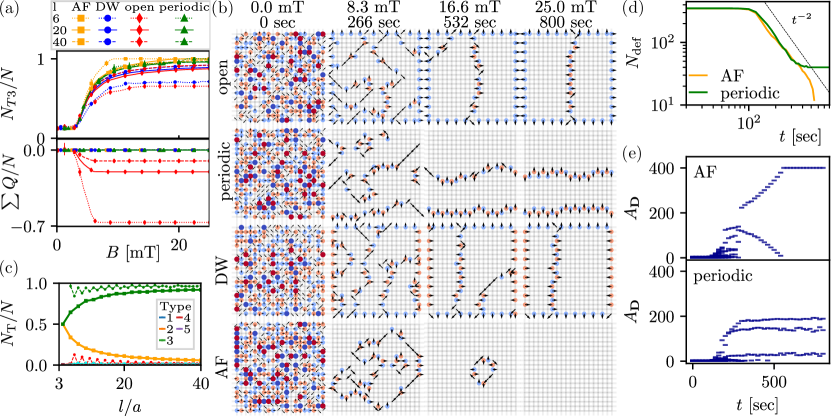
We start by showing in Fig. 2(a) how the four different boundary conditions influence the bulk behaviour in terms of the fractions of type III vertices (top) and average vertex charge (bottom). Both the open and DW frontiers show very similar trends, failing to reach the GS for all sizes. For these type of boundaries, the system accumulates charged defects at the boundaries, which are all negative for open boundaries, and positive (negative) for inward-pointing (outward-pointing) spins in the DW. Only open boundaries allow the appearance of a net non zero topological charge, which converges to a size dependent negative value at high field, as shown in the bottom of Fi g. 2(a). This effect can be appreciated also from the time evolution of the system in Fig. 2(b) and in video S1. Above mT, all the borders exhibit particles displaced toward the outer region (spins ), a radial polarization effect predicted in Ref. [34], Such effect arises since the analogy between spin and colloidal ice is broken near the boundaries due to the repulsive interactions between the particles, while in ASIs nanoislands interact due to in-plane dipolar forces. In contrast, periodic, AF and DW satisfy the conservation of topological charge for all field values and system sizes. As shown in Fig. 2(b), and videos S2 and S3, we find that a system with periodic or DW boundaries induce the formation of system-spanning domain walls, not allowed by the AF (video S4). These defect lines are very difficult to erase by increasing further, as they require the simultaneous flipping of large GS regions in the bulk. In a system with periodic boundaries, the parity of the domain walls is also topologically protected: when the boundaries are of even size (), defect lines can only appear in pairs. In contrast for odd values of , at least one defect line is always present. This effect appears also in Fig. 2(c), where the periodic boundaries exhibit a zigzag trend: odd lengths have an excess of type IV vertices which become less relevant as the boundary to bulk ratio becomes smaller. In contrast we found that AF boundaries can equilibrate to the GS faster and at lower fields since they restrict the phase space as predicted in Ref. [1]. The kinetics of the defects is analyzed in Fig. 2(d) for AF boundaries and compared to the periodic case. Both display coarsening dynamics with a power law scaling. This behavior can be also appreciated from the time evolution of the type III domains in Fig. 2(e). Initially, both systems create similar domain structures, but while a system with periodic boundaries falls to a metastable state with several smaller domains, the AF creates a single loop of defects that continuously shrink giving rise to the GS.
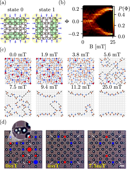
We now explore the behaviour when boundaries are fixed in the AFDW state. Fig. 3 shows a system with , where, if the energy of the type IV vertices were similar to that of type III, the charge would be contained in a single type I vertex, with four lines of type IV connecting it to the corners. However, due to line tension, as the applied field increases, it becomes more stable to break up the excess of charges and distribute them along two lines connecting the four corners. This leads to a symmetry breaking, where the system must choose whether to arrange the two connecting lines horizontally (state in Fig. 3(a,b) video S5) or vertically (state , video S6). We quantify this bistability using the order parameter , where is a sum over the vectors associated to charged vertices, and is an average calculated over all vertices. By definition, acquires a positive (negative) value of for defects arranged in the state (state ), Fig. 3(b). As shown in Fig. 3(c), we observe a bifurcation starting from mT. The process of choosing one of these two states develops via a coarsening of small type III domains and consequent reduction of the highly charged defects until three main domains are formed at mT. From here, the rest of the process consists of pulling, through line tension, the defect line toward the edges.
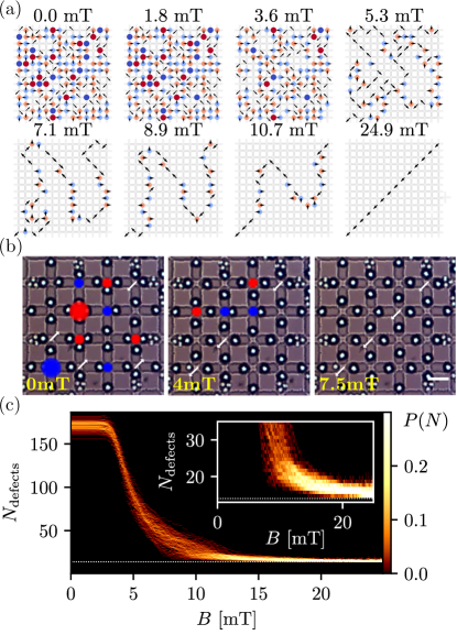
Another type of AFDW boundary condition can be imposed by introducing only two defects in opposite corners. This constraint creates two equal and incompatible type III regions that meet along the diagonal and are separated by a string of type IV vertices. The corresponding evolution from a disordered state is shown in Fig. 4(a,b) and in video S7. In the simulations, after mT, the system nucleates two type III regions which coarsen to the two final domains at mT. The final straightening process of the topological string results from line tension, as also confirmed by experiments, Fig. 4(c). However, we find that this defect line is not always completely stretched, and defects might appear in the form of small distortions connected by a string of type IV vertices, parallel and pointing along the opposite direction from the main defect line (Fig. 1 of the SI [30]). We capture this effect by measuring in Fig. 4(c) the distribution of the number of defects. As the field increases, the system gets rid of all non type III vertices, until it reaches a steady-state close to the topologically protected minimum number of defects, which is equal to (dotted white line in Fig. 4(c)). Nevertheless, the inset shows that such minimum value is not reached by many of the realizations, since many systems fall to a state with a small number of defects distributed along the domain wall, and deviating from the diagonal.
To conclude, we show how to engineer different boundary conditions to control the bulk behaviour in a geometrically frustrated soft matter system. We demonstrate this concept with an artificial colloidal ice combining numerical simulation and experimental realizations. Topological defects placed at the boundaries propagate inside the bulk, forming bistable states with symmetry breaking, or topologically protected strings. The fact that the observed phenomena display a topologically protected nature suggest that they could be observed on other systems such as nanomagnetic artificial ice. This could be tested experimentally for example by using lithography to design smaller and compact islands such as ferromagnetic cubes [35], cylinders [36] or disks [37] at the system edges to impose a desired bulk configuration. From the technological perspective, writing or erasing defect lines in the GS region can be used to freeze information into the system by applying a bias during the equilibration process [38].
Acknowledgements.
We thank Demian Levis and Leticia Cugliandolo for pointing us towards their work on Arctic regions in vertex models. Experiments were realised with the help of the MicroFabSpace and Microscopy Characterization Facility at IBEC. This project has received funding from the European Research Council (ERC) under the European Union’s Horizon 2020 research and innovation programme (grant agreement no. 811234). P. T. acknowledge support the Generalitat de Catalunya under Program “ICREA Acadèmia”.References
- Han [2009] Y. Han, Phase-space networks of geometrically frustrated systems, Phys. Rev. E 80, 051102 (2009).
- Han [2010] Y. Han, Phase-space networks of the six-vertex model under different boundary conditions, Phys. Rev. E 81, 041118 (2010).
- Harris et al. [1997] M. J. Harris, S. T. Bramwell, D. F. McMorrow, T. Zeiske, and K. W. Godfrey, Geometrical frustration in the ferromagnetic pyrochlore , Phys. Rev. Lett. 79, 2554 (1997).
- Ramirez et al. [1999] A. P. Ramirez, A. Hayashi, R. J. Cava, R. Siddharthan, and B. S. Shastry, Zero-point entropy in ‘spin ice’, Nature 399, 333–335 (1999).
- Bramwell and Gingras [2001] S. T. Bramwell and M. J. P. Gingras, Spin ice state in frustrated magnetic pyrochlore materials, Science 294, 1495 (2001).
- Giauque and Stout [1936] W. Giauque and J. Stout, The entropy of water and the third law of thermodynamics. the heat capacity of ice from 15 to 273 k, J. Am. Chem. Soc. 58, 1144 (1936).
- Wang et al. [2006] R. F. Wang, C. Nisoli, R. S. Freitas, J. Li, W. McConville, B. J. Cooley, M. S. Lund, N. Samarth, C. Leighton, V. H. Crespi, and P. Schiffer, Artificial ‘spin ice’ in a geometrically frustrated lattice of nanoscale ferromagnetic islands, Nature 439, 303 (2006).
- Nisoli et al. [2013] C. Nisoli, R. Moessner, and P. Schiffer, Colloquium : Artificial spin ice: Designing and imaging magnetic frustration, Rev. Mod. Phys. 85, 1473 (2013).
- Cugliandolo [2017] L. F. Cugliandolo, Artificial spin ice and vertex models, J Stat Phys 167, 499 (2017), arXiv:1701.02283 .
- Skjærvø et al. [2020] S. H. Skjærvø, C. H. Marrows, R. L. Stamps, and L. J. Heyderman, Advances in artificial spin ice, Nat. Rev. Phys 2, 13 (2020).
- Branford et al. [2012] W. R. Branford, S. Ladak, D. E. Read, K. Zeissler, and L. F. Cohen, Emerging chirality in artificial spin ice, Science 335, 1597 (2012).
- Chern et al. [2014] G.-W. Chern, C. Reichhardt, and C. J. O. Reichhardt, Avalanches and disorder-induced criticality in artificial spin ices, New J. Phys. 16, 063051 (2014).
- Drisko et al. [2017] J. Drisko, T. Marsh, and J. Cumings, Topological frustration of artificial spin ice, Nat. Comm. 8, 14009 (2017).
- Morgan et al. [2011] J. P. Morgan, A. Stein, S. Langridge, and C. H. Marrows, Thermal ground-state ordering and elementary excitations in artificial magnetic square ice, Nat. Phys. 7, 75–79 (2011).
- Farhan et al. [2013] A. Farhan, P. M. Derlet, A. Kleibert, A. Balan, R. V. Chopdekar, M. Wyss, J. Perron, A. Scholl, F. Nolting, and L. J. Heyderman, Direct observation of thermal relaxation in artificial spin ice, Phys. Rev. Lett. 111, 057204 (2013).
- Wang et al. [2016] Y.-L. Wang, Z.-L. Xiao, A. Snezhko, J. Xu, L. E. Ocola, R. Divan, J. E. Pearson, G. W. Crabtree, and W.-K. Kwok, Rewritable artificial magnetic charge ice, Science 352, 962 (2016).
- Gilbert et al. [2016] I. Gilbert, Y. Lao, I. Carrasquillo, L. O’Brien, J. D. Watts, M. Manno, C. Leighton, A. Scholl, C. Nisoli, and P. Schiffer, Emergent reduced dimensionality by vertex frustration in artificial spin ice, Nat. Phys. 12, 162–165 (2016).
- Canals et al. [2016] B. Canals, I.-A. Chioar, V.-D. Nguyen, M. Hehn, D. Lacour, F. Montaigne, A. Locatelli, T. O. Menteş, B. S. Burgos, and N. Rougemaille, Fragmentation of magnetism in artificial kagome dipolar spin ice, Nat. Communications 7, 11446 (2016).
- Perrin et al. [2016] Y. Perrin, B. Canals, and N. Rougemaille, Extensive degeneracy, coulomb phase and magnetic monopoles in artificial square ice, Nature 540, 410 (2016).
- Shi et al. [2016] D. Shi, Z. Budrikis, A. Stein, S. A. Morley, P. D. Olmsted, G. Burnell, and C. H. Marrows, Frustration and thermalization in an artificial magnetic quasicrystal, Nat. Phys. 14, 309–314 (2016).
- Mengotti et al. [2011] E. Mengotti, L. J. Heyderman, A. F. Rodríguez, F. Nolting, R. V. Hügli, and H.-B. Braun, Real-space observation of emergent magnetic monopoles and associated Dirac strings in artificial kagome spin ice, Nature Phys 7, 68 (2011).
- Libál et al. [2009] A. Libál, C. J. O. Reichhardt, and C. Reichhardt, Creating Artificial Ice States Using Vortices in Nanostructured Superconductors, Phys. Rev. Lett. 102, 237004 (2009).
- Latimer et al. [2013] M. L. Latimer, G. R. Berdiyorov, Z. L. Xiao, F. M. Peeters, and W. K. Kwok, Realization of Artificial Ice Systems for Magnetic Vortices in a Superconducting MoGe Thin Film with Patterned Nanostructures, Phys. Rev. Lett. 111, 067001 (2013).
- Mellado et al. [2012] P. Mellado, A. Concha, and L. Mahadevan, Macroscopic Magnetic Frustration, Phys. Rev. Lett. 109, 257203 (2012).
- Ma et al. [2016] F. Ma, C. Reichhardt, W. Gan, C. J. O. Reichhardt, and W. S. Lew, Emergent Geometric Frustration of Artificial Magnetic Skyrmion Crystals, Phys. Rev. B 94, 144405 (2016), arXiv:1608.06733 .
- Duzgun and Nisoli [2019] A. Duzgun and C. Nisoli, Artificial Spin Ice of Liquid Crystal Skyrmions, arXiv:1908.03246 [cond-mat] (2019), arXiv:1908.03246 [cond-mat] .
- King et al. [2020] A. D. King, C. Nisoli, E. D. Dahl, G. Poulin-Lamarre, and A. Lopez-Bezanilla, Quantum Artificial Spin Ice, arXiv:2007.10555 [cond-mat, physics:quant-ph] (2020), arXiv:2007.10555 [cond-mat, physics:quant-ph] .
- Ortiz-Ambriz and Tierno [2016] A. Ortiz-Ambriz and P. Tierno, Engineering of frustration in colloidal artificial ices realized on microfeatured grooved lattices, Nat Commun 7, 10575 (2016).
- Ortiz-Ambriz et al. [2019] A. Ortiz-Ambriz, C. Nisoli, C. Reichhardt, C. J. O. Reichhardt, and P. Tierno, Colloquium : Ice rule and emergent frustration in particle ice and beyond, Rev. Mod. Phys. 91, 041003 (2019).
- [30] See EPAPS Document No.xxxx which includes two supplementary videos and images to support the main results.
- Libál et al. [2006] A. Libál, C. Reichhardt, and C. J. O. Reichhardt, Realizing colloidal artificial ice on arrays of optical traps, Phys. Rev. Lett. 97, 228302 (2006).
- Libál et al. [2018] A. Libál, C. Nisoli, C. J. O. Reichhardt, and C. Reichhardt, Inner phases of colloidal hexagonal spin ice, Phys. Rev. Lett. 120, 027204 (2018).
- Oğuz et al. [2020] E. C. Oğuz, A. Ortiz-Ambriz, H. Shem-Tov, E. Babià-Soler, P. Tierno, and Y. Shokef, Topology Restricts Quasidegeneracy in Sheared Square Colloidal Ice, Phys. Rev. Lett. 124, 238003 (2020).
- Nisoli [2018] C. Nisoli, Unexpected Phenomenology in Particle-Based Ice Absent in Magnetic Spin Ice, Phys. Rev. Lett. 120, 167205 (2018).
- Louis et al. [2018] D. Louis, D. Lacour, M. Hehn, V. Lomakin, T. Hauet, and F. Montaigne, A tunable magnetic metamaterial based on the dipolar four-state potts model, Nature Mater. 17, 1076–1080 (2018).
- Sklenar et al. [2019] J. Sklenar, Y. Lao, A. Albrecht, J. D. Watts, C. Nisoli, G.-W. Chern, and P. Schiffer, Field-induced phase coexistence in an artificial spin ice, Nat. Physcs 15, 191–195 (2019).
- Streubel et al. [2018] R. Streubel, N. Kent, S. Dhuey, A. Scholl, S. Kevan, and P. Fischer, Spatial and temporal correlations of xy macro spins, Nano Lett. 15, 191–195 (2018).
- Wang et al. [2018] Y.-L. Wang, X. Ma, J. Xu, Z.-L. Xiao, A. Snezhko, R. Divan, L. E. Ocola, J. E. Pearson, B. Janko, and W.-K. Kwok, Switchable geometric frustration in an artificial-spin-ice–superconductor heterosystem, Nat. Nanothechnology 13, 560 (2018).