Force-and-moment-based Model Predictive Control for Achieving Highly Dynamic Locomotion on Bipedal Robots
Abstract
In this paper, we propose a novel framework on force-and-moment-based Model Predictive Control (MPC) for dynamic legged robots. Specifically, we present a formulation of MPC designed for 10 degree-of-freedom (DoF) bipedal robots using simplified rigid body dynamics with input forces and moments. This MPC controller will calculate the optimal inputs applied to the robot, including 3-D forces and 2-D moments at each foot. These desired inputs will then be generated by mapping these forces and moments to motor torques of 5 actuators on each leg. We evaluate our proposed control design on physical simulation of a 10 degree-of-freedom (DoF) bipedal robot. The robot can achieve fast walking speed up to on rough terrain, with accurate velocity tracking. With the same control framework, our proposed approach can achieve a wide range of dynamic motions including walking, hopping, and running using the same set of control parameters.
I Introduction
The motivation of studying bipedal robots is widely promoted by commercial and sociological interests [1]. The desired outcomes of bipedal robot applications range from replacing humans in hazardous operations [2], in which it requires highly dynamic robots in unknown complex terrains, to the development of highly functional bipedal robot applications in the medical field and rehabilitation processes such as recent development in research of powered lower-limb prostheses for the disabled [3].
There are many control strategies that can be used for control of bipedal robots, such as Zero-Moment-Point (ZMP) or using spring-loaded inverted pendulum (SLIP) model [4, 5, 6]. Both methods have had success in maintaining stable locomotion of bipedal robots (e.g. [4, 6]). Hybrid Zero Dynamics method is another control framework utilizes input-output linearization, a non-linear feedback controller, with virtual constraints that allows dynamic walking on under-actuated bipedal robots [1, 7, 8]. Recently, force-based MPC control was introduced for dynamic quadruped robots [9], allowing the robot to perform a wide range of dynamic gaits with robustness to rough terrains. One advantage of the MPC framework in dynamic locomotion is that the controller can predict future motions that may cause instability due to under-actuation and stabilize the system by solving for optimal inputs based on the prediction.
MPC has been also utilized in the control of bipedal robots through various approaches. The control framework proposed in [10] applies MPC to minimize the values of rapidly exponentially stabilizing control Lyapunov function (RES-CLF) in a Human-Inspired Control (HIC) approach. A revisited ZMP Preview Control scheme presented in [11] attempts to solve an optimal control problem by MPC that finds an optimal sequence of jerks of robot center of mass (CoM). However, these approaches are either based on position control to track a joint trajectory resulting from optimization; or tend to address the step-by-step planning problem. In this work, we focus on a real-time feedback control approach that can handle a wide range of walking gaits, without relying on offline trajectory optimization.
Inspired by the successful force-based MPC approach for quadruped robots presented in [9], in this paper, we propose a new control framework that utilizes MPC to solve for optimal ground reaction forces and moments to achieve dynamic motion on bipedal robots. We investigate different models that can be used for the MPC framework and introduce the formulation that works most effectively on our bipedal robot model. Our proposed approach allows a 10-DOF bipedal robot to perform high-speed and robust locomotion on rough terrain. We implement and validate our controller design in a high-fidelity physical simulation that is constructed in MATLAB and Simulink with the software dependency of Spatial v2.
The main contributions of the paper are as follows:
-
•
We proposed a new framework of force-and-moment-based MPC for 10-DoF bipedal robot locomotion.
-
•
We investigate different models of rigid body dynamics that can be used for the MPC framework. The most effective model is then used in our proposed approach.
-
•
The proposed MPC framework allows 3-D dynamic locomotion with accurate velocity tracking.
-
•
Our control framework can enable a wide range of dynamic locomotion such as fast walking, hopping, and running using the same set of control parameters.
-
•
Thanks to using the force-and-moment based control inputs, our approach is also robust to rough terrain. We have successfully demonstrated the problem of fast walking with the velocity of on rough terrain. The rough terrain consists of stairs with a maximum height of and a maximum difference of between two consecutive stairs.
The rest of the paper is organized as follows. Section II introduces the model design and physical parameters of the bipedal robot. Simulation methods and control architecture are also provided in this section. Section III presents the dynamics and controller choices, design, and formulation of the proposed force-and-moment-based MPC controller. Some result highlights are presented in Section IV along with an analysis on controller performance in various dynamic motions.
II Bipedal Robot Model and Simulation
II-A Robot Model
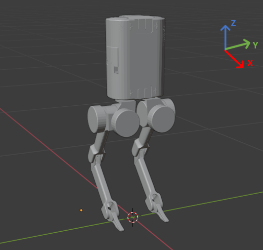
In this section, we present the robot model that will be used throughout the paper. A 10 DoF bipedal robot consists of 5 joint actuation each leg (see Fig. 2(a)). Commonly, a 10 DoF bipedal robot has abduction (ab) and hip joints that allow 3-D rotation and ankle joints that allow double-leg-support standing (e.g., [12, 13]).
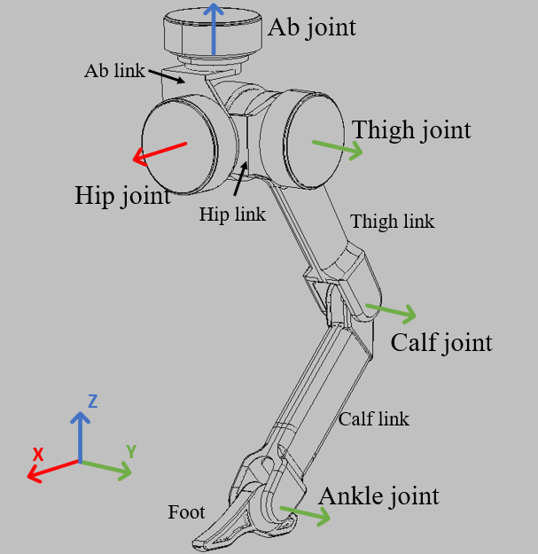
The design of our bipedal consists of the robot body, ab link, hip link, thigh link, calf link, and foot link (see Fig. 2(b) for the definition of the leg configuration and Table I for physical parameters). The robot body is adopted from the Unitree A1 robot, in a vertical configuration. The joint actuator modeled in this robot design is the Unitree A1 modular actuator, which is a lightweight and powerful torque-controlled motor that is suitable for mini legged robots (see Table LABEL:tab:motor for the parameters of the actuator).
| Parameter | Symbol | Value | Units |
|---|---|---|---|
| Mass | 11.84 | ||
| Body Inertia | 0.0443 | ||
| 0.0535 | |||
| 0.0214 | |||
| Body Length | 0.114 | ||
| Body Width | 0.194 | ||
| Body Height | 0.247 | ||
| Thigh and Calf Lengths | 0.2 | ||
| Foot Length | 0.09 | ||
| 0.05 |
| Parameter | Value | Units |
|---|---|---|
| Max Torque | 33.5 | |
| Max Joint Speed | 21 |
II-B Simulation
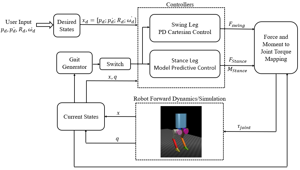
The bipedal robot simulation is built primarily in MATLAB Simulink using Spatial v2 package [14]. Fig. 3 shows the diagram for our control architecture and also the representation of our simulation software.
The simulation software requires the user to input desired states at the beginning of the simulation. The desired states form a column vector that consist desired body center of mass (CoM) position , desired body CoM velocity , desired rotation matrix (resized to 9×1 vector), and desired angular velocity of robot body.
III Dynamics and Control
III-A Simplified Dynamics
In this Section, we investigate different dynamic models that can be used in our MPC control framework. While the whole-body dynamics of the bipedal robot are highly non-linear, we are interested in using simplified rigid-body dynamics to guarantee that our MPC controller can be solved effectively in real-time. In addition, in order to enable the capability of absorbing frequent and hard impacts from dynamic locomotion, the design of bipedal robots also requires lightweight limbs and connections. This has allowed the weight and rotation inertia of each link part to be very small compared to the body weight and rotation inertia. Hence, the effect of leg links in the robot dynamics may be neglected, forming simplified rigid-body dynamics [15, 16]. This is also a common assumption in many legged robots’ controller designs [17, 18].
There are three simplified dynamics models that we have considered and tested, shown in Fig. 4. The main difference between these three options is the number of contact points on each foot, contact location, and contact force and moment formation at each contact point. Model 1 resembles the simplified dynamics choice for quadruped robots mentioned in [16], with 4 contact points exerting 3-D contact forces. However, with this dynamics model applied to our 10-DoF bipedal robot, under rotation motions testings in simulation, the robot is unable to perform pitch motion properly. Model 2 is improved and further simplifies the contact points. However, with this simplified dynamics model, in simulation validation process, the robot is unable to perform roll motion correctly. Hence, we proposed model 3 that excludes external moment around -axis, and contains only 3-D contact forces and 2-D moments around and -axis. This model has allowed the robot to perform all 3-D rotations effectively. Hence, model 3 is chosen to be the final simplified dynamics design in this framework. More details about the validation of this decision process is shown in Section IV. The detailed derivation of the model 3 dynamics is presented as follows.
The bipedal model in this paper has two legs that both consists of 5 DoF. Commonly, the external contact forces applied to the robot are only limited to 3-D forces in many legged-robot dynamics (e.g., [12, 15]). However, thanks to the additional hip and ankle joint actuation, the external moments can also be included in the robot dynamics, forming a linear relationship between robot body’s acceleration , rate of change in angular momentum about CoM [18], and contact force and moments shown as follows:
| (5) |
where
| (7) |
| (9) |
| (13) |
The term denotes the distance vector from the robot body CoM location to the foot position in the world coordinate; and represents the skew-symmetric matrix representing the cross product of . Here, can be approximated as (as discussed in [15]), where stands for the centroid rotation inertia of robot body in the world frame and represents the angular velocity of robot body in the world frame [16, 18].
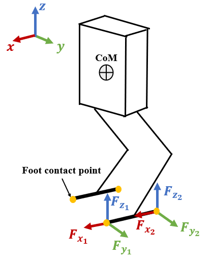
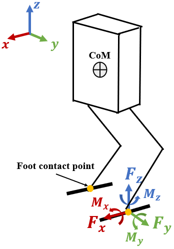
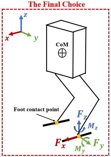
Equation (5) to (13) describes the simplified dynamics model 3. This model only used 5 force and moment inputs which are directly mapped to 5 joint torques in each leg.
We use rotation matrix as a state variable to represent the orientation of the robot body, which can be also directly converted to Euler Angles. We linearize the rotation matrix by approximating the angular velocity in terms of Euler angle , where is roll angle, is pitch angle, and is yaw angle. With the assumption of small roll and pitch angles [9], the relation of the rate of change of and angular velocity in the world coordinate can be approximated as:
| (18) |
Hence the kinematic constraint of the Euler angles is obtained as follow:
| (19) |
Combing the approximated orientation dynamics and the translation dynamics, the simplified dynamics of the robot can be written as:
| (20) |
where
| (21) |
| (22) |
III-B MPC Formulation
Having discussed the dynamics model, we now present details about the formulation of our MPC controller.
The linearized dynamics in (24) can be represented in a discrete-time form at each time step
| (25) |
where discrete time matrix is a constant matrix computed from using a average yaw value during entire reference trajectory; and matrix is computed from , using the desired values of average yaw and foot location. The only exception is that at the first time step, is computed from current states of the robot instead of reference trajectory.
An MPC problem with a finite horizon length can be written in the following standard form:
| (26) |
| s.t. | (27) |
| (28) |
| (29) |
In (26), and are system states and control inputs at time step . Note that the MPC prediction is computed based on the measured states of current step (i.e. ). and are matrices defining the weights of each state and control input variable. and in (27) are the discrete-time system dynamic constraints from (25). ,, and in (28) represents the inequality constraints of the MPC problem. in (29) represents the equality constraints. In this problem, the equality constraint governs the optimal control input from MPC controller is a zero vector for swing foot.
The MPC controller solves the optimal ground contact force and moment with respect to dynamic constraints (27) and the following inequality constraints:
| (30) | |||
| (31) | |||
| (32) |
Here, (III-B) governs the contact forces in and direction are within the friction pyramid, with being the friction coefficient. The contact forces in -direction should also fall within the upper and lower bounds of force (31), where the lower bound is positive to maintain contact with the ground. It is also important to restrict the joint torques to be within the saturation of the physical motor (32).
III-C QP Formulation
With the linear dynamics in Section III-A and the MPC formulation in Section III-B, our controller can be formulated as a quadratic program (QP) that can be solved effectively in real-time.
Firstly, the dynamic constraints (24) for the entire MPC prediction horizon can be written as:
| (33) |
where is a column vector containing system states for the next horizons, and is a column vector containing optimal control inputs of current state and next horizons, at time step . The MPC controller now can be written as the following QP form:
| (34) | ||||
| s.t. | (35) | |||
| (36) |
where and are inequality constraint matrices, and are equality constraint matrices, and
| (37) | |||
| (38) |
Diagonal matrices and are the weights for the rate of change of state variables and force/moment magnitude.
The resulting controller input of each leg from QP problem is mapped to its joint torques by
| (39) |
where is the Jacobian matrix of th leg
| (40) |
with and being the linear velocity and angular velocity components of .
III-D Swing Leg Control
As discussed earlier in this section, due to equality constraints, the robot leg that is under the swing phase does not exert ground contact forces and therefore is not under the control of force-and-moment-based MPC. In order to control the leg and foot position in each gait cycle, the desired foot trajectory is under control in the Cartesian space with a PD position controller. The gait sequence is purely based on timing and the gait cycle length is currently set at . We obtain the current foot location using forward kinematics. Foot velocity is computed by:
| (41) |
where is the joint velocity state-feedback of each leg at time step .
The desired foot location in the world frame is determined by the foot placement policy employed in [9]:
| (42) |
where is the hip joint location in the world frame and is the time that stance foot spends on the ground during one gait cycle.
The swing leg force can be computed by treating the foot attached to a virtual spring-damper system [19]. The foot weight is reasonable to be neglected since it is very small compared to the robot body [15]. Following the PD control law, the foot force can be written as:
| (43) |
where and are PD control gains, or spring stiffness and damping coefficient of the virtual spring-damper system.
Similar to (39), the joint torque can be computed by:
| (44) |
With Cartesian PD control, the swing leg can move and be controlled to follow desired foot placement trajectory. The gait generator decides either the robot leg is in the stance phase or swing phase in a fixed gait cycle and assigns the appropriate controller to the corresponding leg. Now the robot has both swing and stance leg control, it is ready to test the MPC in simulation.
IV Simulation Results
In this section, we present numerical validation of our proposed approach for different dynamic locomotion. The reader is encouraged to watch the supplemental video111https://youtu.be/Z2s4iuYkuvg for the visualization of our results. For our simulation, the bipedal robot model and ground contact model are set up in MATLAB with Spatial v2 software. The MPC sampling frequency is set to while the simulation is run at . One gait cycle that contains 10 horizons is predicted at each time step in MPC, in which each gait cycle is fixed at . This prediction length has been also used in [9].
The weighting factors in (26) are tuned to balance the performance between different control actions. In our simulation, we use , , , and . The rest weighting factors in remains at 1.


IV-A Validation of Simplified Dynamics
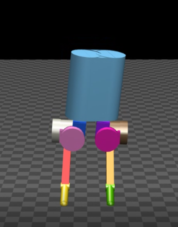
First, we present the simulation results of simple rotation motions during standing with both legs on the ground to validate the claim in Section III that for the simplified dynamics used for control design, model 3 is a superior choice over model 1 and model 2.
As mentioned in Section III, the simplified dynamics model 1 is unable to perform pitch motion. It is shown in Fig. 5, a pitch motion comparison between using simplified dynamics model 1 and model 3. The latter one is what we ultimately chose to use in MPC formulation. It is observed that the simulation result with model 1 does not respond to desired pitch input, whereas model 3 can perform pitch motion.
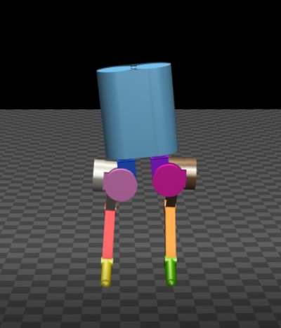
We then further simplified model 1 and added 3-D moment inputs to each contact point to form simplified dynamics model 2. However, in the roll motion test, the response with model 2 is incorrect to desired roll input and it also shows a deviation in yaw angle as shown in Fig. 6. With model 3, the robot simulation succeed in the roll motion test. Therefore, we decide to use model 3 for our proposed approach. Following are simulation results for walking and hopping motion using MPC control for model 3.
IV-B Velocity Tracking
In this simulation, we test the MPC performance in forward walking motion(positive -direction) with time-varying desired speed and the desired CoM height of . The velocity tracking plot is shown in Fig. 7, the actual response curve with MPC shows a good tracking performance. The velocity response has a maximum deviation of compared to the desired input. Besides walking forward, we also have successful simulation results and demonstrations in walking sideways and diagonally. This result validates the effectiveness of our proposed control framework in realizing 3D dynamic locomotion for bipedal robots.

IV-C High-velocity Walking in Rough Terrain
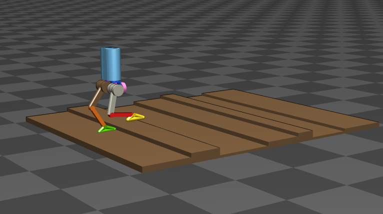
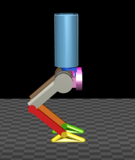
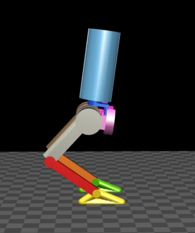
We also validated the controller performance in rough terrain locomotion at high speed. Specifically, the robot is commanded to walk through a -meter-long rough terrain formed by stairs with various heights and lengths. The stair heights range from to with a maximum height difference of between two consecutive stairs. To validate the feasibility and potential of MPC locomotion through rough terrain, the robot is commanded to follow a high desired velocity . A snapshot of this simulation is provided in Fig. 1.
Plots of CoM location, velocity, and body orientation are shown in Fig. 8 and Fig. 9. It can be observed that the CoM location and orientation during this simulation maintain small tracking errors. The joint torques (shown in Fig. 11) during this entire simulation are in reasonable ranges and satisfy the torque saturation shown in Table LABEL:tab:motor.


IV-D Bipedal Hopping
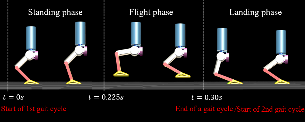
On top of the rotation and walking simulations presented earlier in this section, we have also implemented other gaits such as hopping. The hopping gait consists of a double support phase and a flight phase during the last quarter of each gait. A hopping gait illustration is shown in Fig. 12. It can be observed that during hopping motion, the robot is in a clear flight phase. This result validated that our proposed approach can work effectively for different dynamic locomotion on bipedal robots. We plan to optimize the MPC formulation in future work to enable faster and more aggressive motions.
V Conclusions
In conclusion, we introduced an effective approach of force-and-moment-based Model Predictive Control to achieve highly dynamic locomotion on rough terrains for 10 degrees of freedom bipedal robots. Our framework also allows the robot to achieve a wide range of 3-D motions using the same control framework with the same set of control parameters. The convex MPC formulation can be translated into a Quadratic Program problem and solved effectively in real-time of less than . We explore and find the most suitable dynamics model for the control framework and we have presented successful walking simulations with time-varying velocity input, rough-terrain locomotion with high velocity and results in different dynamic gaits. Simulation results have indicated that the control performance in the velocity tracking test has a maximum deviation of compared to the desired input. In the rough terrain test, the robot is able to walk through rough terrain with various heights while maintaining a high forward walking velocity at . Future work will include extending the approach for more aggressive motion and experimental validation of the framework on the robot hardware.
References
- [1] E. R. Westervelt, J. W. Grizzle, C. Chevallereau, J. H. Choi, and B. Morris, Feedback control of dynamic bipedal robot locomotion. CRC press, 2018.
- [2] Y. Chen, A. Pandey, Z. Deng, A. Nguyen, R. Wang, T. Liu, P. Thonapalin, Q. Nguyen, and S. Gupta, “A semi-autonomous quadruped robot for performing disinfection in cluttered environments,” in 2021 ASME Mechanism and Robotics Conference, IEEE, 2021.
- [3] H. Zhao, J. Horn, J. Reher, V. Paredes, and A. D. Ames, “First steps toward translating robotic walking to prostheses: a nonlinear optimization based control approach,” Autonomous Robots, vol. 41, no. 3, pp. 725–742, 2017.
- [4] A. D. Ames, E. A. Cousineau, and M. J. Powell, “Dynamically stable bipedal robotic walking with nao via human-inspired hybrid zero dynamics,” in Proceedings of the 15th ACM international conference on Hybrid Systems: Computation and Control, pp. 135–144, 2012.
- [5] S. Kajita, M. Morisawa, K. Harada, K. Kaneko, F. Kanehiro, K. Fujiwara, and H. Hirukawa, “Biped walking pattern generator allowing auxiliary zmp control,” in 2006 IEEE/RSJ International Conference on Intelligent Robots and Systems, pp. 2993–2999, IEEE, 2006.
- [6] P. Holmes, R. J. Full, D. Koditschek, and J. Guckenheimer, “The dynamics of legged locomotion: Models, analyses, and challenges,” SIAM review, vol. 48, no. 2, pp. 207–304, 2006.
- [7] Q. Nguyen, X. Da, J. Grizzle, and K. Sreenath, “Dynamic walking on stepping stones with gait library and control barrier,” in Workshop on Algorithimic Foundations of Robotics, 2016.
- [8] Q. Nguyen, A. Agrawal, X. Da, W. C. Martin, H. Geyer, J. W. Grizzle, and K. Sreenath, “Dynamic walking on randomly-varying discrete terrain with one-step preview.,” in Robotics: Science and Systems, vol. 2, 2017.
- [9] J. Di Carlo, P. M. Wensing, B. Katz, G. Bledt, and S. Kim, “Dynamic locomotion in the mit cheetah 3 through convex model-predictive control,” in 2018 IEEE/RSJ International Conference on Intelligent Robots and Systems (IROS), pp. 1–9, IEEE, 2018.
- [10] M. J. Powell, E. A. Cousineau, and A. D. Ames, “Model predictive control of underactuated bipedal robotic walking,” in 2015 IEEE International Conference on Robotics and Automation (ICRA), pp. 5121–5126, IEEE, 2015.
- [11] P.-B. Wieber, “Trajectory free linear model predictive control for stable walking in the presence of strong perturbations,” in 2006 6th IEEE-RAS International Conference on Humanoid Robots, pp. 137–142, IEEE, 2006.
- [12] G. T. Levine and N. M. Boyd, “Blackbird: Design and control of a low-cost compliant bipedal robot,”
- [13] Y. Gong, R. Hartley, X. Da, A. Hereid, O. Harib, J.-K. Huang, and J. Grizzle, “Feedback control of a cassie bipedal robot: Walking, standing, and riding a segway,” in 2019 American Control Conference (ACC), pp. 4559–4566, IEEE, 2019.
- [14] R. Featherstone, Rigid body dynamics algorithms. Springer, 2014.
- [15] Q. Nguyen, M. J. Powell, B. Katz, J. Di Carlo, and S. Kim, “Optimized jumping on the mit cheetah 3 robot,” in 2019 International Conference on Robotics and Automation (ICRA), pp. 7448–7454, IEEE, 2019.
- [16] G. Bledt, M. J. Powell, B. Katz, J. Di Carlo, P. M. Wensing, and S. Kim, “Mit cheetah 3: Design and control of a robust, dynamic quadruped robot,” in 2018 IEEE/RSJ International Conference on Intelligent Robots and Systems (IROS), pp. 2245–2252, IEEE, 2018.
- [17] M. Focchi, A. Del Prete, I. Havoutis, R. Featherstone, D. G. Caldwell, and C. Semini, “High-slope terrain locomotion for torque-controlled quadruped robots,” Autonomous Robots, vol. 41, no. 1, pp. 259–272, 2017.
- [18] B. J. Stephens and C. G. Atkeson, “Push recovery by stepping for humanoid robots with force controlled joints,” in 2010 10th IEEE-RAS International conference on humanoid robots, pp. 52–59, IEEE, 2010.
- [19] G. Chen, S. Guo, B. Hou, and J. Wang, “Virtual model control for quadruped robots,” IEEE Access, vol. 8, pp. 140736–140751, 2020.