Blockwise Phase Rotation-Aided Analog Transmit Beamforming for 5G mmWave Systems

Md. Abdul Latif Sarker, Igbafe Orikumhi, Dong Seog Han and Sunwoo Kim This work was supported by Institute for Information &\& communications Technology Promotion (IITP) grant funded by the Korea government (MSIT: 2016-0-00208, High Accurate Positioning Enabled MIMO Transmission and Network Technologies for Next 5G-V2X Services) (corresponding author: Sunwoo Kim)M. A. L. Sarker, I. Orikumhi and S. Kim are with the Department of Electronics and Computer Engineering, Hanyang University, Seoul 04763, South Korea. (e-mail: abdul123@hanyang.ac.kr; oigbafe2@hanyang.ac.kr; remero@hanyang.ac.kr). D. S. Han are with the School of Electronic Engineering, Kyungpook National University, Daegu 41566, South Korea (e-mail: dshan@knu.ac.kr).
Abstract

In this letter, we propose a blockwise phase rotation-aided analog transmit beamforming (BPR-ATB) scheme to improve the spectral efficiency and the bit-error-rate (BER) performance in millimeter wave (mmWave) communication systems. Due to the phase angle optimization issues of the conventional analog beamforming, we design the BPR-ATB for reducing the rotated beamspace of the equivalent channel and improving the minimum Euclidean distance. To verify the effectiveness of the proposed BPR-ATB scheme, we employ an Alamouti coding technique at the transmitter and evaluate the bit-error-rate performance for mmWave multiple-input and single-output systems. The simulation results show that the proposed BPR-ATB scheme outperforms the conventional discrete Fourier transform-based ATB scheme.

Index Terms:
5G-millimeter-wave systems, blockwise phase rotation, Alamouti coding, spectral, and BER performance.

I Introduction

The millimeter-wave (mmWave) technology plays a major role in the fifth-generation (5G) wireless communications owing to the large bandwidth [6484896] and spectral efficiency [8371237, 8964409]. The mmWave technology operates in the 30 to 300 GHz band [6484896, 8371237], hence the large spectral resource in contrast with microwave technologies operating in the sub 6 GHz band [1369651]. Typically, mmWave system requires massive antenna arrays, which are equipped with the base station (BS) for achieving a highly directive beamforming [7400949]. For deployment of this system, the leading barriers are the hardware limitations, the channel sparsity, the free-space path loss, beamforming construction, and phase angle optimization.

The sparse nature of the channel and the discrete Fourier transform-based analog beamforming (DFT-ATB) schemes have been investigated in [6484896, 8964409, 7400949, 8777168, 8401880, 6928432, 8565897]. The authors designed a joint antenna selection based transmit beamforming in [8401880]. A phase control DFT based hybrid precoding scheme is presented in [6928432, 8565897]. Particularly, the traditional analog beamforming incurs a quantization error in communication systems owing to their low minimum Euclidean distance [6928432, 1369651, 6378483]. In addition, the conventional DFT-ATB scheme shows a ‘beam squint’ challenge with a wideband channel [8777168, 6692283]. The ‘beam squint’ leads a higher channel spreading factor due to the structural leakage of the conventional analog beamforming. To get a better minimum Euclidean distance of analog precoding, the authors proposed a Golden-Hadamard (GH) based precoding in [8428615]. Although the GH scheme achieved a remarkable bit-error-rate (BER) performance in microwave systems, the scheme shows a phase angle optimization problem in highly directive wireless systems due to their wide rotated beamspace. Hence, we design a blockwise phase rotation-aided analog transmit beamforming (BPR-ATB) for mmWave communication systems.

In this article, we propose a BPR-ATB scheme to minimize the rotated beamspace of the equivalent channel and improving the minimum Euclidean distance of traditional analog beamforming such as the DFT-ATB scheme. To this end, we seek to obtain an efficient rotated beamspace of the equivalent channel and improve the minimum Euclidean distance. We first run back [8428615, eq. (9)] and then design a BPR-ATB scheme to get the effective rotated beamspace and generate a satisfactory spectral efficiency of the mmWave communications. After that, we implement the proposed BPR-ATB scheme with Alamouti code and set a power factor-based parameter κ𝜅\kappa in the BER performance metric. Finally, we show the superiority of the proposed BPR-AB scheme over the DFT-ATB scheme in terms of a downlink mmWave multiple-input and single-output (MISO) systems through computer simulations.

II Channel and Signal Models

We consider a downlink mmWave MISO system with NtfragmentsN𝑡N_{t} transmit antennas and a single antenna receiver. Then the received signal vector 𝐲1×TfragmentsyCfragments1T\mathbf{y}\in\mathbb{C}^{1\times T} can be modeled as

𝐲=PNtL𝐡H𝐗+𝐳,fragmentsyfragmentsPN𝑡𝐿h𝐻Xz,{\color[rgb]{0,0,1}\mathbf{y}=\sqrt{\frac{PN_{t}}{L}}\mathbf{h}^{H}\mathbf{X}+\mathbf{z}}, (1)

where P𝑃P denotes the transmit power, L𝐿L is the number of paths, 𝐗𝐗\mathbf{X} is the Nt×TfragmentsN𝑡TN_{t}\times T space-time codeword matrix, T𝑇T is the number of time slot, and 𝐳𝒞𝒩(0,1)fragmentszsimilar-toCN(0,1)\mathbf{z}\sim\mathcal{CN}(0,1) is additive white Gaussian noise vector with zero-mean and unit variance. The narrow-band mmWave channel 𝐡Nt×1fragmentshCfragmentsN𝑡1\mathbf{h}\in\mathbb{C}^{N_{t}\times 1} with L𝐿L propagation paths [6484896, 7400949], that is

𝐡=l=1Lαl𝐚(θl),fragmentshfragmentsl1𝐿α𝑙a(θ𝑙),\mathbf{h}=\sum_{l=1}^{L}\alpha_{l}\mathbf{a}(\theta_{l}), (2)

where αlfragmentsα𝑙\alpha_{l} is the complex gain of the l𝑙l-th path, θlfragmentsθ𝑙\theta_{l} represents the angle of departure of the l𝑙l-th path, 𝐚(θl)fragmentsa(θ𝑙)\mathbf{a}(\theta_{l}) denotes the transmit steering vector of the l𝑙l-th path, which is given by

𝐚(θl)=[1,ej2πdλsinθl,,ej(Nt1)πdλsinθl]T,fragmentsa(θ𝑙)[1,efragmentsjfragments2πd𝜆θ𝑙,,efragmentsjfragments(N𝑡1)πd𝜆θ𝑙]𝑇,\mathbf{a}(\theta_{l})=[1,e^{j\frac{2\pi d}{\lambda}\sin\theta_{l}},...,e^{j\frac{(N_{t}-1)\pi d}{\lambda}\sin\theta_{l}}]^{T}, (3)

the wavelength, λ=c/fcfragmentsλcf𝑐\lambda=c/{f_{c}}, c𝑐c is the speed of light, fcfragmentsf𝑐f_{c} is the carrier frequency, and d=λ/2fragmentsdλ2d=\lambda/2 is the antenna spacing.

III Blockwise Phase Rotation-Aided Analog Transmit Beamforming (BPR-ATB) Scheme

III-A BPR-ATB matrix design

Due to the phase angle optimization and beam squint issues in the high dimensional ATB scheme, we first run back [8428615, eq. (9)] and then we design the Golden Hadamard based BPR-ATB scheme in this section.

Refer to caption
Figure 1: The rose diagram of the rotated beamspace for the effective equivalent mmWave channel (a) the conventional DFT-ATB scheme [8401880, 6928432] in solid lines, (b) and (c) the effective equivalent mmWave channel with the proposed BPR-ATB scheme in doted lines.

Let the number of total transmit antennas Nt=2qfragmentsN𝑡2𝑞N_{t}=2^{q} and ξ=n{(1+n)q(1n)q}/2qfragmentsξn{(1n)𝑞(1n)𝑞}2𝑞\xi=n\{(1+n)^{q}-(1-n)^{q}\}/2^{q} where q=log2Ntfragmentsqlog2N𝑡q=\textrm{log}_{2}N_{t} and n𝑛n denotes the root of the geometric number. Consider the space-time codeword matrix 𝐗𝐗\mathbf{X} as

𝐗=𝐅2q𝐒,fragmentsXFfragments2𝑞S,\mathbf{X}=\mathbf{F}_{2^{q}}\mathbf{S}, (4)

where 𝐒𝐒\mathbf{S} is a 2q1×Tfragments2fragmentsq1T2^{q-1}\times T orthogonal space time block code matrix, 𝐅2qfragmentsFfragments2𝑞\mathbf{F}_{2^{q}} be a propose 2q×2q1fragments2𝑞2fragmentsq12^{q}\times 2^{q-1} BPR-ATB matrix constructed by 2q1fragments2fragmentsq12^{q-1} columns of a 2q×2qfragments2𝑞2𝑞2^{q}\times 2^{q} recursive Golden-Hadamard matrices as follows

𝐅2q=gξ[{IEEEeqnarraybox*}[][c],c/c/c/c,𝐖2q1𝐀2q1&𝐖2q1𝐁2q1𝐖2q1𝐁2q1𝐖2q1𝐀2q1],fragmentsFfragments2𝑞𝑔𝜉[{IEEEeqnarraybox*}[][c],cccc,Wfragments2fragmentsq1Afragments2fragmentsq1&Wfragments2fragmentsq1Bfragments2fragmentsq1Wfragments2fragmentsq1Bfragments2fragmentsq1Wfragments2fragmentsq1Afragments2fragmentsq1],\mathbf{F}_{{2^{q}}}=\frac{g}{\sqrt{\xi}}\left[\IEEEeqnarraybox*[][c]{,c/c/c/c,}\mathbf{W}_{2^{q-1}}\mathbf{A}_{2^{q-1}}&\mathbf{W}_{2^{q-1}}\mathbf{B}_{2^{q-1}}\\ \mathbf{W}_{2^{q-1}}\mathbf{B}_{2^{q-1}}-\mathbf{W}_{2^{q-1}}\mathbf{A}_{2^{q-1}}\right], (5)

where g𝑔g denotes the golden number [8428615, Olsen2006], 𝐖2q1fragmentsWfragments2fragmentsq1\mathbf{W}_{2^{q-1}} is a 2q1×2q1fragments2fragmentsq12fragmentsq12^{q-1}\times 2^{q-1} block Hadamard matrix, 𝐀2q1=diag{ejϕν1}fragmentsAfragments2fragmentsq1diag{efragmentsjϕfragmentsν1}\mathbf{A}_{2^{q-1}}=\textrm{diag}\{e^{j\phi_{\nu_{1}}}\} and 𝐁2q1=diag{ejϕν2}fragmentsBfragments2fragmentsq1diag{efragmentsjϕfragmentsν2}\mathbf{B}_{2^{q-1}}=\textrm{diag}\{e^{j\phi_{\nu_{2}}}\} are the 2q1×2q1fragments2fragmentsq12fragmentsq12^{q-1}\times 2^{q-1} block-diagonal phase rotation matrix, ν1fragmentsν1\nu_{1} and ν2fragmentsν2\nu_{2} are the block-order of 𝐀2q1fragmentsAfragments2fragmentsq1\mathbf{A}_{2^{q-1}} and 𝐁2q1fragmentsBfragments2fragmentsq1\mathbf{B}_{2^{q-1}}. By substituting (4) in (1), the system can achieve a spectral efficiency for MISO system given as

R=log2{1+Pσ2𝐡H𝐅2q𝐅2qH𝐡}.fragmentsR2{1𝑃fragmentsσ2h𝐻Ffragments2𝑞Ffragments2𝑞𝐻h}.R=\log_{2}\left\{1+\frac{P}{\sigma^{2}}\mathbf{h}^{H}\mathbf{F}_{2^{q}}\mathbf{F}_{2^{q}}^{H}\mathbf{h}\right\}. (6)

III-B Problem formulation

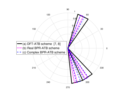
Particularly, the phase rotation on the transmitted signals is effectively equivalent to rotating the phases of the corresponding channel coefficients. It should be noted that, the conventional DFT-ATB scheme generates a satisfactory array gain with equivalent channel [8401880, 6928432], but this scheme suffers a phase angle optimization problem, which leads to a wide beamspace of the equivalent channel as shown in Fig. 1. Using by (6) and [8401880], the optimization problem can be formulated

𝐟2qopt=argmax𝐟2qRs.t.𝐟2q{,0}2q,and||𝐟2q||0=2q1,fragments𝐟fragments2𝑞fragmentsoptfragmentsargmaxfragmentsffragments2𝑞𝑅𝑠.𝑡.𝐟fragments2𝑞{,0}fragments2𝑞,and||𝐟fragments2𝑞||02fragmentsq1,\begin{split}\mathbf{f}_{2^{q}}^{opt}&=\operatorname*{arg\,max}_{\mathbf{f}_{2^{q}}}R\\ &s.t.\hskip 3.0pt\mathbf{f}_{2^{q}}\in\left\{\mathcal{F},0\right\}^{2^{q}},\\ &\textrm{and}\hskip 5.0pt||\mathbf{f}_{2^{q}}||_{0}=2^{q-1},\end{split} (7)

where 𝐟2qfragmentsffragments2𝑞\mathbf{f}_{2^{q}} denotes the vector of 𝐅2qfragmentsFfragments2𝑞\mathbf{F}_{2^{q}}. We observe that the (7) maximizes the spectral efficiency but it has a non-convex objective function, which conducts a phase angle optimization problem. In addition, the spectral efficiency (6) is a correctly monotone enhancing function of beamforming gain |𝐡𝐟2q|fragments|hffragments2𝑞||\mathbf{h}\mathbf{f}_{2^{q}}|. To simplify this problem, we formulate the phase angle optimization as below:

Let hνfragmentsh𝜈h_{\nu} be the ν𝜈\nu-th element of 𝐡𝐡\mathbf{h} and 𝐟2q,νfragmentsffragments2𝑞,νF\mathbf{f}_{2^{q},\nu}\in\mathcal{F} be the effective analog beamforming vector. Thus, the phase angle optimization problem is given by

φνopt=argmaxφν|ν=12qhν𝐟2q,ν(φν)|s.t.φν{2πb2q|b=0,1,2q1},andν=1,,2q,fragments𝜑𝜈fragmentsoptfragmentsargmaxfragmentsφ𝜈|fragmentsν1fragments2𝑞𝜈𝐟fragments2𝑞,ν(𝜑𝜈)|𝑠.𝑡.𝜑𝜈{fragments2πbfragments2𝑞|𝑏0,1,2𝑞1},and𝜈1,,2𝑞,\begin{split}\varphi_{\nu}^{opt}&=\operatorname*{arg\,max}_{\varphi_{\nu}}\left|\sum_{\nu=1}^{2^{q}}h_{\nu}^{*}\mathbf{f}_{2^{q},\nu}(\varphi_{\nu})\right|\\ &s.t.\hskip 3.0pt\varphi_{\nu}\in\left\{\frac{2\pi b}{2^{q}}\bigg{|}b=0,1...,2^{q}-1\right\},\\ &\textrm{and}\hskip 5.0pt\nu=1,...,2^{q},\end{split} (8)

where 𝐟ν(φν)=ejφν/2qfragmentsf𝜈(φ𝜈)efragmentsjφ𝜈fragments2𝑞\mathbf{f}_{\nu}(\varphi_{\nu})=e^{j\varphi_{\nu}}/\sqrt{2^{q}}. We observe the (8) is still leading an optimization problem due to the global phase angle, which generates an extensive beamspsce with a mmWave channel. As a result, the user suffers from a high computational burden to optimize the global phase angle. To overcome the phase angle optimization problem, we reformulate (8) and propose the BPR-ATB based algorithm in the Subsection C.

III-C Proposed BPR-ATB based algorithm

Let φν{ϕν1,ϕν2}fragmentsφ𝜈{ϕfragmentsν1,ϕfragmentsν2}\varphi_{\nu}\in\{{\phi_{\nu_{1}},\phi_{\nu_{2}}}\}, where ϕν1fragmentsϕfragmentsν1\phi_{\nu_{1}} and ϕν2fragmentsϕfragmentsν2\phi_{\nu_{2}} are the block phase angle of 𝐀2q1fragmentsAfragments2fragmentsq1\mathbf{A}_{2^{q-1}} and 𝐁2q1fragmentsBfragments2fragmentsq1\mathbf{B}_{2^{q-1}}. We set ϕν1fragmentsϕfragmentsν1\phi_{\nu_{1}} and ϕν2fragmentsϕfragmentsν2\phi_{\nu_{2}} in the designed transmit beamformer of 𝐅2qfragmentsFfragments2𝑞\mathbf{F}_{2^{q}}. Then the optimal block phase angle is given by

φν(ϕν1opt,ϕν2opt)=argmaxϕν1,ϕν2|ν=12qhνejϕν1ejϕν2|s.t.ϕν1{2πb12q1|b1=0,1,2q11},ϕν2{2πb22q1|b2=2q1,2q1},ν1=ν2andb1b2.fragments𝜑𝜈(italic-ϕfragmentsν1fragmentsopt,italic-ϕfragmentsν2fragmentsopt)fragmentsargmaxfragmentsϕfragmentsν1,ϕfragmentsν2|fragmentsν1fragments2𝑞𝜈𝑒fragmentsjϕfragmentsν1𝑒fragmentsjϕfragmentsν2|𝑠.𝑡.italic-ϕfragmentsν1{fragments2πb1fragments2fragmentsq1|𝑏10,1,2fragmentsq11},italic-ϕfragmentsν2{fragments2πb2fragments2fragmentsq1|𝑏22fragmentsq1,2𝑞1},𝜈1𝜈2and𝑏1𝑏2.\begin{split}\varphi_{\nu}(\phi_{\nu_{1}}^{opt},\phi_{\nu_{2}}^{opt})&=\operatorname*{arg\,max}_{\phi_{\nu_{1}},\phi_{\nu_{2}}}\left|\sum_{\nu=1}^{2^{q}}h_{\nu}^{*}e^{j\phi_{\nu_{1}}}e^{j\phi_{\nu_{2}}}\right|\\ &s.t.\hskip 3.0pt\phi_{\nu_{1}}\in\left\{\frac{2\pi b_{1}}{2^{q-1}}\bigg{|}b_{1}=0,1...,2^{q-1}-1\right\},\\ &\hskip 3.0pt\phi_{\nu_{2}}\in\left\{\frac{2\pi b_{2}}{2^{q-1}}\bigg{|}b_{2}=2^{q-1}...,2^{q}-1\right\},\\ &\nu_{1}=\nu_{2}\hskip 5.0pt\textrm{and}\hskip 5.0ptb_{1}\neq b_{2}.\end{split} (9)
Algorithm 1 Proposed BPR-ATB based Algorithm
1: Input parameters: 𝐡𝐡\mathbf{h}, b1fragmentsb1b_{1}, b2fragmentsb2b_{2} q𝑞q.
2:Output: 𝐟2q,voptfragmentsffragments2𝑞,vfragmentsopt\mathbf{f}_{2^{q},v}^{opt}.
3:Obtain φν(ϕν1opt,ϕν2opt)fragmentsφ𝜈(ϕfragmentsν1fragmentsopt,ϕfragmentsν2fragmentsopt)\varphi_{\nu}(\phi_{\nu_{1}}^{opt},\phi_{\nu_{2}}^{opt}) .
4:Begin 𝒞:={ν}fragmentsCassign{ν}\mathcal{C}:=\{\nu\}, ν{𝒮ν1,𝒮ν2}fragmentsν{Sfragmentsν1,Sfragmentsν2}\nu\in\{\mathcal{S}_{\nu_{1}},\mathcal{S}_{\nu_{2}}\}, and 𝒮ν1=𝒮ν2=fragmentsSfragmentsν1Sfragmentsν2\mathcal{S}_{\nu_{1}}=\mathcal{S}_{\nu_{2}}=\emptyset.
5:for ν1=1:2q1fragmentsν11:2fragmentsq1\nu_{1}=1:2^{q-1} do
6:Find νopt1=argmaxν𝒞|ν1𝒮ν1(hν1+hνejϕν2)ejϕν1|fragmentsνfragmentsopt1fragmentsargmaxfragmentsνC|fragmentsν1Sfragmentsν1(hfragmentsν1h𝜈efragmentsjϕfragmentsν2)efragmentsjϕfragmentsν1|{\nu}^{opt_{1}}=\operatorname*{arg\,max}_{\nu\in{\mathcal{C}}}\left|\sum_{\nu_{1}\in\mathcal{S}_{\nu_{1}}}(h_{\nu_{1}}^{*}+h_{\nu}^{*}e^{j\phi_{\nu_{2}}})e^{j\phi_{\nu_{1}}}\right|.
7:𝒮ν1fragmentsSfragmentsν1\mathcal{S}_{\nu_{1}} :=𝒮ν1{νopt1}fragmentsassignSfragmentsν1{νfragmentsopt1}:=\mathcal{S}_{\nu_{1}}\bigcup{\{\nu}^{opt_{1}}\}.
8:𝒞𝒞\mathcal{C} :=𝒞mod{νopt1}fragmentsassignCmod{νfragmentsopt1}:=\mathcal{C}\hskip 2.0pt\text{mod}\hskip 2.0pt\{{\nu}^{opt_{1}}\}.
9:end for
10:for ν2=1:2q1fragmentsν21:2fragmentsq1\nu_{2}=1:2^{q-1} do
11:Find νopt2=argmaxν𝒞|ν2𝒮ν2(hν2+hνejϕν1)ejϕν2|fragmentsνfragmentsopt2fragmentsargmaxfragmentsνC|fragmentsν2Sfragmentsν2(hfragmentsν2h𝜈efragmentsjϕfragmentsν1)efragmentsjϕfragmentsν2|{\nu}^{opt_{2}}=\operatorname*{arg\,max}_{\nu\in{\mathcal{C}}}\left|\sum_{\nu_{2}\in\mathcal{S}_{\nu_{2}}}(h_{\nu_{2}}^{*}+h_{\nu}^{*}e^{j\phi_{\nu_{1}}})e^{j\phi_{\nu_{2}}}\right|.
12:𝒮ν2fragmentsSfragmentsν2\mathcal{S}_{\nu_{2}} :=𝒮ν2{νopt2}fragmentsassignSfragmentsν2{νfragmentsopt2}:=\mathcal{S}_{\nu_{2}}\bigcup{\{\nu}^{opt_{2}}\}.
13:𝒞𝒞\mathcal{C} :=𝒞mod{νopt2}fragmentsassignCmod{νfragmentsopt2}:=\mathcal{C}\hskip 2.0pt\text{mod}\hskip 2.0pt\{{\nu}^{opt_{2}}\}.
14:end for
15:Obtain 𝐟2q,vopt=(gejϕν1optejϕν2opt)/ζfragmentsffragments2𝑞,vfragmentsopt(gefragmentsjϕfragmentsν1fragmentsoptefragmentsjϕfragmentsν2fragmentsopt)𝜁\mathbf{f}_{2^{q},v}^{opt}=(ge^{j\phi_{\nu_{1}}^{opt}}e^{j\phi_{\nu_{2}}^{opt}})/{\sqrt{\zeta}} according to (9).

Consider 𝒞𝒞\mathcal{C} as the set of indexes of useful antennas and ν{𝒮ν1,𝒮ν2}fragmentsν{Sfragmentsν1,Sfragmentsν2}\nu\in\{\mathcal{S}_{\nu_{1}},\mathcal{S}_{\nu_{2}}\}, where 𝒮ν1fragmentsSfragmentsν1\mathcal{S}_{\nu_{1}} and 𝒮ν2fragmentsSfragmentsν2\mathcal{S}_{\nu_{2}} are the subset of beam indices. Based on (9), we demonstrate the proposed BPR-ATB scheme in Algorithm 1.

IV Simulation Results and Discussion

In this section, we compare the proposed BPR-ATB scheme against the conventional DFT-ATB scheme via computer simulations. To show the superiority of the proposed scheme, we employ a complex Alamouti coding technique at the transmitter. For example, if we use the k𝑘k-th entry of a complex alamouti code with time slot T=2fragmentsT2T=2 in (4) where we consider T𝑇T is equal to the number of radio frequency chain, then the codeword matrix 𝐗𝐗\mathbf{X} is given by whereS_kisthek-then

Conversion to HTML had a Fatal error and exited abruptly. This document may be truncated or damaged.