Nematic and smectic stripe phases and stripe-SkX transformations
Abstract
Based on the findings of skyrmion nature of stripes and the metastability of a
state of an arbitrary number of skyrmions, precisely controlled manipulation of
stripes of skyrmion number 1 in pre-designed structures and mutual transformation
between helical states and skyrmion crystals (SkXs) are demonstrated in chiral
magnetic films. As a proof of the concept, we show how to use patterned magnetic
fields and spin-transfer torques (STTs) to generate nematic and smectic stripe
phases, as well as “UST” mosaic from three curved stripes. Cutting one stripe
into many pieces and coalescing several skyrmions into one by various external
fields are good ways to transform helical states and SkXs from each other.
Spintronic, Landau–Lifshitz–Gilbert Equation Simulation,
Stripe Skyrmion, Skyrmion Crystal, Nematic Phase.
75.50.Gg 75.70.Ak 75.60.Ch
1. Introduction
Magnetic skyrmions, topologically non-trivial spin textures characterized by skyrmion number , provide a fertile ground for studying fundamental physics such as the topological Hall effect that is a phenomenon about how non-collinear spins in skyrmion crystals (SkXs) affect electron transport [1, 2, 3]. Here is the unit vector of the magnetization. Skyrmions were observed in systems involving Dzyaloshinskii–Moriya interaction (DMI) [4, 5, 6, 7, 8, 9] or geometric frustration [10, 11, 12]. Skyrmions are commonly believed to disk-like objects, and three families of circular skyrmions have been identified, namely spiral (Bloch type) skyrmions, hedgehog (Néel type) skyrmions, and anti-skyrmions [1, 4, 8, 9]. Recently, it is shown that irregular stripes and maze structures are also skyrmions with topological skyrmion number 1 [13]. With this expanded zoo, skyrmions provide a useful platform for studying fundamental sciences, other than potential applications in information technology. For example, one can study the interplay of topology, shape, spin and charge. One can ask how topologically non-trivial textures in various forms affect electron transport if a precise control of condensed skyrmion states is possible? Creation and control of topologically non-trivial stripes in long-term searching [1] nematic and smectic phases with pre-designed elongation and orientation are the main theme of current study.
Many efforts have been made in skyrmion generations, manipulations, and detections [14, 15, 16, 17, 18, 19, 20, 21, 22, 23, 24, 25, 26, 27, 28, 29, 30, 31, 32, 33, 34, 3, 35, 36, 37, 38, 7, 39, 40, 41, 42, 43, 44, 45, 46, 47, 48]. Magnetic fields [14, 15, 16, 17, 18, 19, 20, 21, 22], electric fields [23, 24, 25, 26, 27, 28, 29, 30, 31, 32, 33, 34, 21], currents [3, 35, 36, 37, 38, 7, 39, 40], geometric constrains [41, 42, 43], spin waves [44, 45, 46] and temperature gradient [16, 17] were used to generate and manipulate skyrmions. There were also demonstrations of how to use STM to add and delete a skyrmion in skyrmion crystals (SkXs) [7]. With all the advances made to date in skyrmion manipulation, the control of helical states and SkXs often relies on the luck and a hunch. It is a formidable task to control the shape and morphology of individual stripes and the overall arrangement of a group of them. This is why the long-time suspected liquid-crystal-like skyrmion phases such as nematic or smectic configurations have not been found yet [1]. It is also not clear how to precisely control transitions from helical states to SkXs. The lack of the ability in stripe control is largely due to our ignorance about the skyrmionic nature of stripes and the origin of complicated stripe morphologies that include dendrite-like and maze structures. Our recent discovery of the skyrmion nature of stripes and sensitivity of stripe morphology to skyrmion number density [13, 49] provides new thoughts about stripe-state-control and possible control of transformations between helical states to SkXs at nanometer scale.
In this paper, how to use patterned spin-transfer torques (STTs) to create a
long-term searching nematic and smectic stripe phase is demonstrated.
The lengths and orientations of stripes can be controlled by the skyrmion
density and arrangement using patterned fields and STTs. Each stripe has a
skyrmion number 1. The smectic stripe phase becomes an SkX when the stripe
length is order of the stripe width. It is also possible to transform an SkX
to a smectic or a nematic phase by using field pulses to coalesce skyrmions.
It is even possible to construct a symbol of “UST” with three curved
topologically non-trivial stripes.
2. Model and methods
We consider a thin chiral magnetic film of thickness in the plane. Its magnetic energy reads
| (1) |
where , , , , , and are the Heisenberg exchange stiffness, the DMI coefficient, the perpendicular magneto-crystalline anisotropy, the vacuum permeability, the saturation magnetization, the external magnetic field, and the dipolar field, respectively. is chosen for state of . In the analytical considerations, the static magnetic interaction for a thin film can be included through the effective magnetic anisotropy constant (dipolar interaction is fully included in all of our MuMax3 simulations [50]). This theoretical approximation is good when the film thickness is much smaller than the exchange length [51, 52].
Magnetization unit vector is govern by the Landau-Lifshitz-Gilbert (LLG) equation
| (2) |
where and are respectively the gyromagnetic ratio and the Gilbert damping constant. is the effective field including the exchange field, the magneto-crystalline anisotropy field, the DMI field , the external magnetic field H, and the magnetic dipolar field . is STTs due to spin polarized electric current or spin current of polarization [53], where proportional to charge current density describes out-of-plane torque, and is a dimensionless parameter characterizing the in-plane torque. In this study, is assumed if not stated otherwise. Eq. 2 is numerically solved by Mumax3 package [50] for various patterned currents and magnetic fields. It should be pointed out that MuMax3 [50] includes properly the demagnetization field and considers both open or periodic boundary conditions. The results in this work are for the open boundary conditions (See the Supporting Information). Mesh size in this study is . A large is used to speed up stable spin structure search. does not affect the properties of stable and metastable states. Skyrmion number of a given spin texture is calculated according to its definition, which can be extracted directly from MuMax3 [50]. The material parameters are , (), , and (See the Supporting Information), unless otherwise stated.
3. Principles of stripe-state-control
One of the breakthroughs in skyrmion physics is the understanding of skyrmion
nature of all kinds of stripes, long and short, curved and straight, ramified and
non-ramified, in helical, spiral, conical states and in dendrite-like and maze
structures. Stripes are the natural form of skyrmions when , and the ground state is a condensed skyrmion phase with skyrmions
occupying the whole chiral magnetic film, in contrast to isolated circular
skyrmions that are metastable in a film with
[13, 51]. The film with an arbitrary number of skyrmions
is metastable [13, 49]. This is very similar
to a BEC condensate with many atoms staying together (in one energy state).
These stripes, attempting to fill up the whole system, have a well-defined
width of with for
[13, 49]. These new understandings are supported by the
observation of topological charges in stripe structures [54, 55] and continuous deformation between circular skyrmions and stripes
[56, 57, 58, 59]. No fundamental difference
between these skyrmions of different shapes is a putative conclusion of the new
understanding, and transformation from one into another is therefore highly
possible if a proper kinetic path is used. The final stripe morphology depends on
skyrmion number density, the initial configuration, and the actual spin dynamics.
These multiple effects explain the rich morphologies and structures of the
condensed skyrmion phases. This new understanding of the condensed skyrmion
phases provides a new methodology of creating and manipulating ordered stripe
structures by using proper external forces, such as patterned fields and spin
torques, to control the initial skyrmion seeds and their locations, as well as
spin dynamics.
4. Arbitrary skyrmion structures
As a proof of the concept, a chiral magnetic film with parameters given in Model and Methods is considered. This film has such that its ground state is stripe skyrmions [13, 49]. It is convenient to use a coordinate system with the origin at the left bottom corner such that the film is in nmnm, nmnm. In this study, the initial state is a perpendicular ferromagnetic state of with the help of a strong magnetic field of .
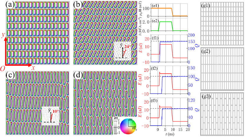
At , a patterned STT pulse of ns long is used to create different ordered nucleation domains of in the ferromagnetic background. The STT increases linearly from 0 to its full value of s-1, corresponding to an electric current density of A cm-2, in ns and linearly decreases later to zero from ns to ns as shown in Fig. 1(e2). is linearly switched off from ns to ns as shown in Fig. 1(e1). Figure 1(a) shows 153 stripes of nm wide and nm long in a stable/metastable smectic phase at ns after the STT pulse is applied to 153 rectangular areas of with nm and nm. The corresponding STT pattern is shown by white rectangulars in Fig. 1(g1), where an STT torque of s-1 is applied. The STT pulse reverses some spins in these areas that evolve into well-aligned stripes. The process is captured by the evolutions of system energy and skyrmion number as shown in Fig. 1(f1). Under the STT and , the system quickly reaches the stable smectic phase represented by constant and . Figure 1(b) is the stable smectic stripe phase at ns in the absence of the magnetic field and the STT. Stripes tilt an angle of from the axis (the Inset). The whole process from Fig. 1(a) to Fig. 1(b) is captured in the first part of Video 1. A smectic phase can also be obtained in a bulk sample by the same method where each stripe is replaced by a stripe tube that can be viewed as stacked stripes, similar to the skyrmion strings in the literature (see the Supporting Information).
The length of stripes can be controlled by varying the length of rectangles where STT is applied. Figure 1(c) is the stable/metastable smectic stripe phase in the absence of the field and the STT, after the STT pulse Fig. 1(e2) is applied on 100 rectangular areas of with nm and nm. Stripe skyrmions are 162 nm long, longer than those in Fig. 1(a) and Fig. 1(b). The corresponding STT pattern is shown in Fig. 1(g2). Stripes are inclined away from the vertical direction for very simple physics: The stripe width is fixed [13, 51] while their length is stretchable in order to lower their energy due to the negative formation energy of skyrmions. For parallel aligned stripes of along , stripes will incline away from the vertical direction if . The titled angle satisfies . For stripes in Fig. 1(b), , nm, nm such that . For stripes in Fig. 1(c), , nm, nm such that , which are very close to the observed values.
In order to create a nematic phase with 80 stripes, we apply a field pulse of Fig. 1(e1) and a patterned STT pulse of Fig. 1(e2) on 80 rectangular areas: for odd , and for even , , nm and nm. A stable nematic stripe phase is obtained in the absence of the field and the STT as shown in Fig. 1(d). The corresponding STT pattern is shown in Fig. 1(g3). Skyrmion number , as well as stripe number, in two smectic phases [Fig. 1(b) and Fig. 1(c)] and the nematic phase [Fig. 1(d)] are 153, 100, and 80, respectively. This supports the claim that all stripes have skyrmion number 1. The widths of all stripes in these figures are the same about nm, smaller than the stripe width in the presence of the field and the STT that prefers wider skyrmions as shown in Fig. 1(a).
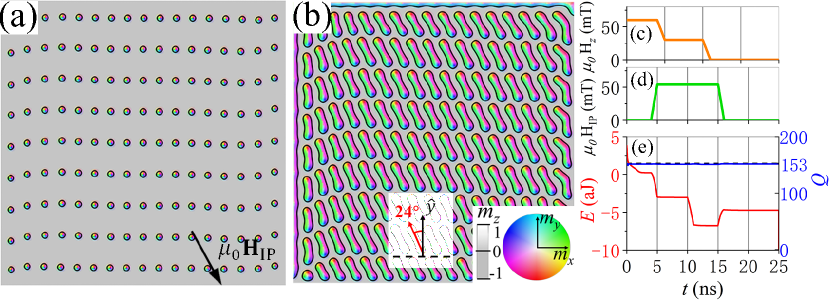
It is also possible to transform one stripe phase into another by using external forces. For example, starting from the stable smectic phase in Fig. 1(b) where stripes align north-east, stripes shrink into disks as shown in Fig. 2(a), ns after a field pulse shown in Fig. 2(c) is applied at . Each disk is a circular skyrmion of skyrmion number 1 as shown in Fig. 2(e) where skyrmion number and energy does not change with time. At ns, is linearly switched off and an in-plane field pulse of mT strong and ns long, pointing south-east indicated by the arrow in Fig. 2(a), is switched on at the same time. The time dependence of two field pulses are given in Fig. 2(c) and Fig. 2(d), respectively. A new stable smectic phase where stripes align north-west as shown in Fig. 2(b) is obtained after the removal of external fields. The transformation between two smectic phases is recorded in the second part of Video 1.
Since condensed skyrmions prefer an SkX structure when the skyrmion-skyrmion distance is comparable to the stripe width, an SkX can also be obtained from a ferromagnetic state of by creating a denser skyrmion nucleation centers with using the same field and STT pulses described in Fig. 1(e1-e2). This can be achieved by applying the STT pulses on 340 rectangular areas of with nm and nm. Figure 3(a) shows the stable SkX at ns in the absence of both fields and STTs. Inset of Fig. 3(a) shows the corresponding STT pattern.
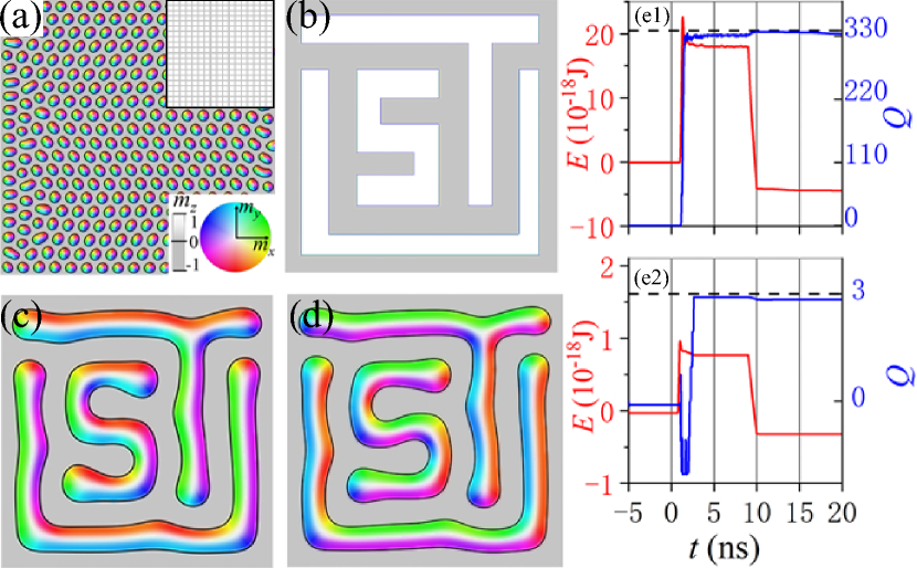
It is even possible to use stripes to create other more exotic patterns like “UST” mosaic, as long as two neighbouring stripes have a distance around their natural width. As shown in Fig. 3(b), a “UST” mask is designed in a film that has the same material parameters as those in Fig. 1 and 2. The film is initially in the ferromagnetic state of under the field pulse shown in Fig. 1(e1). At , the STT pulse of Fig. 1(e2) is applied on the mask of Fig. 3(b), and Fig. 3(c) is the final stable pattern ns after both the magnetic field and the STT are switched off. This process is recorded in Video 2. To substantiate our claim that both SkX and “UST” mosaic are stable spin structures, Fig. 3(e1,e2) plot the time evolution of energy (the red and the left axis) and skyrmion number (the blue and the right axis) for SkX and “UST” mosaic systems. Clearly, both and become constants shortly after ns. Furthermore, it is interesting to notice that “UST” mosaic is made from three stripes, each one of which has skyrmion number 1 and is in shape of “U”, “S”, and “T”, respectively.
Only interfacial DMI is considered so far, but the results are essentially
the same in a film with bulk DMI. If the interfacial DMI in Eq. 1 is replaced by
the bulk-type DMI of , using
exactly the same mask of Fig. 3(b) and the same field and STT pulses
of Fig. 1(e1-e2), similar “UST” mosaic is obtained as shown in
Fig. 3(d). The only difference is that the Neel-type stripes in the
interfacial DMI become Bloch-type stripes in a film with bulk DMI
[13].
5. Structure transformations
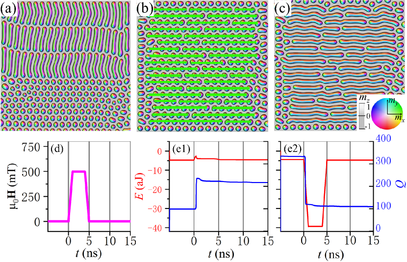
Cutting stripes into smaller pieces is a good way to transform helical states into SkXs. This method is beyond thermodynamic process and can directly drive a system from one metastable state into another one. Using the smectic phase of Fig. 1(c) as an example, a field pulse of mT strong and ns long is applied in 8 rectangular areas of with nm. The field pulse, whose shape is shown in Fig. 4(d), cuts the two lower rows of stripes in Fig. 1(c) into 8 evenly spacing smaller pieces that become circular skyrmions and are in a lattice structure. Figure 4(a) shows coexistence of a smectic stripe phase and an SkX at ns. Figure 4(e1) shows how the energy (the red and the left axis) and the skyrmion number (the blue and the right axis) vary with time after the field pulse.
It is also possible to transfer an SkX into a nematic phase by coalescing
many skyrmions into one. As exemplified in the SkX of Fig. 3(a), a
strong magnetic field along the -direction can coalesce skyrmions.
Figure 4(c) shows the final stable nematic stripe phase after a
field pulse of the same shape illustrated in Fig. 4(d) (but along
the -direction) is applied to a patterned film that consists of 42
rectangles of nm wide and various lengths indicated by the green color in
Fig. 4(b). The field pulse coalesces circular skyrmions into stripe
skyrmions, and transforms an SkX into a nematic stripe phase. As shown in
Fig. 4(e2), the nematic phase is a stable spin structure of the system
since both energy and skyrmion number do not vary with time ns
after external stimulus is switched off. The film, starting with more than
300 circular skyrmions before the magnetic field pulse, consists of 42 stripes
and a number of disk-like skyrmions after the field pulse.
6. Discussion and conclusion
All structures we obtained are stable/metastable against thermal agitation. To substantiate this assertion, we performed MuMax3 simulations at a finite temperature [50, 60]. Video 3 shows the stability of smectic phase of Fig. 1(b) at K ( is around K) in the absence of fields and STTs. Stripe skyrmions keep their shape and arrangements unchanged under thermal agitation (see the Supporting Information). Actually, as far as the temperature is not too close to , metastable spin textures keep unchanged for a long time [49].
Although only magnetic fields and STTs are used here to generate different spin structures and to induce transformations from one ordered skyrmion structure into another one, other external forces, such as spin-orbit torques, are equally good as long as they can induce magnetization reversal such that nucleation domains can be created to generate skyrmions.
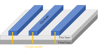
One important issue is the feasibility of approaches studied here. Firstly, insulating and superconducting masks of nano-meter scale should not be a problem for today’s technology. In terms of patterned fields or STTs, one may put masks on both sides of the film using either insulating materials or superconducting materials to shield either fields or electric currents such that one can realize the desired STT or field patterns. For example, one can use standard magnetic tunnelling junction (MTJ) with a ferromagnetic fixed layer for STT generation and a chiral magnetic free-layer sandwiching a spacing layer. A patterned STT will be generated if a tunnelling current passes through the structure. It should not be hard to fabricate structures or masks such as the one shown in Fig. 5 at nanometer scale with state-of-art photolithography technologies. Also, masks for generating those patterned STTs and fields shown in the Figs. 1-4 should be also an easy task with using existing nano-fabrication facilities such as all kinds of lithography technologies, ion beam, and all kinds of etching methods.
Apart from generating the long-term searching nematic/smectic phase, one potential application of our result is neuromorphic computing. Stripes may work as non-volatile synapse encoding the synapse connections by stripe shapes and orientations through the tunnelling magnetoresistance or Hall resistance. One attraction of stripe synapses is the controllability by stimulus, such as fields and spin torques. Stripe-based neuromorphic devices shall be more robust than isolated skyrmions-based devices, because of the higher energy barrier and entanglements.
In summary, how to use patterned magnetic field and STT pulses to create various ordered stripe phases is demonstrated. Based on the stripe nature of skyrmions in the ground state of a chiral magnetic film that can host an arbitrary number of skyrmions, the creation of long-term searching nematic and smectic stripe phases is demonstrated. Cutting long stripes into shorter pieces or coalescing many small skyrmions into one stripe skyrmion is a useful way to transform various stripe structures from each other and into SkXs, and vice versa. It is also demonstrated how to create curved stripes that form a “UST” mosaic. These findings provide a guidance to skyrmion manipulations.
References
- Back et al. [2020] C. Back, V. Cros, H. Ebert, K. Everschor-Sitte, A. Fert, M. Garst, T. Ma, S. Mankovsky, T. L. Monchesky, M. Mostovoy, N. Nagaosa, S. S. P. Parkin, C. Pfleiderer, N. Reyren, A. Rosch, Y. Taguchi, Y. Tokura, K. von Bergmann, and J. Zang, Journal of Physics D: Applied Physics 53, 363001 (2020).
- Neubauer et al. [2009] A. Neubauer, C. Pfleiderer, B. Binz, A. Rosch, R. Ritz, P. G. Niklowitz, and P. Böni, Phys. Rev. Lett. 102, 186602 (2009).
- Zang et al. [2011] J. Zang, M. Mostovoy, J. H. Han, and N. Nagaosa, Phys. Rev. Lett. 107, 136804 (2011).
- Yu et al. [2010] X. Z. Yu, Y. Onose, N. Kanazawa, J. H. Park, J. H. Han, Y. Matsui, N. Nagaosa, and Y. Tokura, Nature 465, 901 (2010).
- Mühlbauer et al. [2009] S. Mühlbauer, B. Binz, F. Jonietz, C. Pfleiderer, A. Rosch, A. Neubauer, R. Georgii, and P. Böni, Science 323, 915 (2009).
- Heinze et al. [2011] S. Heinze, K. von Bergmann, M. Menzel, J. Brede, A. Kubetzka, R. Wiesendanger, G. Bihlmayer, and S. Blügel, Nature Physics 7, 713 (2011).
- Romming et al. [2013] N. Romming, C. Hanneken, M. Menzel, J. E. Bickel, B. Wolter, K. von Bergmann, A. Kubetzka, and R. Wiesendanger, Science 341, 636 (2013).
- Kézsmárki et al. [2015] I. Kézsmárki, S. Bordács, P. Milde, E. Neuber, L. M. Eng, J. S. White, H. M. Rønnow, C. D. Dewhurst, M. Mochizuki, K. Yanai, H. Nakamura, D. Ehlers, V. Tsurkan, and A. Loidl, Nature Materials 14, 1116 (2015).
- Nayak et al. [2017] A. K. Nayak, V. Kumar, T. Ma, P. Werner, E. Pippel, R. Sahoo, F. Damay, U. K. Rößler, C. Felser, and S. S. P. Parkin, Nature 548, 561 (2017).
- Okubo et al. [2012] T. Okubo, S. Chung, and H. Kawamura, Phys. Rev. Lett. 108, 017206 (2012).
- Leonov and Mostovoy [2015] A. O. Leonov and M. Mostovoy, Nature Communications 6, 8275 (2015).
- Kurumaji et al. [2019] T. Kurumaji, T. Nakajima, M. Hirschberger, A. Kikkawa, Y. Yamasaki, H. Sagayama, H. Nakao, Y. Taguchi, T. hisa Arima, and Y. Tokura, Science 365, 914 (2019).
- Wang et al. [2021] X. R. Wang, X. C. Hu, and H. T. Wu, Communications Physics 4, 142 (2021).
- Flovik et al. [2017] V. Flovik, A. Qaiumzadeh, A. K. Nandy, C. Heo, and T. Rasing, Phys. Rev. B 96, 140411 (2017).
- Müller et al. [2016] J. Müller, A. Rosch, and M. Garst, New Journal of Physics 18, 065006 (2016).
- Kong and Zang [2013] L. Kong and J. Zang, Phys. Rev. Lett. 111, 067203 (2013).
- Wang et al. [2020] Z. Wang, M. Guo, H.-A. Zhou, L. Zhao, T. Xu, R. Tomasello, H. Bai, Y. Dong, S.-G. Je, W. Chao, H.-S. Han, S. Lee, K.-S. Lee, Y. Yao, W. Han, C. Song, H. Wu, M. Carpentieri, G. Finocchio, M.-Y. Im, S.-Z. Lin, and W. Jiang, Nature Electronics 3, 672 (2020).
- Jonietz et al. [2010] F. Jonietz, S. Mühlbauer, C. Pfleiderer, A. Neubauer, W. Münzer, A. Bauer, T. Adams, R. Georgii, P. Böni, R. A. Duine, K. Everschor, M. Garst, and A. Rosch, Science 330, 1648 (2010).
- Wang et al. [2015] W. Wang, M. Beg, B. Zhang, W. Kuch, and H. Fangohr, Phys. Rev. B 92, 020403 (2015).
- Wang et al. [2017] C. Wang, D. Xiao, X. Chen, Y. Zhou, and Y. Liu, New Journal of Physics 19, 083008 (2017).
- Yuan et al. [2019] H. Y. Yuan, X. S. Wang, M.-H. Yung, and X. R. Wang, Phys. Rev. B 99, 014428 (2019).
- White et al. [2014] J. S. White, K. Prša, P. Huang, A. A. Omrani, I. Živković, M. Bartkowiak, H. Berger, A. Magrez, J. L. Gavilano, G. Nagy, J. Zang, and H. M. Rønnow, Phys. Rev. Lett. 113, 107203 (2014).
- Chiba et al. [2008] D. Chiba, M. Sawicki, Y. Nishitani, Y. Nakatani, F. Matsukura, and H. Ohno, Nature 455, 515 (2008).
- Ohno et al. [2000] H. Ohno, D. Chiba, F. Matsukura, T. Omiya, E. Abe, T. Dietl, Y. Ohno, and K. Ohtani, Nature 408, 944 (2000).
- Ando et al. [2016] F. Ando, H. Kakizakai, T. Koyama, K. Yamada, M. Kawaguchi, S. Kim, K.-J. Kim, T. Moriyama, D. Chiba, and T. Ono, Applied Physics Letters 109, 022401 (2016).
- Dohi et al. [2016] T. Dohi, S. Kanai, A. Okada, F. Matsukura, and H. Ohno, AIP Advances 6, 075017 (2016).
- Weisheit et al. [2007] M. Weisheit, S. Fähler, A. Marty, Y. Souche, C. Poinsignon, and D. Givord, Science 315, 349 (2007).
- Maruyama et al. [2009] T. Maruyama, Y. Shiota, T. Nozaki, K. Ohta, N. Toda, M. Mizuguchi, A. A. Tulapurkar, T. Shinjo, M. Shiraishi, S. Mizukami, Y. Ando, and Y. Suzuki, Nature Nanotechnology 4, 158 (2009).
- Lebeugle et al. [2009] D. Lebeugle, A. Mougin, M. Viret, D. Colson, and L. Ranno, Phys. Rev. Lett. 103, 257601 (2009).
- Yang et al. [2018] H. Yang, O. Boulle, V. Cros, A. Fert, and M. Chshiev, Scientific Reports 8, 12356 (2018).
- Heron et al. [2011] J. T. Heron, M. Trassin, K. Ashraf, M. Gajek, Q. He, S. Y. Yang, D. E. Nikonov, Y.-H. Chu, S. Salahuddin, and R. Ramesh, Phys. Rev. Lett. 107, 217202 (2011).
- Schellekens et al. [2012] A. J. Schellekens, A. van den Brink, J. H. Franken, H. J. M. Swagten, and B. Koopmans, Nature Communications 3, 847 (2012).
- Chiba et al. [2012] D. Chiba, M. Kawaguchi, S. Fukami, N. Ishiwata, K. Shimamura, K. Kobayashi, and T. Ono, Nature Communications 3, 888 (2012).
- Franke et al. [2015] K. J. A. Franke, B. Van de Wiele, Y. Shirahata, S. J. Hämäläinen, T. Taniyama, and S. van Dijken, Phys. Rev. X 5, 011010 (2015).
- Woo et al. [2016] S. Woo, K. Litzius, B. Krüger, M.-Y. Im, L. Caretta, K. Richter, M. Mann, A. Krone, R. M. Reeve, M. Weigand, P. Agrawal, I. Lemesh, M.-A. Mawass, P. Fischer, M. Kläui, and G. S. D. Beach, Nature Materials 15, 501 (2016).
- Schulz et al. [2012] T. Schulz, R. Ritz, A. Bauer, M. Halder, M. Wagner, C. Franz, C. Pfleiderer, K. Everschor, M. Garst, and A. Rosch, Nature Physics 8, 301 (2012).
- Gong et al. [2020] X. Gong, H. Y. Yuan, and X. R. Wang, Phys. Rev. B 101, 064421 (2020).
- Yuan and Wang [2016] H. Y. Yuan and X. R. Wang, Scientific Reports 6, 22638 (2016).
- Sampaio et al. [2013] J. Sampaio, V. Cros, S. Rohart, A. Thiaville, and A. Fert, Nature Nanotechnology 8, 839 (2013).
- Dürrenfeld et al. [2017] P. Dürrenfeld, Y. Xu, J. Åkerman, and Y. Zhou, Phys. Rev. B 96, 054430 (2017).
- Li et al. [2014] J. Li, A. Tan, K. W. Moon, A. Doran, M. A. Marcus, A. T. Young, E. Arenholz, S. Ma, R. F. Yang, C. Hwang, and Z. Q. Qiu, Nature Communications 5, 4704 (2014).
- Jiang et al. [2015] W. Jiang, P. Upadhyaya, W. Zhang, G. Yu, M. B. Jungfleisch, F. Y. Fradin, J. E. Pearson, Y. Tserkovnyak, K. L. Wang, O. Heinonen, S. G. E. te Velthuis, and A. Hoffmann, Science 349, 283 (2015).
- Du et al. [2015] H. Du, R. Che, L. Kong, X. Zhao, C. Jin, C. Wang, J. Yang, W. Ning, R. Li, C. Jin, X. Chen, J. Zang, Y. Zhang, and M. Tian, Nature Communications 6, 8504 (2015).
- Iwasaki et al. [2014] J. Iwasaki, A. J. Beekman, and N. Nagaosa, Phys. Rev. B 89, 064412 (2014).
- Schütte and Garst [2014] C. Schütte and M. Garst, Phys. Rev. B 90, 094423 (2014).
- Zhang et al. [2015] X. Zhang, M. Ezawa, D. Xiao, G. P. Zhao, Y. Liu, and Y. Zhou, Nanotechnology 26, 225701 (2015).
- Lin and Saxena [2015] S.-Z. Lin and A. Saxena, Phys. Rev. B 92, 180401 (2015).
- Garanin et al. [2017] D. A. Garanin, E. M. Chudnovsky, and X. Zhang, EPL (Europhysics Letters) 120, 17005 (2017).
- [49] X. C. Hu, H. T. Wu, and X. R. Wang, arXiv:2101.10104 .
- Vansteenkiste et al. [2014] A. Vansteenkiste, J. Leliaert, M. Dvornik, M. Helsen, F. Garcia-Sanchez, and B. Van Waeyenberge, AIP Advances 4, 107133 (2014).
- Wu et al. [2021] H. T. Wu, X. C. Hu, K. Y. Jing, and X. R. Wang, Communications Physics 4, 210 (2021).
- Wang et al. [2018] X. S. Wang, H. Y. Yuan, and X. R. Wang, Communications Physics 1, 31 (2018).
- Slonczewski [1996] J. Slonczewski, Journal of Magnetism and Magnetic Materials 159, L1 (1996).
- Cortés-Ortuño et al. [2019] D. Cortés-Ortuño, N. Romming, M. Beg, K. von Bergmann, A. Kubetzka, O. Hovorka, H. Fangohr, and R. Wiesendanger, Phys. Rev. B 99, 214408 (2019).
- Jena et al. [2020a] J. Jena, B. Göbel, V. Kumar, I. Mertig, C. Felser, and S. Parkin, Science Advances 6 (2020a), 10.1126/sciadv.abc0723.
- Jena et al. [2020b] J. Jena, B. Göbel, T. Ma, V. Kumar, R. Saha, I. Mertig, C. Felser, and S. S. P. Parkin, Nature Communications 11, 1115 (2020b).
- Peng et al. [2018] L. Peng, Y. Zhang, L. Ke, T.-H. Kim, Q. Zheng, J. Yan, X.-G. Zhang, Y. Gao, S. Wang, J. Cai, B. Shen, R. J. McQueeney, A. Kaminski, M. J. Kramer, and L. Zhou, Nano Letters 18, 7777 (2018).
- Karube et al. [2018] K. Karube, J. S. White, D. Morikawa, C. D. Dewhurst, R. Cubitt, A. Kikkawa, X. Yu, Y. Tokunaga, T.-h. Arima, H. M. Rønnow, Y. Tokura, and Y. Taguchi, Science Advances 4 (2018), 10.1126/sciadv.aar7043.
- Yu et al. [2012] X. Yu, M. Mostovoy, Y. Tokunaga, W. Zhang, K. Kimoto, Y. Matsui, Y. Kaneko, N. Nagaosa, and Y. Tokura, Proceedings of the National Academy of Sciences 109, 8856 (2012).
- Brown [1963] W. F. Brown, Phys. Rev. 130, 1677 (1963).
Additional information
This work is supported by the National Key Research and Development
Program of China (Grant Nos. 2018YFB0407600 and 2020YFA0309600),
the NSFC Grant (No. 11974296 and 11774296), and Hong Kong RGC Grants
(No. 16301518 and 16301619).
Supplementary Information
The supporting information is available online at http://
Conflict of Interest: The authors declare that they have no conflict of interest.