Leaky Nets: Recovering Embedded Neural Network Models and Inputs through Simple Power and Timing Side-Channels – Attacks and Defenses
Abstract
With the recent advancements in machine learning theory, many commercial embedded micro-processors use neural network models for a variety of signal processing applications. However, their associated side-channel security vulnerabilities pose a major concern. There have been several proof-of-concept attacks demonstrating the extraction of their model parameters and input data. But, many of these attacks involve specific assumptions, have limited applicability, or pose huge overheads to the attacker. In this work, we study the side-channel vulnerabilities of embedded neural network implementations by recovering their parameters using timing-based information leakage and simple power analysis side-channel attacks. We demonstrate our attacks on popular micro-controller platforms over networks of different precisions such as floating point, fixed point, binary networks. We are able to successfully recover not only the model parameters but also the inputs for the above networks. Countermeasures against timing-based attacks are implemented and their overheads are analyzed.
Index Terms:
embedded neural networks, micro-controllers, side-channel, timing, simple power analysis (SPA), defensesI Introduction
Machine learning (ML), particularly with neural network (NN)-based approaches, have become the de-facto solution for diverse applications such as image recognition [1], medical diagnosis [2] and even game theory [3]. Rapid progress in ML theory has led to the deployment of these neural networks on edge devices. Recent years have witnessed a large number of neural network hardware accelerators designed on ASIC as well as FPGA platforms [4], highlighting the popularity of NNs for achieving energy-efficient inference. Most commercial micro-controllers are equipped with data acquisition units, peripherals, communication interfaces and even radio frequency (RF) modules, making them an extremely attractive choice for implementing system-on-module (SOM) solutions [5, 6, 7]. Therefore, many NN algorithms have been implemented on such low-cost micro-controllers [8, 9, 10] for achieving energy-efficient sensing and decision making.
Embedded neural network implementations, e.g., in healthcare electronics, use locally stored models which have been trained using private data [11] and are considered as intellectual property (IP) of the organizations training them. [12] had investigated that machine learning models could leak sensitive information about the individual data records over which the model was trained. For many critical applications, like patient-specific diagnosis, the NN model contains private information about the patient and should never be compromised because of privacy concerns. In many of these situations, the NN models provide a competitive edge to the organization or individuals involved, and hence must not be disclosed. Recent years have witnessed new techniques of adversarial attacks on neural network models. These adversarial attacks can sometimes be easier to mount if the underlying NN model is known (known as white-box attacks [13]). All the above discussions strongly motivate the need to keep the neural network model secret.
Additionally, the inputs to the neural network must also be protected from being recovered by adversaries and eavesdroppers. In all medical applications, the inputs to the neural network are user-specific data that should not be compromised for obvious privacy concerns [14]. As the raw sensor data is directly fed to the NN, attacking the first NN layer is a preferred choice for recovering the input.
Side-channel attacks (SCA) [15] are a major concern in embedded systems where physical access to the device can allow attackers to recover secret data by exploiting information leakage through power consumption, timing, and electromagnetic emanations. Common SCA attacks belong to the following two categories [15]: (a) Simple power analysis (SPA) which uses the coarse-grained data dependencies in timing, power consumption or electromagnetic (EM) emanations for identifying the secret value and (b) Differential power analysis (DPA) which involves statistical analysis of data collected from ensemble of operations to extract the secret value through fine-grained data dependencies in power consumption or EM emanations. SCA attacks have traditionally been applied for recovering the secret cryptographic keys from the side-channel information [15, 16, 17, 18]. However, side-channel attacks on micro-controller-based NN implementations are also gaining popularity [19, 20, 21, 22, 23]. In this work, we focus on exploiting the side-channel vulnerabilities of embedded NN implementations to recover their model parameters and inputs with simple power / timing analysis and providing optimized countermeasures against timing-based attacks.
II Related Work
Side-channel analysis for attacking neural network implementations has started to gain importance in the recent years. [19] reverse engineered two popular convolutional neural networks (AlexNet and SqueezeNet) using memory and timing side-channel leakages from off-chip memory access patterns due to adaptive zero pruning techniques. [20] recovered the complete model of the NN operating on floating point numbers through electromagnetic side-channels using correlation power analysis (CPA) [24], which is a special case of DPA, over the multiplication operations. There have also been few attacks targeting the recovery of network inputs. The inputs of an FPGA-based NN accelerator for MNIST dataset were recovered in [21] from the power traces using background model recovery and template matching techniques. [22] used horizontal power analysis (HPA) [25] to predict the input using side-channel leakage from electromagnetic emanations, by correlating the waveform of each multiplication operation with Hamming weight model of the product. [23] used timing side-channel from floating point operations to predict the inputs.
Previous work in this field primarily uses correlation-based attacks [20, 22] or power template attacks [21] on floating point computations, which involve significant memory and computation overheads in terms of storage and processing of a large number of measured waveforms. [19] assumes knowledge of the memory access patterns, which may not be always applicable. Furthermore, the accuracy of recovery for correlation-based methods is largely dependent on the signal-to-noise ratio (SNR) of the power waveforms [21] or on the number of neurons and size of the model parameters [20, 22], which limits the applicability of these methods only to implementations with high SNR or larger models. For input recovery, [21] assumes complete knowledge of the model parameters in the first layer, which is not always possible. The attacks for [21, 22, 23] have been demonstrated only on the MNIST dataset with hand-written digits [26]. Furthermore, the defenses for these attacks have not been implemented and neither have their overheads been analyzed.
III Our Contributions
The key contributions of our work are as follows:
-
1.
Our demonstrated attacks involve inexpensive timing-based side-channel and simple power analysis (SPA) techniques. The timing / SPA attacks operate in real-time and are much easier to demonstrate.
-
2.
Our proposed techniques of NN model / input recovery are minimally constrained in terms of SNR of measured waveforms and model complexity.
- 3.
-
4.
Our attacks have been demonstrated over multiple embedded micro-processor platforms such as ATmega-328P, ARM Cortex-M0+ and RISC-V.
-
5.
Software countermeasures against timing-based attacks have been proposed and their implementation overheads were also analyzed.

IV Threat Model
IV-A Attack Scenario
We will be working with convolutional neural networks (CNNs) because of their wide applicability to popular applications [1, 2, 4]. A CNN comprises a number of neurons arranged in layers. The neuron of a given layer receives some input values, does some computations and propagates its output to its successive layer. The neuron multiplies the input with corresponding weights , accumulates them along with the bias and generates the pre-activation . Thus, every neuron essentially performs an ensemble of multiply-accumulate (MAC) operations () and then passes through a non-linear activation function to generate its output (Fig. 1). We will use the commonly used non-linear activation function ReLU (Rectified Linear Unit) which produces for and for . For common applications, the final layer outputs the class corresponding to the maximum as the classified output category. Hence, we will use this comparison operation as the non-linear activation function for the final layer.
The scope of this paper is only related to timing-based and SPA-based side-channel techniques. In this paper, we demonstrate that our proposed attacks are easier to perform and the data extraction process is much simpler compared to CPA, DPA and other statistical attacks that require larger amounts of data. However, please note that the statistical attacks are practical (as have been demonstrated in [20, 22]) because of the high SNR of micro-controller platforms, and must also be considered for overall side-channel security. We will briefly discuss these attacks in Section X, where we show that countermeasures against timing attacks may still be susceptible to higher-order statistical attacks.
IV-B Attacker’s Capabilities
We consider a passive attacker, whose functionality is very similar to that of an eavesdropper. The following assumptions are considered for the attacker:
-
•
The attacker is capable of measuring timing and power side-channel information leaked from the implementation of the NN without interrupting the normal execution.
-
•
The attacker is capable of recovering the exact sequence of execution of the operations (e.g. multiply, add, non-linear activation, etc). [20] has shown that these individual operations have distinct EM signatures to identify them. However in this paper, we use the power waveforms to identify the operations being executed (Section V).
-
•
Model recovery: The attacker is assumed to have full control over the inputs of the neural network, i.e. the attacker can feed crafted inputs to the network and observe associated power / EM waveforms. However, the adversary cannot change the format / precision of the input. For common image recognition applications, the input is an 8-bit unsigned integer. Thus, the neural network accepts inputs only in this format.
-
•
Input recovery: The attacker receives side-channel information from execution of the NN. However, no information is assumed to leak from other sources.
We elucidate the threat model using the example of a fitness tracker (Fig. 2) which contains a NN model for classifying ECG signals. The fitness tracker can be separately characterized by providing controlled inputs and observing the side-channel leakages (timing, power and EM side-channels). For recovering the user input, the fitness tracker operates in its normal mode (collecting user’s ECG data and classifying it). The timing / power / EM information are collected during this mode using low-power trojans or EM probes and processed to recover the private user data. Fig. 2 assumes both power / EM side-channels for a generic use-case. However, we will restrict our study to only the use of power waveform.
![[Uncaptioned image]](/html/2103.14739/assets/Figures/threat_model.jpg)
|
![[Uncaptioned image]](/html/2103.14739/assets/Figures/threat_input.jpg)
|
| (a) | (b) |
V Experimental Setup
Our attack methodology and proposed countermeasures are experimentally demonstrated on the widely used ATmega328P, ARM Cortex-M0+ and RISC-V micro-processors. The current consumption is measured by placing a small series resistance ( = ) between the power supply and the supply pin of the chip. The voltage difference across is amplified using an AD8001 current feedback amplifier and the waveform is captured using a high-speed Tektronix MDO3024 Mixed Domain Oscilloscope at a sampling rate of 250 MSamples/s (Fig. 3).
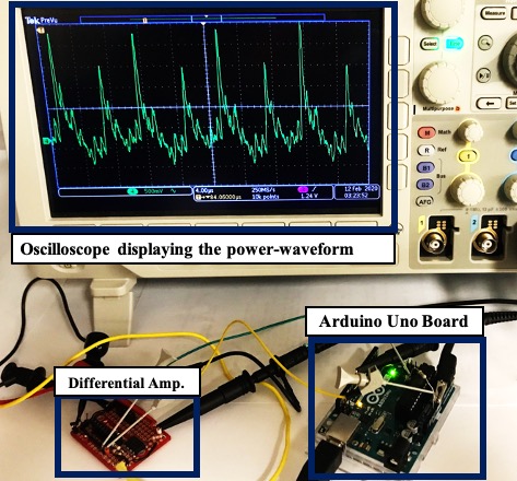
.
We demonstrated our attacks on three popular IoT platforms. Atmel ATmega328P [29] and ARM Cortex-M0+ [30] micro-processors are very popular commercial platforms for embedded applications and provide high signal-to-noise ratio (SNR) side-channel measurements. RISC-V micro-processors [31] are gaining popularity for low-power signal processing at IoT edge nodes, so we also evaluate our techniques on a custom-designed RISC-V chip [32, 33].
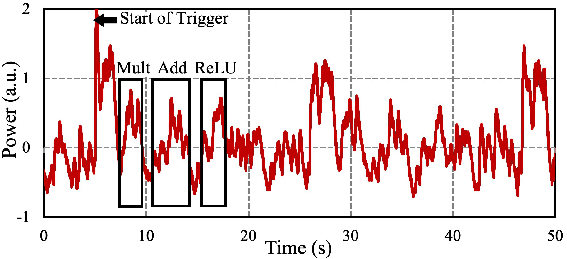
The common step for every attack is the identification of the relevant NN operations (e.g. multiplication, addition, ReLU) from the power waveform. The power waveform consists of distinct power peaks corresponding to these computations. Fig. 4 shows an example of the characteristic power waveform with multiplication, addition, and ReLU operation. A trigger signal is used to automate the data capture process through the oscilloscope. Simple signal processing techniques such as windowing, correlation, and template matching algorithms based on prior characterization can be additionally used to refine this process. [20] and [19] have described attacks that use coarse-grained parameters to extract the macro-features of the NN model (e.g. number of layers, number of neurons). In this work, we assume that these parameters are extracted using similar methods. We will instead focus on recovering the micro-parameters (e.g., weights, bias, etc).
Commercial micro-controller platforms contain peripheral units like interrupt controllers, serial communication interfaces and data converters which may significantly affect the power consumption. However, we have rigorously ensured throughout this work that none of the peripherals are active during the execution of the NN so as not to affect the identification of the NN operations from power and timing measurements. For better refining the data acquisition process, the measurements of the NN operations are synchronized using appropriate trigger signals to indicate beginning and end of the computation. This assumption models the real-life scenario quite well. In a real use-case, the micro-controller will acquire the data and then execute the NN for appropriate decision making. Therefore, with high probability, all peripheral activities will be observed only before and after the NN operation. In order to further refine the identification process, a combination of both power and EM-based signal acquisition techniques along with improved signal processing techniques can also be used.
VI Model Recovery
We will now discuss our proposed methods to extract the model parameters for neural networks with following precisions: floating point (Section VI-A), fixed point (Section VI-B), binary NNs (Section VI-C).
VI-A Floating point neural networks
Floating point NNs operate on real numbers, which are represented according to the IEEE-754 format [35]. This 32-bit number is comprised of: 1 sign bit , 8 biased exponent bits and 23 mantissa bits . The number is computed as follows, as shown in eq. 1.
| (1) |
Specifications: We will demonstrate our attack on the example neuron of TABLE VI-A (with the corresponding weights and bias displayed in its column). We will assume that the inputs are constrained to be unsigned 8-bit integers. This is very similar to that of an actual NN where the -layer neurons accepts the actual data (integer inputs). This is also the worst case scenario in terms of maximally constrained inputs (constrained to be integers). However, our discussed methodology can be applied for any choice of inputs.
| PARAMETERS | MANTISSA | ZERO | PARAMETERS |
| (ACTUAL) | (RECOVERED) | CROSS. IP. | (RECOVERED) |
| 1.0391 | |||
| 1.6641 | |||
| 1.0859 | |||
| 1.1797 | |||
| 1.1250 | |||
| Note: The cells corresponding to zero-crossover inputs , and | |||
| along with its associated recovered weights are marked in white, | |||
| light gray and dark gray colors respectively. | |||
Methodology: Steps I-IV describe the detailed methods for extracting the parameters of the layer, while step V shows how to extend it to successive layers.
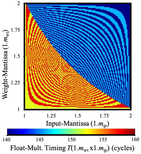
Step I. Extraction of mantissas of weights (): The timing side channel information from floating point-based multiplication operation is used to recover the weight mantissa . Let denote the time (in cycles) taken to perform the multiplication of weight and input activation . From our characterization of the floating point multiplications on the ATmega328P platform, we found that the timing of the multiplication operation is dependent on the mantissa of the operands ( and ) and is independent of the exponents involved. Hence, we can denote this mathematically as .
For a given weight mantissa , we obtain a mapping between all possible input activation mantissas and the timing of the corresponding multiplication operation . This mapping is denoted as . Fig. 5 shows the with the horizontal axis displaying and the vertical axis displaying . Each column represents the mapping corresponding to its weight mantissa . Instead of exhaustive range of , we only consider the following input mantissas of eq. 2 for constructing this look-up table (LUT).
| (2) |
As discussed earlier, the mantissa contains 23 bits. However, as shown in [20], it becomes sufficient to extract only the 7 most significant bits of the mantissa. The error introduced because of this truncation is less than 1%. Also, floating point numbers with 7 mantissa bits (instead of 23 mantissa bits), and usual 7 exponent bits and 1 sign bit, (known as bfloat16 [36]) are becoming popular. Thus, only the following weight mantissas are considered in the LUT of Fig. 5:
| (3) |
From our characterization of the floating point-based multiplication operations on the Arduino ATmega328P platform, we find that is unique for every . In other words, no two columns of Fig. 5 are same. An unknown weight mantissa is obtained by correlating its mapping with all the columns of Fig. 5 and selecting corresponding to the highest correlated column. The actual and the extracted mantissas for the example neuron are shown in TABLE VI-A, and they match very closely.
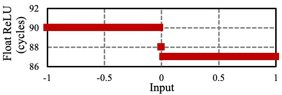
Step II. 1st round of weight and bias extraction: For the following steps, we utilize the timing side-channel of the ReLU operation. As shown in Fig. 6, the timing of the ReLU operation is dependent on the inputs. For ve inputs, the execution of the ReLU operation takes fewer cycles, whereas for ve inputs, it uses more cycles.
For determining the exponents, we utilize the concept of zero-crossover input (very similar to the concept described in [19]). We define the zero-crossover input as the valid input of for which the following equation crosses . This means that and are of opposite signs. To obtain the value of the zero-crossover input , all the other inputs except of the neuron are set to . This forces the pre-activation function to be . Now, is incremented successively from to and the timing of the ReLU operation is observed. The distinct timings of the ReLU operation for / inputs can be used to detect when changes its sign. The value of the input for which this transition occurs is the zero-crossover input . We determine the value of this zero-crossover input corresponding to every input / weight pair. However, not all input / weight pair will have a zero-crossover input. The zero-crossover input is obtained only when and are of opposite signs and . As shown in eq. 4, at zero-crossover input , , and hence can be expressed in terms of and .
| (4) |
TABLE VI-A shows the obtained for our example neuron. For many weights (e.g., ), could not be obtained because either and are of same sign or because . For these weights , the sign of the ReLU function remains unchanged for
We will now exploit the obtained values of the zero-crossover inputs to determine the value of the corresponding weights . We can determine the exponents of the weights correct only up to a constant factor. Let us select any weight with a valid value as the reference weight (e.g. for our neuron, we choose as the reference weight) and let us denote its exponent to be , that is unknown. We would now determine the exponents of all the other weights relative to . Thus, all the weights would be computed correct to the unknown factor . The exponent of the weight is obtained with respect to using eq. 5.
| (5) |
The operation of eq. 5 rounds to its nearest integer. Please refer to Appendix A-A for the derivation of the equations. The values of obtained using eq. 5 is shown in TABLE VI-A. As shown in TABLE VI-A, the estimated exponents are correct to a constant difference of . This factor of remains unknown to the attacker. We will show in Step V that the unknown scaling factor does not affect the correctness of the computation.
The value of sgn() is obtained by setting all the inputs (thus, ensuring that ) and then observing the timing of the ReLU operation. The value of sgn() for all those indexes () having valid values is opposite to that of sign(). For our example neuron, sgn() and hence, sgn()=1 for all indexes () having valid values.
The bias is obtained from eq. 4 (by using instead of generic weight ) as shown in eq. 6. This bias is calculated in TABLE VI-A.
| (6) |
Step III. 2nd round of weight extraction: In order to determine some of the remaining weights, we will use a variant of the zero-crossover input as the valid input of for which crosses . The choice of remains the same as that of Step II. In order to determine , we initialize to and all the other inputs except to . We now increment from to and observe the change in sign of the ReLU function to detect .
Extending the discussions from Step II, we find that is obtained only when sgn()=sgn() and . Following the analysis in Appendix A-A, we can obtain the unknown exponent - using eq. 7.
| (7) |
Continuing with , TABLE VI-A shows the obtained terms (marked in light-gray color) and the recovered weights for our example neuron.
Step IV. 3rd round of weight extraction: In the previous steps, we were able to recover all the weights, for which lies outside the range . In order to determine the remaining weights , we define a variant of the zero-crossover input as the valid input of for which the following equation crosses . It should be noted here that index corresponds to the input instead of , i.e. for , we have the equation changing sign. The choice of remains the same as that of Step II. Following the analysis in Appendix A-A, we can obtain the unknown sign and exponent informations using eq. 8 and eq. 9 respectively.
| (8) |
| (9) |
TABLE VI-A shows the recovered weights relative to obtained using eq. 8 and eq. 9. For , it is guaranteed that . Thus, all the weights can be determined after this step.
Step V. Model recovery from successive layers: Having determined the weights and biases of the first layer, we now successively determine weights and biases of the next layers. For detecting weight mantissas of the successive layers, we construct suitable lookup tables as per the output of the previous layer. The scaling factors for each layer will get accumulated as we reverse engineer each layer. For a feed-forward neural network, these scaling factors also do not affect the output of the comparison operation to determine the most-probable class. Hence, we can safely ignore the scaling factors while retaining the exact functionality of the original NN.
The above analysis assumes ReLU operation as the non-linear activation function. This is the worst-case situation in terms of extraction of the weights. Use of other non-linear activation functions like , , or (comparison for finding the maximum class) leaks more information from its timing side channel (as shown in Fig. 7) and hence, can be used to easily recover the unknown scaling factors.
![[Uncaptioned image]](/html/2103.14739/assets/Figures/sigmoid_atmega.jpg) |
![[Uncaptioned image]](/html/2103.14739/assets/Figures/tanh_atmega.jpg) |
VI-B Fixed point neural networks
Fixed point NNs are extremely popular from the perspective of hardware implementations because their corresponding operations can be mapped very effectively to the processor’s arithmetic hardware [4].
Assumptions: For our example neuron of TABLE VI-B, the inputs ’s are 8-bit unsigned integers, whereas the weights (’s) / bias (’s) are quantized to 4-bit / 8-bit signed integers. The pre-activations are rectified using the ReLU operation, quantized to 8-bit unsigned integer and then used as the input to the neuron for the next layer. The bit-precision of the inputs, weights and biases have been chosen here for ease of demonstration.
Methodology: The steps for recovering fixed point model parameters are described below:
Step I. Construction of the lookup table: The fixed point ReLU, similar to floating point ReLU, suffers from timing side-channel leakage depending on the sign of the operands and hence, can be used to determine the sign of (Fig. 8).
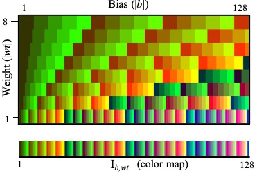
We construct a lookup table (LUT) of the zero-crossover inputs for every possible weight ()-bias () pair. Fig. 9 displays this LUT of as a color map, with the x-axis / y-axis displaying the bias / weights respectively. can be determined only when . Without loss of generality, we only consider and . Accordingly, the x-axis comprises of and the y-axis comprises of . It should be noted that this LUT is constructed independent of the targeted neuron and needs to be constructed only once.

| PARAMETERS | ZERO- | PARAMETERS | ZERO- |
| CROSSOVER | CROSSOVER | ||
| INFORMATION | INFORMATION | ||
| Note: The cells corresponding to zero-crossover inputs and are | |||
| marked in white and light gray colors respectively. | |||
Step II. Recovery of the bias: We determine the zero-crossover input (defined as the valid value of for which crosses ), for all the possible pairs of the neuron. Similar to Section VI-A, is obtained by setting all the inputs except to 0 and incrementing until the ReLU operation changes its sign (observed from its timing side channel). TABLE VI-B displays the obtained values.
From the ensemble collection of , we determine the bias by locating the column of the LUT in Fig. 9 which uniquely contains all the obtained values. TABLE VI-B shows the obtained zero-crossover inputs for our example neuron. of LUT of Fig. 9 uniquely contains all of the obtained values. By observing the timing of the ReLU operations after setting all the inputs to 0, we found that the bias is positive and hence, .
Step III. 1st round of weight recovery: After determining , we back-calculate weight from by looking at the column of the LUT corresponding to and finding the weight corresponding to . The sign of is opposite to that of the sign of bias . In this step, we were able to recover the weights for which sgn() sgn().
Step IV. 2nd round of weight recovery: To recover the remaining weights with sgn() = sgn(), we select a known weight and fix its corresponding input such that is also 8-bit signed integer but with opposite sign of . Similar to Step III in Section VI-B, we now obtain the zero-crossover input as the valid value of for which crosses .
For our example, we choose and and then obtained all possible values of in light-gray color in TABLE VI-B. From the LUT, we were able to determine from the LUT column corresponding to . For our example neuron, we were able to correctly recover the remaining weights for which sgn() sgn(). The above steps can then be applied sequentially to determine the parameters of the successive layers in layer-wise fashion.
It is important to note that for many cases, the weights / bias cannot be uniquely determined. In such situations, the attacker need to suitably determine different variants of zero-crossover inputs under different conditions .
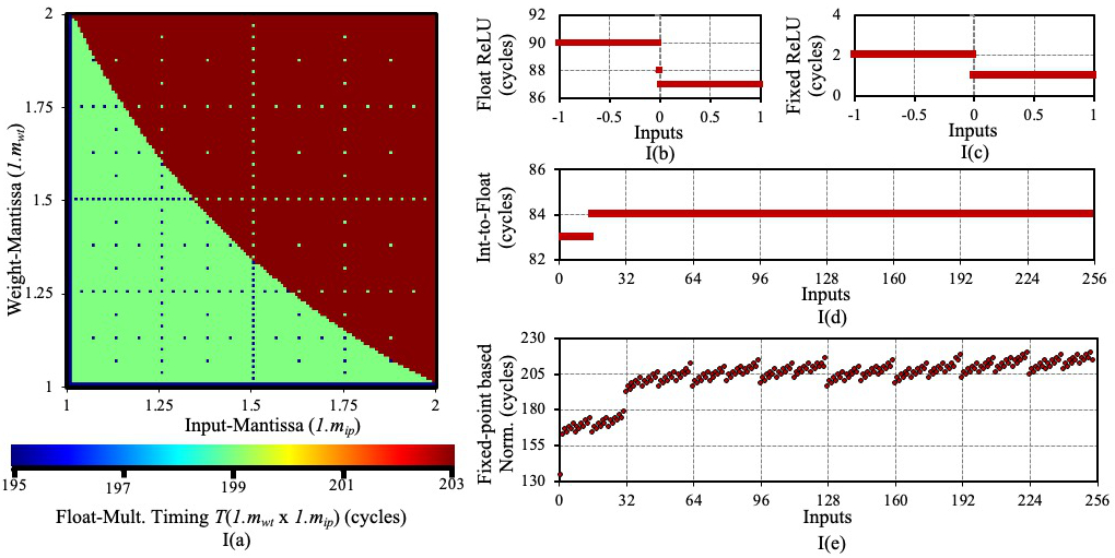
It is important to reiterate that the LUT construction is a one-time process (independent of the NN model to be used) and the same LUT can be used to recover NN parameters as many times as required, thus making our methods extremely practical. The LUT for floating point NN (shown in Fig. 5) is specific to the underlying micro-controller platform (its variants for ARM Cortex-M0+ and RISC-V RV32IM are shown in Fig. 15:I(a) and II(a) respectively), whereas the LUT for fixed point NN (shown in Fig. 9) is platform-independent.
VI-C Binary neural networks
For binary neural networks (BNNs), the weights are constrained to . However, the bias is a signed integer. Binarized neural networks [37] are a special class of BNNs where even the activations are also quantized to (except the inputs to the first layer). BNNs are popular for energy-constrained devices because of reduced memory requirements and elimination of the multiplication operation [38]. In this section, we will discuss the extraction of the model parameters of binary neural networks. The case of binarized neural network can be dealt with appropriate modifications.
| ReLU | |||||||
We will now demonstrate our methodology of the model recovery using the example neuron of Fig. 10:
Step I. Extraction of weights (): The multiplication operation comprises of either directly passing or conditional negating it (depending on whether is 1 respectively) and then adding it to . This conditional negation of (for ) leads to more number of cycles and thus, produces a timing side-channel. A major advantage is that all the weights ’s can be extracted in parallel using this information.
Step II. Extraction of bias (): After extracting, the weights ’s, we initialize the inputs such that is minimized. For our example neuron of Fig. 10, is set to and is set to . We then increment by the smallest quanta by appropriately setting the inputs, till changes its sign. This change in sign is observed by change in the timing of the ReLU operation (same as that of the fixed point ReLU operation in Fig. 8). For our example neuron, we perform this operation by decreasing to while keeping and then increasing gradually. For our example neuron, we find that changes its sign when is and is . Thus .
Step III. Extension to successive layers: We proceed successively layer-wise to recover the weights (’s) and biases (’s) using Steps I and II respectively.
We validated our attack methodology on a real 2-layer perceptron neural network for MNIST digit recognition, with different bit precisions adapted for floating point, fixed point and binary networks. For floating point, all the weights and bias were recovered with error. Exact model recovery was achieved for both fixed point and binary networks.
VII Input Recovery
We will now discuss the recovery of inputs for floating point (Section VII-A) and normalization-based (Section VII-B) NNs. Extraction of sparse inputs (e.g. MNIST [26]) for zero-skipping-based NNs is also discussed in Section VII-C. We will demonstrate our methodology for common image recognition applications which use 8-bit unsigned integers. It is important to reiterate that for input recovery, the attacker is assumed to have pre-characterized the hardware platform.
VII-A Input recovery for floating point neural networks
Any 8-bit unsigned integer input can be represented as an equivalent floating point number with its mantissa and exponent as shown below in eq. 10.
| (10) |
Step I. Extraction of mantissa (): The timing side-channel of floating point multiplication was used to recover the mantissa of the weights in Section VI-A. We adopt the same approach for extracting the input mantissa by constructing a LUT of mapping for all the possible input activation mantissas and all unique ’s in the 1st layer (that directly accepts the inputs). For an unknown input , we obtain its corresponding mapping and then match it with the pre-characterized LUT to determine .
The requirement of no prior knowledge about / is one of the major advantage of this method. The weights can be known or can be extracted using the method discussed in Section VI-A. The accuracy of mantissa extraction depends on the number of unique weight mantissas involved. All current NNs use more than sufficient number of unique mantissas in the first layer to recover all values exactly.
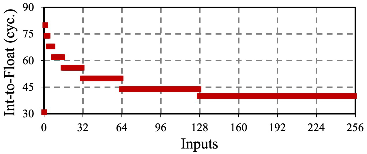
Step II. Extraction of exponent (): For floating point multiplication operation, where one operand is an integer (e.g., obtained from sensor), is first converted to floating point number and then multiplied using the conventional floating point multiplication. For the ATmega328P platform, the timing of the integer-to-float conversion can be used to recover the exponent of the input , as shown in Fig. 11. Please refer to the detailed analysis of the integer-to-float conversion process in Appendix A-B.
VII-B Input recovery using normalization operation
We propose a SPA-based input recovery method that is strictly applicable when the inputs are normalized using division operation (sometimes used during pre-processing of data). In our demonstration, the input is normalized to [0,1] using and the output is stored as a 16-bit fixed point representation . This division operation involves a series of conditional subtractions depending on the exact bit sequence of the output. Only when the quotient bit is 1, the divisor is subtracted from the dividend (as commonly done in conventional division operation). As shown in Fig. 12, bits corresponding to in give rise to a double peak in the power trace and consume more timing, which can be used to recover .
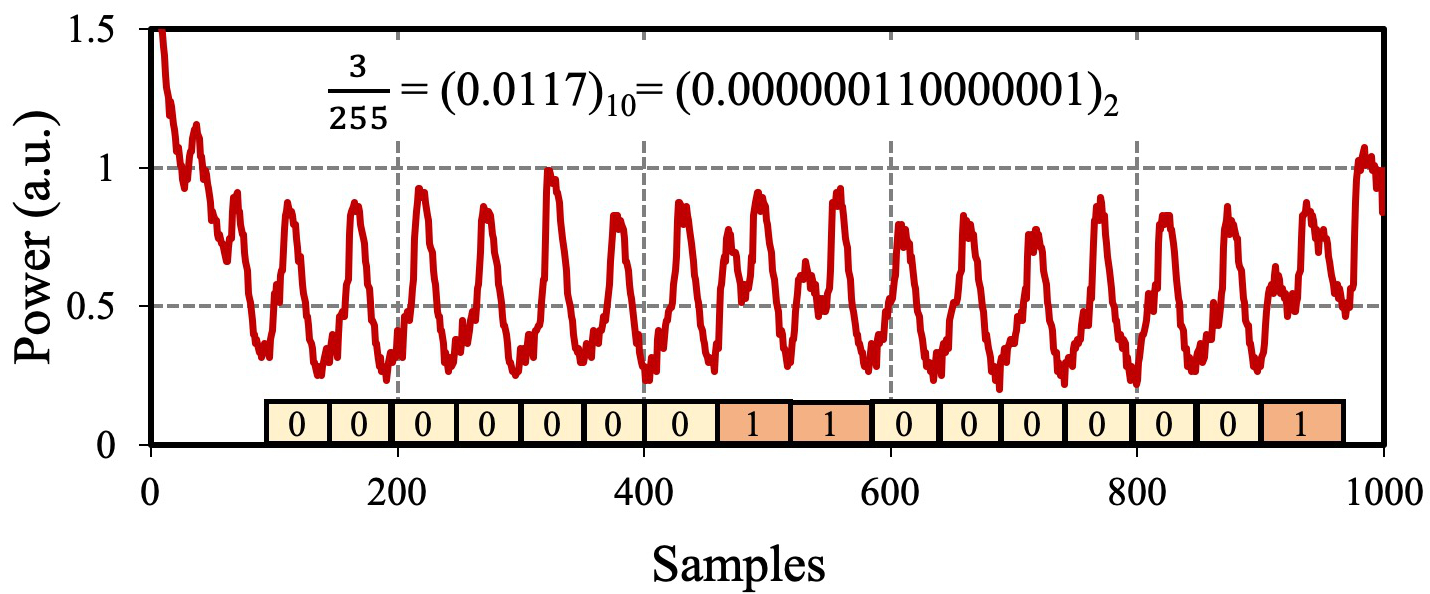
Fig. 13 shows the inputs recovered using the proposed techniques for ImageNet (“red car” and “dog”), CIFAR10 (“horse” and “ship”) and MNIST (“digit 0”) dataset. Exact input recovery was achieved in all cases for both (b) and (c).
VII-C Sparse input recovery for zero-skipping neural networks
For high energy-efficiency, zero-skipping-based neural networks do not execute any multiplication when either of the operands is 0 [39]. For , the corresponding weights are not fetched from the memory for multiplication. This timing helps to recover specialized sparse inputs like MNIST reasonably well by separating zero v/s non-zero inputs (Fig. 14). However, this method cannot be applied to general images.
| (a) Original MNIST inputs (b) Recovered MNIST inputs |
.
| Processor | Architecture | Addition | Multiplication | Division | Floating point |
|---|---|---|---|---|---|
| Atmel ATmega328P [29, 34] | 8-bit | Hardware | Hardware | Software | Software |
| (8-bit + 8-bit) | (8-bit 8-bit) | ||||
| ARM Cortex-M0+ [30, 40] | 32-bit | Hardware | Hardware | Software | Software |
| (32-bit + 32-bit) | (32-bit 32-bit) | ||||
| RISC-V RV32IM [32, 33] | 32-bit | Hardware | Hardware | Hardware | Software |
| (32-bit + 32-bit) | (32-bit 32-bit) | (32-bit / 32-bit) |
VIII Extension to Other Platforms
Next, we discuss the extensions of our previously discussed attack techniques to the following embedded platforms:
ARM Cortex-M0+: We demonstrate the attacks on the ATSAMD21G18 ARM Cortex-M0+ micro-controller [30] available in the Adafruit Metro M0 Express board [40]. It has a 32-bit architecture with a single-cycle 32-bit 32-bit hardware multiplier. It does not have a hardware floating point unit (FPU) and supports only software implementations of floating point arithmetic.
RISC-V RV32IM: We also demonstrate our attacks on a custom RISC-V micro-processor chip supporting the RV32IM instruction set [32, 33]. This processor has no hardware FPU and performs floating point operations in software. However, apart from the 1-cycle hardware multiplier, it also has a 32-cycle constant-time hardware divider, as the RV32IM instruction set includes both multiplication and division instructions.
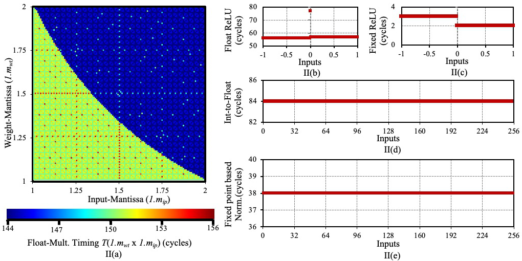
Figs. 15 (I) and (II) display the relevant timing side-channel leakages from ARM Cortex-M0+ and RISC-V processors respectively. Table VII-C also presents the specifications of the three micro-processors used for our experimental evaluations. The major observations are summarized below:
- •
-
•
The floating point ReLU (Fig. 15:I-II(b)) and fixed point ReLU (Fig. 15:I-II(c)) operations have timing side-channels differentiating positive and negative inputs. This can be used to identify zero-crossing points and hence, are in agreement with the previously described attacks (Section VI-A and VI-B).
-
•
The integer-to-float conversion process of Cortex-M0+ (Fig. 15:I(d)) has negligible information leakage. Thus, the values of the exponent cannot be determined from this timing information. Also, the floating point multiplication timing (Fig. 15:I(a)) has fewer variations and hence, a lot of weights are required to identify the input mantissas precisely. Thus, the input recovery for Cortex-M0+ is difficult to perform. The integer-to-float conversion process for RISC-V (Fig. 15:II(d)) takes constant time (irrespective of the input), hence the exponent information cannot be recovered. Hence, the extraction of inputs for floating point-based NNs is also difficult to perform on the RISC-V platform
-
•
In case of Cortex-M0+, the fixed point division operation, in software, has timing proportional to hamming weight of the output (Fig.15:I(e)), and hence can be used to recover the inputs. The custom RISC-V chip has a 32-cycle hardware divider, because of which the normalization operation takes constant time (Fig. 15:II(e)). Thus, normalization-based input recovery attacks (Section VII-B) can be prevented by having a constant-time dedicated hardware divider, albeit at the cost of increased logic area in the chip.
IX Proposed Countermeasures
Finally, we propose countermeasures against the previously discussed attacks and analyze their implementation overheads.
Floating point MAC operation: The primary reason for the timing side-channel leakage of floating point-based multiplication operation is that the output of every stage is represented according to the IEEE-754 representation [35]. So, instead of representing the numbers according to the conventional IEEE-754 representation, we alternatively represent them by equalizing the exponents with respect to the maximum exponent in the layer and storing only the modified mantissa information along with the signs. Thus, any generic floating point weight is modified to be represented in fixed point as: , which requires storage of only 3 bytes (instead of 4 bytes). For example, if the ’s of a layer are , and , we normalize them by 20 and store the weights as and respectively. The input activations (), similar to weights (), are also normalized.
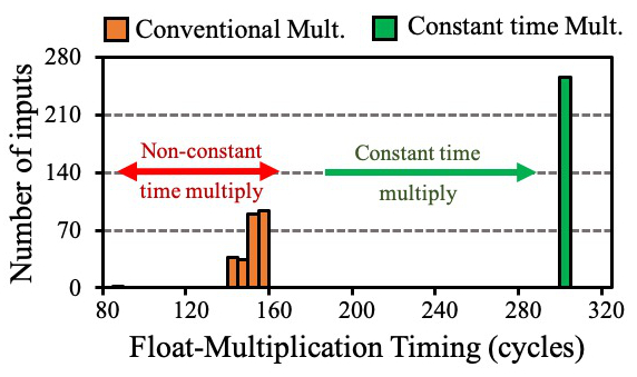
TABLE IX shows the overheads for our proposed defense for floating point operations on different platforms. The timing of the multiplication operation increased by for ATmega328P. However, the timing of an ensemble of 25 MAC operations didn’t show a proportional increase because the addition operations are now simplified to traditional fixed point signed additions.
ReLU operation: We propose the following constant-time implementation of the ReLU operation for 8-bit input :
Here, the sign bit (most significant bit) of is extracted, right-shifted and inverted to create a mask. The mask consists of all 0’s for negative inputs and all 1’s for positive inputs. This mask is AND-ed with original to compute the final output . Our proposed ReLU operation for 8-bit integer operands is shown in TABLE IX along with the intermediate values of computation. None of the intermediate steps of our proposed method is data-dependent, and hence not susceptible to timing attacks. Our proposed method is applicable to both fixed point and floating point operands (using our previously proposed representation). TABLE IX show the timings of our proposed ReLU implementation for 16-bit fixed point and 32-bit floating point inputs respectively. The additional steps lead to increase in cycle count for our proposed constant-time fixed point ReLU operation. However, the performance improves for floating point ReLU because the expensive floating point-based comparison operation is eliminated.
| out = ((pa ¿¿ 7)) & pa | ||
|---|---|---|
| pa | -12310 | 12310 |
| 100001012 | 011110112 | |
| (pa¿¿7) | 000000002 | 111111112 |
| out | 000000002 | 011110112 |
| Atmel ATmega328P | ARM Cortex-M0+ | RISC-V RV32IM | |||||
| Metric | Default | Solution | Default | Solution | Default | Solution | |
| Cycles for multiplication op. | 147.6 (avg.) | 300 | 201.3 (avg.) | 59 | 146.9 (avg.) | 8 | |
| Cycles for 25 MAC op. | 6828 | 8541 | 8406 | 2258 | 7530 | 209 | |
| Storage space for weights | 1 | 0.75 | 1 | 0.75 | 1 | 0.75 | |
| Cycles of ReLU | +ve input | 68 | 36 | 90 | 10 | 56 | 6 |
| (floating point) | 0 input | 56 | (constant time | 88 | (constant time | 77 | (constant time |
| -ve input | 61 | for any input) | 87 | for any input) | 57 | for any input) | |
| Cycles of ReLU | +ve input | 10 | 19 | 2 | 9 | 3 | 6 |
| (fixed point) | 0 input | 7 | (constant time | 1 | (constant time | 2 | (constant time |
| -ve input | 7 | for any input) | 1 | for any input) | 2 | for any input) | |
| The weights are uniformly chosen from (-1,1) and the inputs are chosen from (0,1). | |||||||
| Note: All the operation-specific cycles measurements reported in this paper may incur few extra cycles because of reading/writing of data. | |||||||
.
Input recovery: Our proposed normalized representation for floating point operands removes any timing side-channel during MAC operations. Therefore, the previously described attacks (Section VII-A) for extracting the equivalent mantissa information is no longer applicable. This is better elucidated in Fig. 16, which plots the histogram of the inputs with respect to the cycle counts for conventional and proposed multiplication operation ( and ) for ATmega328P. The variation in the timing of the conventional multiplication operation for constant leaks some information about . However, our proposed constant-time multiplication removes any timing-based leakage of inputs. Similarly, for NN with division-based input normalization, the division operation can be completely eliminated by appropriately scaling the relevant parameters of the first layer of the NN. This allows the NN to directly take in the raw inputs without the need for normalization.
X Future Work
We now discuss some future extensions of this work:
I. Extension to statistical attacks: In this paper, our primary focus was to recover the model parameters of NN using only timing side-channels and SPA. While the proposed countermeasures provide constant-time operation, they may not necessarily defend against other attacks like differential power analysis (DPA) and correlation power analysis (CPA).
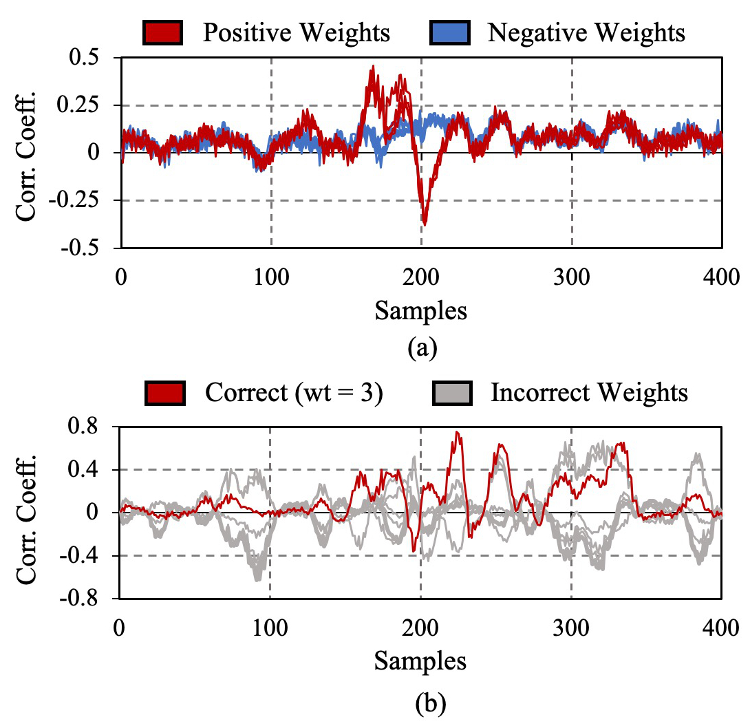
We performed CPA over the proposed constant-time fixed point multiplication operation on the Arduino ATmega328P platform. Unsigned integer inputs were provided and the byte-wise hamming weight of model was used for the CPA. Fig. 17(a) demonstrates that CPA over the most significant byte of the output was successful in identifying the sign of . Similarly, Fig. 17(b) shows that CPA over the least significant byte of the output was successful in revealing . [20, 22] describes the use of CPA and statistical techniques to recover complete neural networks.
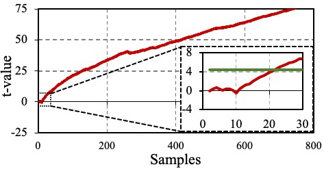
Even though the ReLU operation has been made constant time (TABLE IX), the mask consists of all ’s for ve inputs, thus leaking some information using hamming weight (and possibly power). The t-test result over the proposed ReLU operation is shown in Fig. 18. The two groups A and B contain power waveforms corresponding to randomly selected +ve and -ve inputs respectively. We get for more than 25 measurements, which proves that these two groups have distinct power signatures.
Another viable direction to explore is the use of algebraic side-channel analytic techniques [41, 42, 43]. In contrast to the conventional divide-and-conquer / statistical techniques (e.g., CPA, DPA), the algebraic techniques require minimum data complexity at the cost of more complex and sensitive computational steps. Thus, it seems that algebraic techniques might be a better choice for recovering the model parameters and statistical techniques are more suited for the input recovery attacks (real-time operation with minimal complexity at the edge nodes). The use of hybrid techniques like soft analytical side-channel attacks (SASCA) [44] also seems to be promising as it combines the low time-memory complexity and noise tolerance of standard DPA with the optimal data complexity of algebraic side-channel attacks. All the common operations execute in multiple cycles and thus, involve many intermediate steps. The dependencies between these intermediate variables make them suitable for algebraic attacks.
II. Extension to hardware platforms: The attacks which were described in this paper assume that the timings of individual NN operations can be extracted. While this condition is relatively easy to meet on embedded micro-controllers, it is very difficult to achieve in the case of custom-designed hardware units such as FPGA or ASIC platforms. For improved throughput and energy-efficiency in such hardware accelerators, the common NN operations (e.g., MAC, ReLU) are executed in parallel, using an array of processing elements (PEs). In this situation, it will be difficult to obtain the timing and power corresponding to individual operations. So, the methods described in this paper may not be directly applicable to FPGA and ASIC implementations. However, following a similar methodology with larger lookup tables and crafted inputs, it may still be possible to attack such custom hardware accelerators, and this will be explored in the future.
XI Conclusion
In this work, we have demonstrated the recovery of model parameters and inputs for common neural network (NN) implementations with different precisions, such as floating point, fixed point and binary, on three different embedded micro-controller platforms (Atmel ATmega328P, ARM Cortex-M0+ and RISC-V RV32IM) using only timing and simple power analysis side-channel attacks. Timing side-channel leakage from the multiplication and non-linear activation function computations was utilized to recover model parameters of floating point NNs. For fixed point and binary NNs, zero-crossover input information obtained from the timing side-channel of the non-linear activation function was used with strategically crafted inputs for model recovery. The inputs of floating point NNs were recovered using timing side-channel information from integer-to-float conversion and multiplication operations. Input recovery for fixed point NNs with input normalization was performed using simple power analysis (SPA) attack on the division operation. We have also proposed software countermeasures against these side-channel attacks and analyzed their implementation overheads.
The feasibility and simplicity of our attacks, with minimal storage and computation requirements, emphasize the side-channel security concerns of embedded neural network implementations and the need for defending against them. The performance overheads of our proposed software-based countermeasures also motivate the design of custom side-channel-resistant hardware for embedded neural network accelerators.
Acknowledgment
The authors acknowledge the funding support from Analog Devices and Texas Instruments. The authors sincerely thank Dr. Samuel H. Fuller, Prof. Vivienne Sze, Maitreyi Ashok and Kyungmi Lee for their valuable suggestions. The authors are also thankful to the editors and the anonymous reviewers for their insightful comments which helped improve the quality of the paper.
Appendix A Appendix
A-A Extended analysis of floating point model extraction
Dividing eq. 4 by eq. 11, expressing in terms of mantissa, sign and exponent and using the fact that sgn()sgn() we obtain eq. 12-14.
| (12) |
| (13) |
| (14) |
Here round of to the nearest integer.
(2) Derivation for 2nd round of weight extraction:
For the definition of we have:
| (15) |
| (16) |
Rearranging eq. 11 and eq. 16 (by eliminating ), expressing in terms of mantissa, sign and exponent and using the fact that sgn()sgn(), we obtain eq. 17-18.
| (17) |
| (18) |
(3) Derivation for 3rd round of weight extraction:
For the definition of we have:
| (19) |
| (20) |
A-B Analysis of integer-to-float conversion for ATmega328P
The integer-to-float conversion process for ATmega328P is explained in the form of a pseudo-code in Algorithm 1. Relevant comments are shown alongside using symbol.
Explanation: For an 8-bit unsigned integer , the exponent is initialized to the maximum possible value () and the mantissa is set to . Throughout the code, it is ensured that is equal to . To convert to the IEEE-754 [35] representation, the mantissa needs to lie between . Hence is left shifted ( 2) and the exponent is reduced by 1, until . The number of times the while loop in lines 4-7 of Algorithm 1 gets executed directly depends on the exponent, as shown in Figure 11.
References
- [1] A. Krizhevsky et al., “ImageNet Classification with Deep Convolutional Neural Networks,” in NeurIPS, 2012.
- [2] N. Tajbakhsh et al., “Convolutional Neural Networks for Medical Image Analysis: Full Training or Fine Tuning?” IEEE T-MI, 2016.
- [3] O. E. David et al., “DeepChess: End-to-End Deep Neural Network for Automatic Learning in Chess,” in ICANN, 2016.
- [4] V. Sze et al., “Efficient Processing of Deep Neural Networks: A Tutorial and Survey,” Proceedings of the IEEE, 2017.
- [5] K. Y. R. Lu et al., “Wearable System-on-Module for Prosopagnosia Rehabilitation,” in IEEE CCECE, 2016.
- [6] C. Qiu et al., “A Wireless Wearable Sensor Patch for the Real-Time Estimation of Continuous Beat-to-Beat Blood Pressure,” in IEEE EMBC, 2019.
- [7] S. Maji et al., “A Low-Power Dual-Factor Authentication Unit for Secure Implantable Devices,” in IEEE CICC, 2020.
- [8] A. Gural et al., “Memory-Optimal Direct Convolutions for Maximizing Classification Accuracy in Embedded Applications,” in ICML, 2019.
- [9] I. Fedorov et al., “SpArSe: Sparse Architecture Search for CNNs on Resource-Constrained Microcontrollers,” in NeurIPS, 2019.
- [10] S. Heller et al., “Hardware Implementation of a Performance and Energy-optimized Convolutional Neural Network for Seizure Detection,” in IEEE EMBC, 2018.
- [11] J. Maier et al., “Real-Time Patient-Specific CT Dose Estimation using a Deep Convolutional Neural Network,” in 2018 IEEE NSS/MIC, 2018.
- [12] R. Shokri et al., “Membership Inference Attacks Against Machine Learning Models,” in IEEE Symp. on Security & Privacy, 2017.
- [13] A. Chakraborty et al., “Adversarial Attacks and Defences: A Survey,” arXiv preprint arXiv:1810.00069, 2018.
- [14] S. J. Nass et al., “The Value and Importance of Health Information Privacy,” in Beyond the HIPAA Privacy Rule: Enhancing Privacy, Improving Health Through Research. National Academies Press, 2009.
- [15] R. Spreitzer et al., “Systematic Classification of Side-Channel Attacks: A Case Study for Mobile Devices,” IEEE Commun. Surv. Tutor., 2018.
- [16] P. C. Kocher, “Timing Attacks on Implementations of Diffie-Hellman, RSA, DSS, and Other Systems,” in IACR CRYPTO, 1996.
- [17] J.-F. Dhem et al., “A Practical Implementation of the Timing Attack,” in Int. Conf. on Smart Card Research and Adv. Appl., 1998.
- [18] U. Banerjee et al., “Power-based Side-Channel Attack for AES Key Extraction on the ATMega328 Microcontroller,” MIT Computer Systems Security, 2015.
- [19] W. Hua, Z. Zhang, and G. E. Suh, “Reverse Engineering Convolutional Neural Networks Through Side-channel Information Leaks,” in ACM/ESDA/IEEE DAC, 2018.
- [20] L. Batina et al., “CSI NN: Reverse Engineering of Neural Network Architectures Through Electromagnetic Side Channel,” in USENIX Security Symposium, 2019.
- [21] L. Wei et al., “I Know What You See: Power Side-Channel Attack on Convolutional Neural Network Accelerators,” in ACM ACSAC, 2018.
- [22] L. Batina et al., “Poster: Recovering the Input of Neural Networks via Single Shot Side-channel Attacks,” in ACM CCS, 2019.
- [23] G. Dong et al., “Floating-Point Multiplication Timing Attack on Deep Neural Network,” in IEEE SmartIoT, 2019.
- [24] E. Brier et al., “Correlation Power Analysis with a Leakage Model,” in IACR CHES, 2004.
- [25] C. Clavier et al., “Horizontal Correlation Analysis on Exponentiation,” in ICICS, 2010.
- [26] Y. LeCun et al., “MNIST Handwritten Digit Database,” 1999.
- [27] A. Krizhevsky et al., “CIFAR-10 (Canadian Institute for Advanced Research),” 2009.
- [28] J. Deng et al., “ImageNet: A Large-Scale Hierarchical Image Database,” in CVPR09, 2009.
- [29] Microchip Technology Inc., “ATmega328P Datasheet.”
- [30] Microchip Technology Inc. , “ATSAMD21G18 Datasheet.”
- [31] Z. Li et al., “Design and Implementation of CNN Custom Processor Based on RISC-V Architecture,” in IEEE HPCC/SmartCity/DSS, 2019.
- [32] U. Banerjee et al., “An Energy-Efficient Reconfigurable DTLS Cryptographic Engine for Securing Internet-of-Things Applications,” IEEE JSSC, 2019.
- [33] U. Banerjee et al., “Sapphire: A Configurable Crypto-Processor for Post-Quantum Lattice-based Protocols,” IACR TCHES, 2019.
- [34] Arduino, “Arduino Uno Rev3.”
- [35] “IEEE Standard for Floating-Point Arithmetic,” IEEE Std 754, 2019.
- [36] D. Kalamkar, et al., “A Study of BFLOAT16 for Deep Learning Training,” arXiv preprint arXiv:1905.12322, 2019.
- [37] M. Courbariaux et al., “Binarized Neural Networks: Training Deep Neural Betworks with Weights and Activations Constrained to +1 or -1,” arXiv preprint arXiv:1602.02830, 2016.
- [38] E. Nurvitadhi et al., “Accelerating Binarized Neural Networks: Comparison of FPGA, CPU, GPU, and ASIC,” in FPT, 2016.
- [39] S. Han et al., “EIE: Efficient Inference Engine on Compressed Deep Neural Network,” in ACM/IEEE ISCA, 2016.
- [40] Adafruit Industries, “Adafruit METRO M0 Express – Designed for CircuitPython – ATSAMD21G18.”
- [41] S. Mangard, “A Simple Power-Analysis (SPA) Attack on Implementations of the AES Key Expansion,” in ICISC, 2002.
- [42] K. Schramm et al., “A Collision-Attack on AES,” in IACR CHES, 2004.
- [43] A. Bogdanov et al., “Algebraic Methods in Side-Channel Collision Attacks and Practical Collision Detection,” in IACR INDOCRYPT, 2008.
- [44] N. Veyrat-Charvillon et al., “Soft Analytical Side-Channel Attacks,” in IACR ASIACRYPT, 2014.
![[Uncaptioned image]](/html/2103.14739/assets/Figures/image_recovery.jpg)