[acronym]long-short \setabbreviationstyleshort-long
Beamforming in LEO Constellations for NB-IoT Services in 6G Communications
Abstract
With the first commercializations of 5G networks, Beyond 5G (B5G), or 6G, systems are starting to be defined. In this context, Internet of Things (IoT) services will be even more impactful with respect to 5G systems. In order to cope with the huge amount of IoT devices, and the potentially large capacity requirements for the most advanced of them (e.g., live camera feeds from first responders in emergency scenarios), non-terrestrial systems will be pivotal to assist and complement the terrestrial networks. In this paper, we propose a multi-layer non-terrestrial architecture for NarrowBand-IoT (NB-IoT) services based on GSO and Non Geosynchronous Orbit (NGSO) nodes. To cope with both the number of devices and the potentially large capacities, we propose to implement Minimum Mean Square Error (MMSE) beamforming in an aggressive full frequency reuse scenario. The performance assessment shows the significant benefits of the proposed solution.
Index Terms:
NB-IoT, Satellite Communications, beamforming, B5G, 6G, mega-constellationsI Introduction
While the vast potential of 5G networks is starting to drive the global economy and society, the race towards Beyond 5G (B5G), or 6G, mobile communications has already started, [1, 2]. The evolution of 5G into 6G networks is aimed at responding to the increasing need of our society for ubiquitous and continuous connectivity services in all areas of our life: from education to finance, from politics to health, from entertainment to environment protection. The requested applications and services pose a vast variety of requirements calling for a flexible, adaptable, resilient, and cost efficient network able to serve heterogeneous devices with different capabilities and constraints. In this context, the technologies for 6G networks will include both novel concepts, as Terahertz communications and intelligent communication environments (e.g., intelligent surfaces), and the full exploitation of solutions initially adopted for 5G, e.g., Artificial Intelligence (AI) and Satellite Communications (SatCom), [3, 4, 5].
Internet of Things (IoT), as a widespread system interconnecting not only things, but also people, processes, and data, is already taking a central role in 6G. Recognising this, since Rel. 13, 3GPP introduced a number of key features to provide a progressively improved support to Low Power Wide Area Network (LPWAN) with EC-GSM-IoT and LTE-eMTC, [29, 30]. More recently, NarrowBand-IoT (NB-IoT) has been introduced, aiming at, among the others, [31, 32]: i) supporting ultra-low complexity devices for IoT; ii) improving the indoor coverage; iii) supporting a massive number of connections ( per cell-site sector); and iv) improving the battery efficiency. It shall be noticed that this is actually a new technology and, thus, not fully backward compatible with legacy 3GPP devices. Based on the lessons learnt from the initial 5G deployments and on the global societal and network trends, the translation from human-centric towards machine-centric communications will be even more pronounced in 6G. In fact, it is expected that the number of Machine-To-Machine (M2M) connections will increase from 8.9 billions in 2020 to 14.7 billions in 2023, representing one third of the global devices, [15]. In addition, also the total traffic is going to intensify, motivated by the deployment of advanced services, e.g., telemedicine and smart transportation, which might require larger bandwidths compared to wearables and sensor networks. Both in terms of connections and bandwidth, terrestrial networks alone might not be able to satisfy the demanding IoT requirements in the near future. In addition, another vital requirement for an infrastructure providing IoT services is that of guaranteeing ubiquitous connectivity to the low-cost, low-powered devices distributed all over the globe. This again might be a challenge for terrestrial IoT, since there are vast areas where a terrestrial infrastructure is unfeasible or not economically viable.
In this framework, the integration of satellite and terrestrial networks can be a cornerstone to the realisation of the foreseen heterogeneous global 6G system. Thanks to their inherently large footprint, satellites can efficiently complement and extend dense terrestrial networks, both in densely populated areas and in rural zones, as well as provide reliable Mission Critical services; these aspects, and the related technical challenges, are being extensively addressed in academic research and funded projects, [6, 7, 8, 9, 10, 11, 12]. The added value of a Non-Terrestrial Network (NTN) component in the overall system architecture has also been recognised by 3GPP, which officially approved two Work Items aimed at integrating NTN in the 5G architecture starting from Rel. 17, [13, 14]. In this context, several studies and funded projects are addressing the integration of satellite and terrestrial communications for IoT services, [16, 17, 18]. In [19], an overview of the IoT scenarios and use cases in which satellite systems can play a key role is provided. The authors of [20] focus on Low Earth Orbit (LEO)-based IoT services, analyzing the possible use cases and proposing a constellation design. In [21], the authors study the LoRa adaptability in the IoT use case for LEO satellites. In [22], the authors explore the potential of SatCom systems in 5G Machine Type Communications (MTC). In [23], the authors provide a detailed analysis on the link budget calibration for NB-IoT based on 3GPP specifications. An overview of the possible challenges of NB-IoT over NTN is reported in [24]. An analysis on the Doppler and delay induced by non-geostationary satellites is reported in [25, 26, 27]. Finally, [28] addresses the design of a NB-IoT receiver in the presence of Doppler effects at the gateway side.
In this paper, we focus on the implementation of beamforming techniques in Non Geosynchronous Orbit (NGSO) constellations for NB-IoT services. As previously introduced, the main challenges are related to providing ubiquitous connectivity also in remote areas and supporting a massive number of IoT devices, potentially with large bandwidth requirements. For these reasons non-terrestrial (NT) systems can provide a valuable resource for 6G IoT services to support and complement terrestrial networks. In this context, traditional frequency reuse approaches, e.g., 3 or 4 colours, might not be sufficient, thus calling for more aggressive solutions as full frequency reuse. To deal with the significantly increased interference due to the antenna side-lobes, advanced interference management techniques, as beamforming, precoding, and Multi-User Detection (MUD), are needed. During the last years, the implementation of beamforming techniques in SatCom has been extensively addressed for Geostationary Earth Orbit (GEO) systems, mainly, but also for LEO constellations, [33, 34, 35, 36, 37, 38] and references therein. In these works, the objective has been that of increasing the overall throughput in unicast or multicast systems, also addressing well-known issues for SatCom-based beamforming as scheduling and Channel State Information (CSI) retrieval. In this paper, we propose an advanced system architecture for NT-based IoT services and implement beamforming solutions to show the benefit that can be obtained for IoT services.
II Non-terrestrial NB-IoT architecture
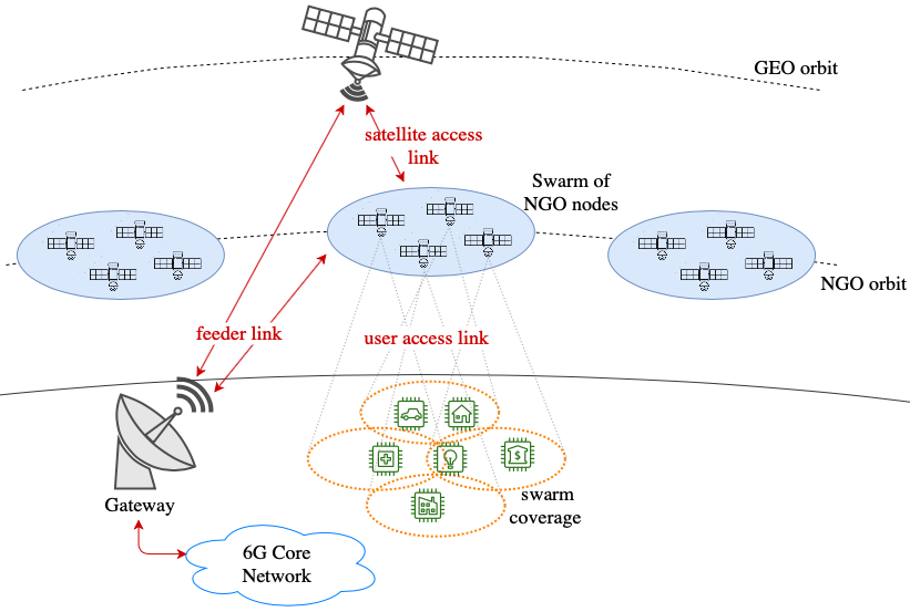
Building on the multi-layered NT network introduced in [8], we propose the system architecture showed in Fig. 1:
-
•
The terrestrial segment is composed by the 6G terrestrial network infrastructure, which is connected to the NT segment through a set of on-ground Gateways (GWs). The GWs have to be properly distributed around the globe so as to guarantee that at least one GW is always in Field Of View (FOV) of one of the elements in the non-terrestrial segment, i.e., a GSO or NGSO element. Each GW manages a set of 6G base stations, which we refer to as future generation NodeB (fgNB), to avoid confusion with 5G legacy gNBs; the fgNBs are thus conceptually located at the GW. In this context, it shall be highlighted that: i) with transparent payloads in the NT elements, the on-ground fgNB implements the full protocol stack; ii) with regenerative payloads, functional split solutions can be considered, thus separating the fgNB protocol stack between the on-ground central unit (CU-fgNB) and the flying distributed unit (DU-fgNB). The implementation of functional split and the type of split depend on the complexity and capabilities of the NT segment.
-
•
The access segment is assumed to be deployed as a multi-layer NT network, i.e., with elements located on different orbits, including GSO and NGSO. Focusing on the latter, depending on the considered altitude, various elements can be launched: LEO or very Low Earth Orbit (VLEO) satellites, CubeSats, High Altitude Platform Stations (HAPS), balloons, etc.; given the very diverse characteristics and performance they have, we generically refer to these elements as NGSO nodes. As highlighted in Fig. 1, these nodes are connected to the terrestrial segment through a GSO satellite or by directly connecting to the visible GWs. Each node is able to serve a portion of the on-ground coverage area by means of a single-beam or multi-beam system, depending on the payload. It shall be noticed that, for the sake of clarity, we represented one NGSO layer only, but more can be envisaged, based on a proper trade-off between the system requirements and its complexity.
-
•
In the on-ground user segment, a plethora of IoT devices is distributed all over the world and they are served by the NGSO nodes through the user access link. As previously mentioned, these devices potentially have heterogeneous requirements depending on the type of service. Notably, both one-way uplink and two-way IoT is possible. In the former case, the typical scenario is that of an enormous amount of IoT devices requiring both limited capacities, as location (e.g., smart transportation, automotive, good and freight tracking, etc.) and monitoring measurements (e.g., energy production in smart grids, farmland sprinkler irrigation), and larger ones, as live feeds from security cameras or first responders in an emergency scenario. In the latter case, there is a growing pervasiveness for bidirectional communications, including, but not limited to, wearable devices (e.g., answering to text or calls from a smart-watch), smart homes (e.g., remote control of connected devices), and Mission Critical scenarios (e.g., sending live feeds from the first responders to the control center). In addition, it shall also be considered that in many scenarios the distributed measurements from IoT sensors are collected in a centralised unit that controls and optimises the system behaviour by reconfiguring the actuators (which can be embedded in the same sensing IoT device or separately), e.g., optimisation at city or even regional level of a smart energy distribution grid, [39, 40].
The type of connection between the terrestrial and the access segments depends on both the complexity of the on-ground network, i.e., the number of GWs that can be deployed, and the position of the NGSO nodes on the orbit; in fact, it will happen during one orbit period that the nodes are moving over areas where the visibility with a GW might be difficult (very low elevation angles) or not possible at all and, thus, the connection with a GSO satellite shall be guaranteed to ensure communications with the core network. Clearly, where possible, both connections (GW and GSO) can be considered to cooperatively work. With respect to the air interface to be used on these links, the type of payload, i.e., transparent or regenerative, and the possible presence of functional split have to be considered. To better detail this aspect, it is reasonable to assume that similar approaches in the standardisation will be used for 6G as those implemented in 5G. Thus: i) with a transparent payload, the connection between the GWs and the NGSO nodes, as well as that between GSO and NGSO, shall be based on the same air interface of the user access link, discussed below; ii) with regenerative payloads, the air interface shall be that between a fgNB and the core network without functional split (NG air interface in 5G systems) or that interconnecting the central and distributed units of the fgNB (F1 interface in 5G). It is worth mentioning that, in the latter case, the NG and F1 interfaces can be assumed to be logical ones as for legacy 5G systems, i.e., as long as proper signalling is ensured, they can be implemented by means of any Satellite Radio Interface (SRI), e.g., DVB-S2, [41], DVB-S2X, [42], or DVB-RCS, [43].
In terms of the user access link, it shall be highlighted that the on-ground IoT devices do not have visibility of all of the NGSO nodes for the entire time. In particular, depending on the nodes’ location along the orbit, for a given on-ground coverage area, only a subset of nodes will be able to communicate with the IoT devices. Based on this observation, the NGSO nodes are grouped into NGSO swarms, i.e., groups of NGSO nodes that are serving, through their combined single-/multi-beam footprints, a specific on-ground area for the current orbital position. The previously discussed connection between the NGSO nodes and the core network is to be thus intended as a connection at swarm level; in this context, in case a single node of the swarm is able to connect to a GW, either the whole swarm is also served through the proposed GSO satellite or Inter-Node Links (INLs) have to be considered to ensure proper coordination. If not otherwise specified, we assume the 3GPP NB-IoT air interface on the user access link without affecting the generality of our work; however, other options are also possible, e.g., SigFox or LoRa.
III System Model
In the proposed multi-layer non-terrestrial system, we focus on the user access downlink towards the NB-IoT devices. If not otherwise specified, in the following we assume that: i) a swarm of single-beam NGSO nodes is serving the on-ground IoT devices based on a full frequency reuse scheme; ii) on-ground Minimum Mean Square Error (MMSE) beamforming is implemented at the system GW, which is assumed to ideally know the NB-IoT CSI; and iii) in the time-frequency resource grid, which is licit to be assumed for 6G, during each time slot, devices are randomly scheduled in each kHz NB-IoT carrier, i.e., one device per beam. Focusing on a generic time slot, the signal received by the -th device of the -th beam can be written as:
| (1) |
where: i) , is the vector of complex unit-variance transmitted symbols; ii) is the maximum transmission power from each NGSO node; iii) is a complex circularly-symmetric Gaussian random variable with zero-mean and unit variance; and iv) represents the channel vector of the -th device in the -th beam. The channel coefficient between the -th user in the -th beam and the -th satellite is:
| (2) |
in which: i) and represent the transmitting and receiving antenna gains between the -th satellite and the -th user in the -th beam; ii) the transmitting antenna gain is a function of , the angle between the -th satellite antenna boresight and the direction of the -th user in the -th beam; iii) the receiving antenna gain is a function of , the angle between the antenna boresight of the -th user in the -th beam and the -th satellite; iv) models the antenna losses; v) is the slant range between the -th user in the -th beam and the -th satellite; vi) is the carrier wavelength; and vii) is the noise power. Please note that the unit variance assumption for the Gaussian noise in (1) is licit since the channel coefficients are normalised to the noise power . Finally, is the MMSE beamforming matrix computed as:
| (3) |
where is the vector of regularisation factors, with , [44]. The above MMSE beamforming matrix is computed at each time slot based on the devices to be served. It is worth highlighting that specific power constraints are usually taken into account when computing the precoding matrix; these are aimed at regularising the combination of the transmitted power level from each on-board antenna so as to satisfy power constraint requirements, [38]. In the considered system, we are implementing MMSE by means of a distributed antenna system, in which the antennas are located on-board the NGSO nodes; thus, rather than typical constraints focusing on the limitation of the overall power, we consider those in which the power per transmitting satellite is upper-bounded to :
-
•
Per Antenna Constraint (PAC): the maximum power per satellite is fixed to , but the orthogonality among the MMSE matrix columns is degraded, leading to a loss in the performance due to an increased interference level.
(4) -
•
Maximum Power Constraint (MPC): the power per satellite is upper bounded to , but the orthogonality among the MMSE matrix columns is kept; in this case, one satellite is exploiting the maximum power , while the others are transmitting lower power levels.
(5)
Based on the above considerations and assumptions, the Signal-to-Interference plus Noise (SINR) at the -th device in the -th beam can be computed as:
| (6) |
From this, the achieved rate can be evaluated either from the Shannon formula or from the adopted Modulation and Coding (ModCod) scheme. It is worth highlighting that the above model is valid independently from the type of NGSO node that is considered. Moreover, even though we are focusing on the MMSE approach, other beamforming algorithms or normalisations can be easily included.
IV Numerical Results
While the proposed architecture is valid for a node constellation with global coverage, in the following we focus on a single NGSO swarm of LEO satellites in circular polar orbit. Each satellite is equipped with a single-beam antenna pointed towards the corresponding Sub Satellite Point (SSP); we are thus assuming the moving beams scenario, [13], i.e., the beams move together with the satellites along their orbit. For the swarm design, the following procedure is implemented: 1) , i.e., the angle at which the transmission radiation pattern is equal to dB, for the considered antenna configuration is computed; 2) the beam radius is obtained in -coordinates as ; 3) an hexagonal lattice is generated for the SSPs; 4) based on Earth-satellite geometry considerations, the inter- and intra-node separation angles, among orbits and satellites in the same orbit, respectively, are obtained for the considered altitude, providing the needed orbital parameters for the swarm design.
| Parameter | Value | Units |
|---|---|---|
| antenna model | NTN, [14] | - |
| 0 | dBi | |
| antenna temperature | K | |
| noise figure | dB |
| Parameter | km | km | Units | ||
| Set a | Set b | Set a | Set b | ||
| antenna diameter | m | ||||
| dBi | |||||
| EIRP density | dBW/MHz | ||||
| - | |||||
The simulation parameters are reported in Tables I and II for the NB-IoT devices and the LEO satellites, respectively. We assume a system operating in S-band at GHz, in which, as per 3GPP specifications, MHz can be assumed as channel bandwidth; thus, exploiting a full frequency reuse approach with beamforming, approximately NB-IoT devices can be simultaneously served with Frequency Division Multiplexing (FDM). As for the NB-IoT devices, it is worth mentioning that omni-directional antennas are considered, [45], and, thus, , . As for the losses modelled in , the following terms are included, [13]: i) the NB-IoT devices are linearly polarised, [45], and, thus, an additional dB loss is considered; ii) dB are introduced by ionospheric scintillations; and iii) dB are included as shadowing margin. As for the location of the NB-IoT devices, at each of the Monte Carlo iterations, we assume them to be uniformly distributed with a density user/km2; at each iteration, all of the considered users are served. In this context, it is worth to highlight that the user density is below the values expected in densely populated areas, while it is reasonable for remote regions; however, since we are assuming moving beams and considering ideal CSI at the GWs, this assumption does not affect the generality of the numerical results: the transmission on each carrier is a snapshot at the current swarm location of a uniform distribution of NB-IoT devices.
IV-A Performance assessment
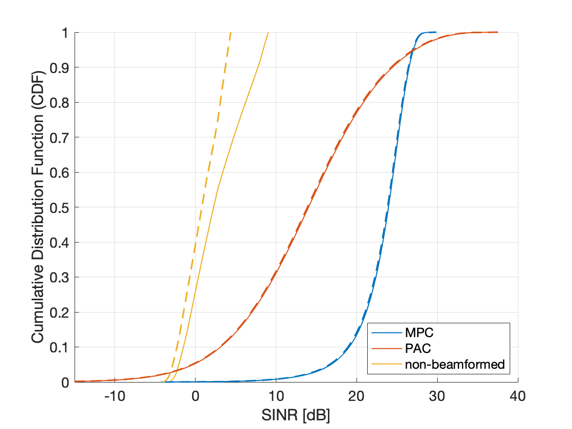
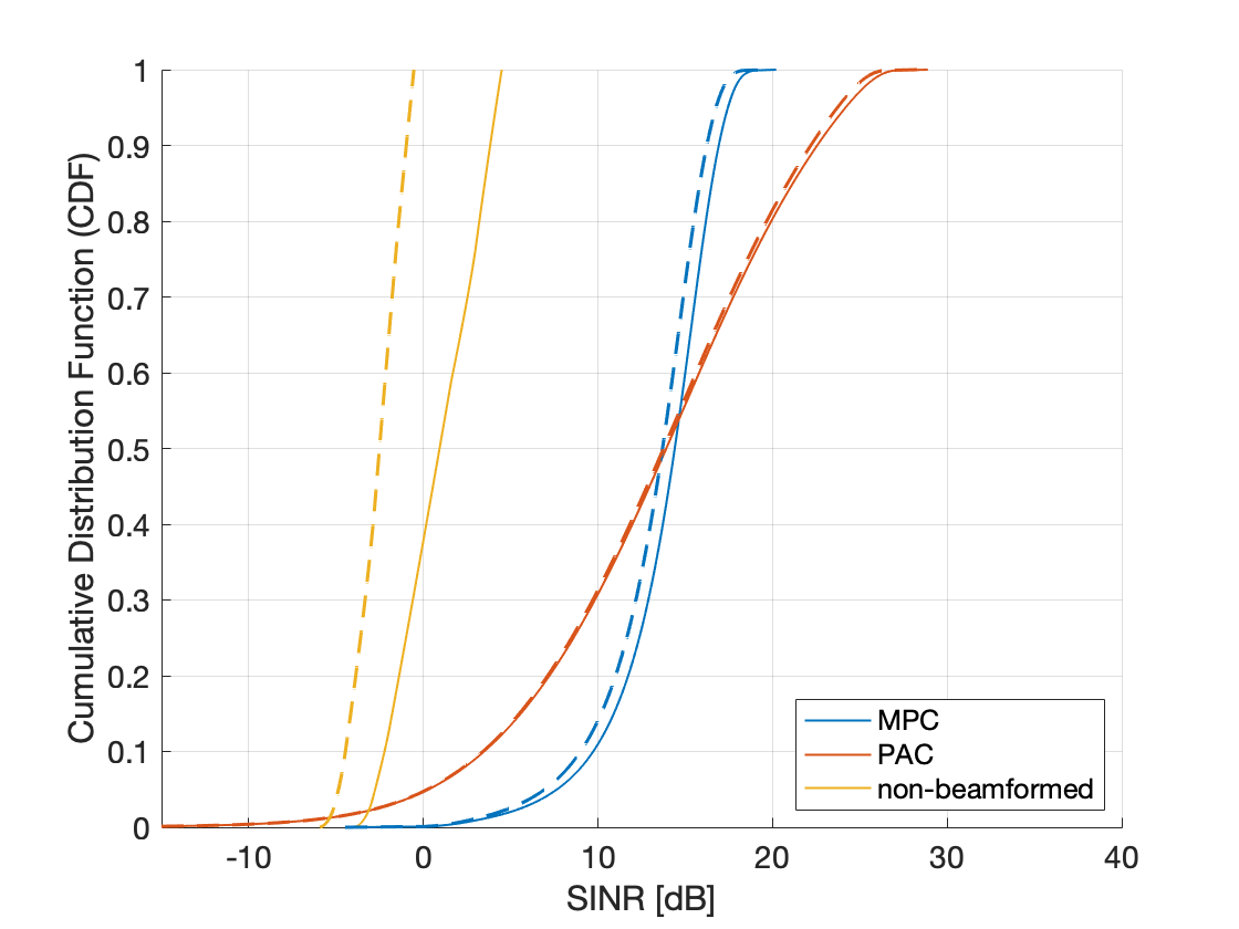
In Fig. 2 and 3 we report the Cumulative Distribution Function (CDF) of the Shannon spectral efficiency per user. Focusing on set a (Fig. 2), we can notice that:
i) the performance with beamforming is significantly better compared to the non-beamformed case, with SINR values that go up to dB for in the former case, compared to less than dB in the latter;
ii) the performance of MPC is better in terms of fairness, with a CDF slope much steeper than PAC;
iii) with PAC, the maximum achievable SINR is slightly better; and
iv) the performance with beamforming is almost identical for both and km orbits.
When set b (Fig. 3) is considered, with less directive antennas, similar considerations hold; the only difference is that the performance at km is slightly worse with respect to km orbits, in the order of less than dB. Comparing the performance with set a and set b, MPC provides a better performance with set a; this is motivated by observing that this set has a larger antenna gain; thus, since with MPC onl one satellite is transmitting at , the lower transmission power of the other satellites that keeps the optimality of the MMSE solution is compensated.
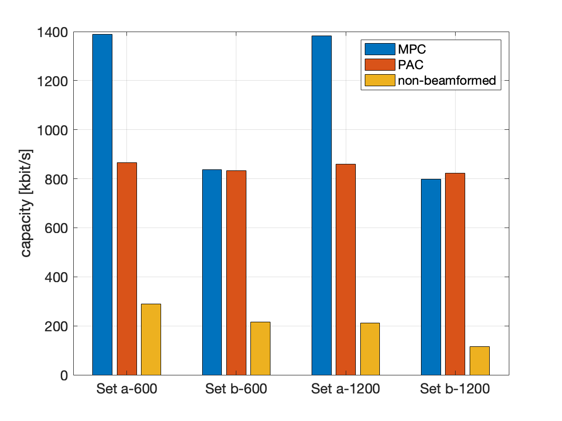
In Fig. 4, the average capacity in the scenarios detailed in Table II, assuming one NB-IoT carrier per user, i.e., kHz per user; it shall be noticed that, in case larger capacities are requested from some devices (as discussed in the previous sections), more carriers can be assigned by the system scheduler. It can be noticed that the trends highlighted in the SINR CDFs are confirmed:
1. the MPC normalisation provides a significantly better performance with respect to PAC at km ( vs kbit/s), while at km they are similar;
2. the benefit of beamforming is significant, with gains up to for MPC at km.
Comparing the performance with set a and set b, it can be noticed that MPC is significantly better at km compared to PAC, while at km they are almost identical. Finally, it shall be noticed that these capacity values are sufficient for low-capacity NB-IoT devices, but in case larger capacities are needed, more carriers can be aggregated.
IV-B Technical challenges and future works
The numerical assessment discussed above provides a valuable insight on the benefit that beamforming techniques can bring into future 6G NB-IoT services. However, there are several technical challenges that still need to be addressed in future extensions of this work:
-
•
The numerical assessment has been performed with ideal CSI and considering a single swarm. More accurate analyses have to be performed assuming non-ideal CSI, i.e., by taking into account the capabilities of the NB-IoT devices to estimate the channel vectors and to provide these measurements to the GWs, which poses power consumption challenges due to both the estimation and the transmission of the CSIs back to the GWs; the consideration of non-ideal CSI also allows to take into account the fact that, due to the swarm high speed on low orbits, those used at the GW are likely to be outdated with respect to the actual channel condition. Moreover, multiple swarms will be considered to also take into account the increased interference coming from adjacent NGSO nodes in other swarms.
-
•
The NGSO swarm constellation has been designed assuming the central node on the equatorial line; when the nodes move to different latitudes, due to the circular polar orbit characteristics, they will tend to be closer to each other and, thus, an increased overlap of the on-ground footprint will arise. This aspect has to be taken into account since it affects the beamforming performance.
-
•
In this work, we focused on the downlink for two-way IoT services. However, also uplink transmissions pose challenges in terms of number of connections and potentially large bandwidth. In this context, uplink Cooperative MultiPoint (CoMP) techniques or distributed on-ground solutions as crowd-sourcing approaches.
-
•
The user distribution in IoT services can be strongly non-uniform; in particular, in densely populated areas thousands of devices can be present per square km, while in rural areas there are likely to me much less devices.
These aspects will be thoroughly addressed in future extensions of this work.
V Conclusions
In this paper, we proposed a multi-layer non-terrestrial architecture for NB-IoT services based on GSO and NGSO nodes. To deal with the huge number of NB-IoT devices and the potentially large bandwidth requirements, MMSE beamforming has been proposed. The performance assessment has been discussed in terms of both SINR CDF and average capacity, showing that MMSE beamforming with different normalisation can bring significant benefits. Moreover, the main technical challenges related to the proposed architecture, including non-ideal CSI and full global coverage, have been detailed and will be addressed in future works.
References
- [1] ITU-R FG-NET-2030, ”Network 2030 - Gap Analysis of Network 2030 New Services, Capabilities and Use cases”, Jun. 2020.
- [2] M. Latva-aho, K. Leppänen, ”Key Drivers and Research Challenges for 6G Ubiquitous Wireless Intelligence”, 6G Flagship, Sep. 2019.
- [3] I. F. Akyildiz, A. Kak, S. Nie, ”6G and Beyond: The Future of Wireless Communications Systems”, IEEE Access, vol. 8, pp. 133995-134030, Jul. 2020.
- [4] H. Viswanathan, P. E. Mogensen, ”Communications in the 6G Era”, IEEE Access, vol. 8, pp. 57063-57074, Mar. 2020.
- [5] M. Z. Chowdhury et al., ”6G Wireless Communication Systems: Applications, Requirements, Technologies, Challenges, and Research Directions”, IEEE Op. J. of the Commun. Soc., vol. 1, pp. 857-975, Jul. 2020.
- [6] A. Guidotti et al., ”Architectures and Key Technical Challenges for 5G Systems Incorporating Satellites”, IEEE Trans. on Veh. Tech., vol. 68, no. 3, pp. 2624-2639, Mar. 2019.
- [7] A. Guidotti et al. ”Architectures, standardisation, and procedures for 5G Satellite Communications: A survey”, Computer Networks, vol. 183, Dec. 2020.
- [8] A. Vanelli-Coralli et al., ”5G and Beyond 5G Non-Terrestrial Networks: trends and research challenges”, IEEE 5G World Forum, pp. 165178-165200, Sep. 2020.
- [9] B. G. Evans, The role of satellites in 5G, ASMS/SPSC Conference, pp. 197-202, Sep. 2014
- [10] SaT5G (Satellite and Terrestrial Network for 5G), EU H2020 5GPPP Phase II project, https://www.sat5g-project.eu/.
- [11] ESA project SATis5G (demonstrator for satellite-terrestrial integration in the 5G context), https://artes.esa.int/projects/satis5-0.
- [12] 5G-VINNI (5G Verticals INNovation Infrastructure), EU H2020 5G PPP Phase III project, https://www.5g-vinni.eu/.
- [13] 3GPP TR 38.821, ‘Solutions for NR to support Non-Terrestrial Networks (NTN)”, 2020.
- [14] 3GPP TR 38.811, ”Study on new radio (NR) to support non-terrestrial networks”, 2019.
- [15] Cisco, ”Cisco Annual Internet Report (2018-2023)”, Mar. 2020.
- [16] ESA Project E2UT (Energy Efficient User Terminals for Massive Uncoordinated Access via Satellite), https://artes.esa.int/projects/e2ut
- [17] ESA Project NB-IoT4Space (3GPP Narrow-Band Internet-of-Things (NB-IoT) User Sensor Integration into Satellite), https://artes.esa.int/projects/nbIoT4space
- [18] ESA Project IoT SATBACK (Satellite Backhauling Prototype for Future Narrow Band Internet of Things (NB-IoT) Networks), https://artes.esa.int/projects/IoT-satback
- [19] M. De Sanctis et al., ”Satellite Communications Supporting Internet of Remote Things”, IEEE Internet Things J., vol. 3, no. 1, pp. 113–123, Feb. 2016.
- [20] Z. Qu et al., ”LEO Satellite Constellation for Internet of Things”, IEEE Access, vol. 5, pp. 18391–18401, Aug. 2017.
- [21] T. Wu et al., ”Research on LoRa Adaptability in the LEO Satellites Internet of Things”, 2019 IEEE IWCMC, pp. 131–135, Jun. 2019.
- [22] S. Cioni et al., ”On the Satellite Role in the Era of 5G Massive Machine Type Communications”, IEEE Network, vol. 32, no. 5, pp. 54-61, Sep. 2018.
- [23] M. Conti et al., ”NB-IoT over Non-Terrestrial Networks: Link Budget Analysis”, 2020 IEEE Globecom, pp. 1-6, Dec. 2020.
- [24] M. Gineste et al., ”Narrowband IoT Service Provision to 5G User Equipment via a Satellite Component”, 2017 IEEE Globecom, pp. 1-4, Dec. 2017, pp. 1–4.
- [25] O. Kodheli et al., ”Resource Allocation Approach for Differential Doppler Reduction in NB-IoT over LEO Satellite”, ASMS/SPSC, pp. 1-8, Sep. 2018
- [26] O. Kodheli et al., ”An Uplink UE Group-Based Scheduling Technique for 5G mMTC Systems Over LEO Satellite”, IEEE Access, vol. 7, pp. 67413–67 427, May 2019.
- [27] M. Conti et al., ”Doppler Impact Analysis for NB-IoT and Satellite Systems Integration”, 2020 IEEE ICC, pp. 1-7, Jun. 2020.
- [28] S. Cluzel et al., ”3GPP NB-IoT Coverage Extension Using LEO Satellites”, 2018 IEEE VTC Spring, pp. 1–5, Jun. 2018.
- [29] 3GPP TR 45.820, ”Cellular system support for ultra-low complexity and low throughput Internet of Things (CIoT)”, Nov. 2015.
- [30] 3GPP TSG RAN Meeting #69, RP-151621, ”Narrowband IoT (NB-IoT)”, Sep. 2015.
- [31] Y.-P. E. Wang et al., ”A Primer on 3GPP Narrowband Internet of Things”, IEEE Commun. Mag., vol. 55, no. 3, pp. 117–123, Mar. 2017.
- [32] R. Ratasuk et al., ”Overview of narrowband IoT in LTE Rel-13”, 2016 IEEE CSCN, pp. 1-7, Oct. 2016.
- [33] P.-D. Arapoglou et al., ”MIMO over Satellite: A Review”, IEEE Commun. Surv. & Tut., vol. 13, no. 1, pp. 27-51, 2011.
- [34] G. Gallinaro et al., ”Perspectives Of Adopting Inteference Mitigation Techniques In The Context Of Broadband Multimedia Satellite Systems”, AIAA Int. Commun. Sat. Syst. Conf., Sep. 2005.
- [35] L. You et al., ”Massive MIMO Transmission for LEO Satellite Communications”, IEEE J. on Sel. Ar. in Commun., vol. 38, no. 8, Aug. 2020.
- [36] A. Guidotti, A. Vanelli-Coralli, ”Clustering strategies for multicast precoding in multibeam satellite systems”, Int. J. on Sat. Commun. and Netw., vol. 38, no. 2, Jul. 2019.
- [37] A. Guidotti, A. Vanelli-Coralli, ”Geographical Scheduling for Multicast Precoding in Multi-Beam Satellite Systems”, ASMS/SPSC, Sep. 2018.
- [38] A. Guidotti, A. Vanelli-Coralli, ”Design Trade-Off Analysis of Precoding Multi-Beam Satellite Communication Systems”, 2021 IEEE Aerospace Conference, accepted, Jan. 2021.
- [39] A. Meloni, L. Atzori, ”The Role of Satellite Communications in the Smart Grid”, IEEE Wir. Commun., vol. 24, no. 2, pp. 50-56, Apr. 2017.
- [40] D. Chang et al., ”Smart satellites in Smart Grids”, 2014 IEEE SmartGridComm, pp. 487-492, Jan. 2015.
- [41] ETSI EN 302 307-1, ”Digital Video Broadcasting (DVB); Second generation framing structure, channel coding and modulation systems for Broadcasting, Interactive Services, News Gathering and other broadband satellite applications; Part 1: DVB-S2”, Jul. 2014.
- [42] ETSI EN 302 307-2, ”Digital video broadcasting (DVB); Second generation framing structure, channel coding and modulation systems for broad- casting, interactive services, news gathering and other broadband satellite applications; Part 2: DVB-S2 extensions”, May 2009.
- [43] ETSI EN 301 790, ”Digital Video Broadcasting (DVB); Interaction channel for satellite distribution systems”, Feb. 2015.
- [44] R. Muharar, J. Evans, ”Downlink Beamforming with Transmit-side Channel Correlation: A Large System Analysis”, IEEE Int. Conf. on Commun. (ICC), Jun. 2011.
- [45] 3GPP TSG RAN Meeting #103-e, RP-2009098, ”Discussion on scenarios applicable to NB-IoT NTN”, Nov. 2020.