Experimental SWAP test of infinite dimensional quantum states
Chi-Huan Nguyen
Ko-Wei Tseng
Gleb Maslennikov222Present address: NKT Photonics, Bregnerødvej 144, 3460 Birkerød, DenmarkH. C. J. Gan
Centre for Quantum Technologies, National University of Singapore, 3 Science Dr 2, 117543, Singapore
Dzmitry Matsukevich
Centre for Quantum Technologies, National University of Singapore, 3 Science Dr 2, 117543, Singapore
Department of Physics, National University of Singapore, 2 Science Dr 3, 117551, Singapore
Abstract
Efficient overlap estimation of high-dimensional quantum states is an important task in quantum information and a core element in computational speedups of quantum machine learning. Here we experimentally demonstrate the SWAP test that measures the overlap of two motional states in a system of trapped ions.
To illustrate the versatility of our implementation, we report the overlap measurement of a variety of quantum states: Fock states, coherent states, squeezed vacuum states, and cat states.
We highlight applications of the SWAP test by measuring the purity of mixed states.
Our results enable quantum information processing with high dimensional quantum states.
Estimation of the overlap between two quantum states and is a frequently encountered task in quantum information processing Ekert et al. (2002), quantum computations Lau and Plenio (2016), quantum machine learning Biamonte et al. (2017) and quantum neural networks Zhao et al. (2019). It enables quantum fingerprinting Buhrman et al. (2001); Horn et al. (2005) which determines whether two -bit strings are identical in steps. Used in some implementations of variational quantum eigensolvers Higgott et al. (2019), it is also an integral part of the quantum support vector machines Rebentrost et al. (2014a). Several important properties of quantum systems such as the fidelity, the purity, the Hilbert-Schmidt distance, and the Renyi entropy can be derived from the overlap estimation Nielsen and Chuang (2010); Filip (2002); Islam et al. (2015); Linke et al. (2018).
A brute force approach to estimating the overlap is first reconstructing the density matrices of quantum states and using state tomography, followed by calculating Nielsen and Chuang (2010). As the dimension of the Hilbert space increases, the number of operations required for full state tomography grows exponentially, making this technique computationally costly Cotler and Wilczek (2020).
Alternatively, if the unitary transformation to prepare the quantum state starting from the initial state is known, one can measure the overlap by applying the inverse unitary transformation to the other state and measure the probability that the final state is Ouyang et al. (2020); Johri et al. (2020); Peters et al. (2021).
A universal and constant-depth circuit measuring the overlap between quantum states, that are not known a priori, would provide quantum advantages for several quantum machine learning algorithms Rebentrost et al. (2014b); Lau et al. (2017); Schuld and Killoran (2019).
This can be realized using the SWAP test that relies on the controlled SWAP gate Buhrman et al. (2001) and have been implemented with qubits on various platforms such as photons Cai et al. (2015); Trávníček et al. (2019), trapped ions Linke et al. (2018), and superconducting qubits Cincio et al. (2018).
On the other hand, computation can also be carried out with continuous variables (CV) Braunstein and van
Loock (2005) or a hybrid approach Andersen et al. (2015) that utilizes both discrete and continuous degrees of freedom of a quantum system. This approach which was pioneered in optics Yoshikawa et al. (2008) provides hardware-efficiency, as the same apparatus can encode and process more information using the states of harmonic oscillators if they are inherently available.
For states of bosonic modes, the SWAP test Filip (2002); Garcia-Escartin and Chamorro-Posada (2013) was first demonstrated using dispersive coupling between a transmon and superconducting cavities Gao et al. (2018, 2019). The motional modes of trapped ions are another well-controlled bosonic system for exploring quantum information processing over infinite dimensions Ortiz-Gutiérrez et al. (2017); Leibfried et al. (2003); Um et al. (2016); Kienzler et al. (2017); Toyoda et al. (2015).
In this Letter, we demonstrate the SWAP test of high dimensional quantum states encoded in the motional modes of trapped ions.
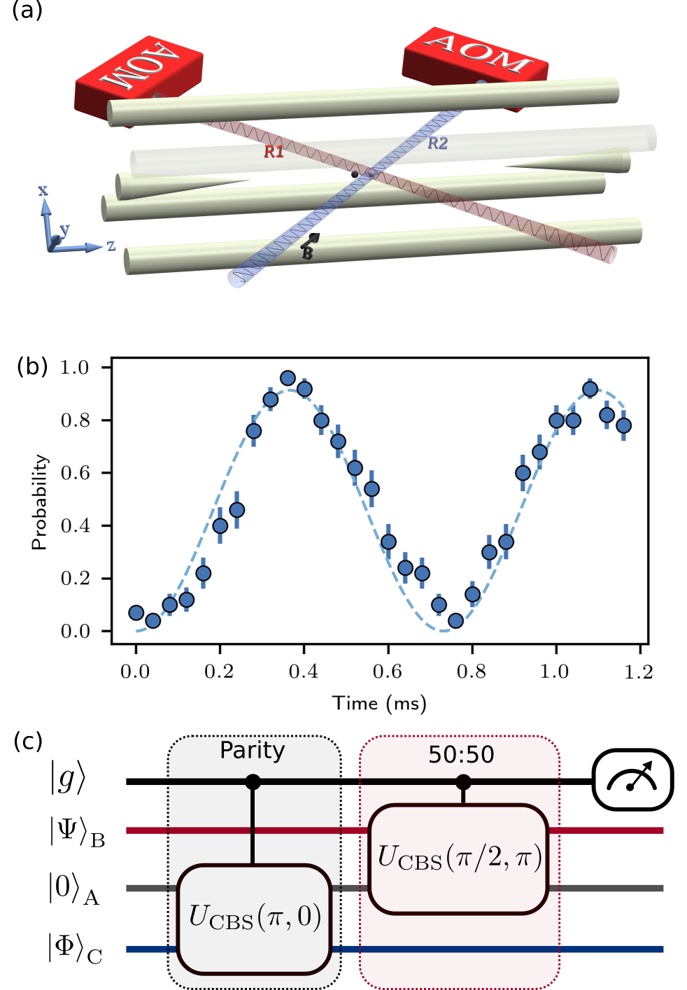
Figure 1:
(a) Experimental setup. A linear rf-Paul trap confines two ions. Raman beams represented by blue and red beams form a running optical lattice at the ions. The beat note frequency and amplitude of the lattice are controlled by rf signals sent to acousto-optical modulators (AOMs) in each Raman beam.
(b) Measured as a function of the spin-dependent beam splitter gate duration. Error bars correspond to statistical uncertainty and denote one standard error of the mean.
The dashed line shows the fit to the sine function to extract the coupling strength of the beam splitter gate.
(c) SWAP test circuit to measure the overlap of motional states prepared in mode and .
In our experiment, two ions are confined in a linear rf-Paul trap.
The secular trapping frequencies are MHz and actively stabilized with a drift of less than Hz/ hour.
We encode the information into the out-of-phase motion in the direction (mode ), out-of-phase and in-phase motion in the direction (mode and respectively) (Fig 1a). The motional mode frequencies are MHz.
To mediate the interaction between motional modes, two hyperfine levels of one ion are used as qubits, denoted as and .
Here, and denote the quantum numbers associated with the total atomic angular momentum and its projection along the quantization axis defined by an applied magnetic field of 5.2 G, respectively.
The transition frequency of internal states is GHz.
Standard optical pumping and resonance fluorescence state detection techniques are used to initialize and detect the qubits Olmschenk et al. (2007).
The other ion is optically pumped to the metastable state by driving the transition at nm. This “dark” ion does not interact with the optical fields during the experiment.
We employ a stimulated Raman process to coherently control the qubit as well as the motion states of ions.
A frequency-doubled, mode-locked Ti:sapphire laser (pulse duration 3 ps, repetition rate 76 MHz) produces a pair of optical beams that are responsible for the Raman transition via the internal states and Hayes et al. (2010).
The detuning and the pulse shape of the Raman beams are controlled by acousto-optical modulators (AOMs) (Fig. 1a).
The single qubit rotation is performed by tuning the Raman beat-note to qubit resonance .
Here, .
Measurement of motional states is done by coupling to the qubit via the blue (bsb) or red (rsb) motional sideband pulses which are described by the time evolution of the Hamiltonians and , where and .
The building block for the SWAP test is the spin-dependent beam splitter gate Gan et al. (2020) that induces the interaction
(1)
between two modes of motion conditional on the internal states of the ions denoted as and .
Here, and are the annihilation (creation) operator of the motional modes and . represents an experimentally tunable phase, the coupling strength, and denotes an effective mixing angle for a gate duration .
We achieve the beam splitter transformation between modes and by driving simultaneously two Raman transitions with beat-note frequencies tuned to .
To reduce off-resonant coupling to the carrier transition, the actual waveform that is applied on the AOMs to implement have smooth rising and falling edges with a time constant us, and a constant amplitude in the middle.
The SWAP test is implemented as a combination of two spin-dependent beam splitter gates followed by the measurement of the qubit state as shown in the Fig 1c. The qubit is initially prepared in the state where are the eigenstates of the operator. After the first gate the creation operators evolve as , conditioned on the qubit being in the state . If the mode is initially in the vacuum state and mode has excitations, this transfers population of the mode to and introduces an additional factor , acting as a parity gate for the state .
The second operator acts as the spin-dependent 50:50 beamsplitter and transforms modes and as
,
, depending on the state of the control qubit.
The outcome of the qubit measurement cannot be changed by the unitary transformation of only motional modes after the second gate.
A combination of spin-independent 50:50 beamsplitter gate between mode and and a 100:0 beamsplitter gate between mode and would return modes to the vacuum state, and , to the initial state if the control qubit is in state , while transforming modes and as , if the qubit is in the state . This is equivalent to the controlled SWAP gate. The overlap of the states in mode and is then given by , where is the probability to detect the qubit in state Buhrman et al. (2001) (see Supplementary Material for a detailed proof).
A typical experiment sequence starts with 4 ms of Doppler cooling followed by 10 ms of Sisyphus cooling Ejtemaee and Haljan (2017).
The radial motional modes are further sideband cooled to the ground states.
The heating rates are .
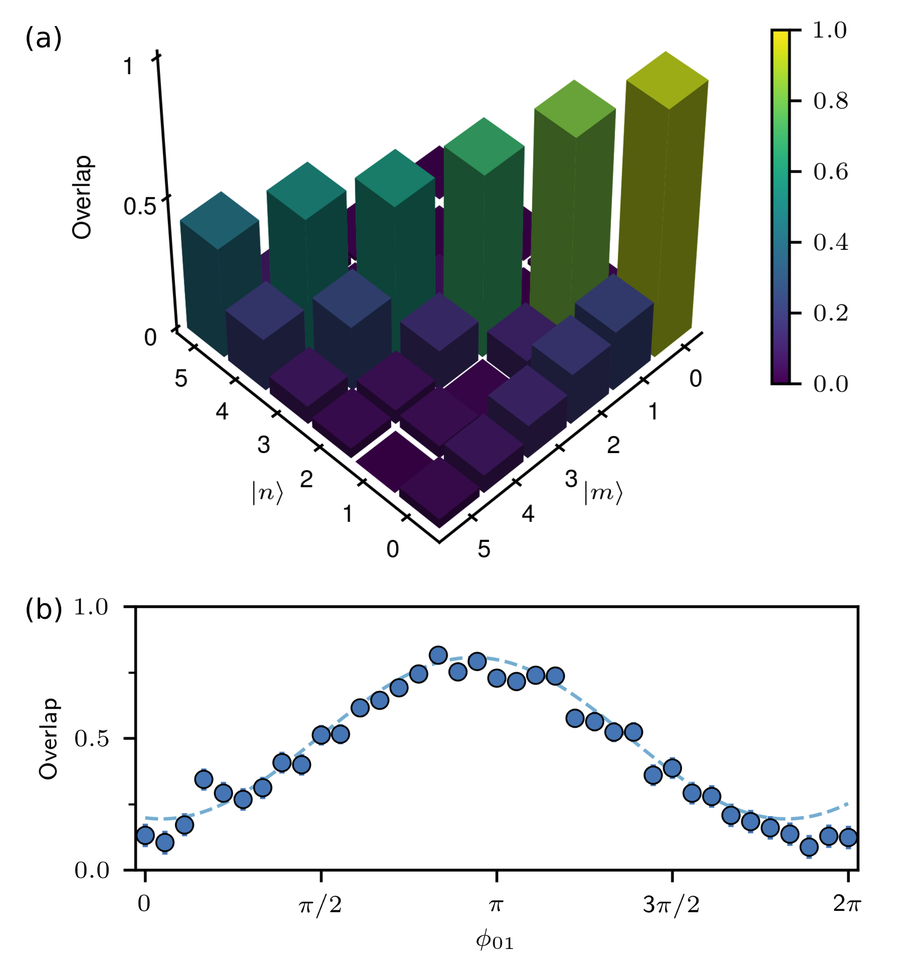
Figure 2:
SWAP test of finite-dimensional quantum states. (a). Measured overlap of Fock states and
(b). Overlap of the and as a function of the relative
phase difference . Error bars correspond to statistical uncertainty and denote one standard errors of the mean. The solid line fits the data points to a sine function.
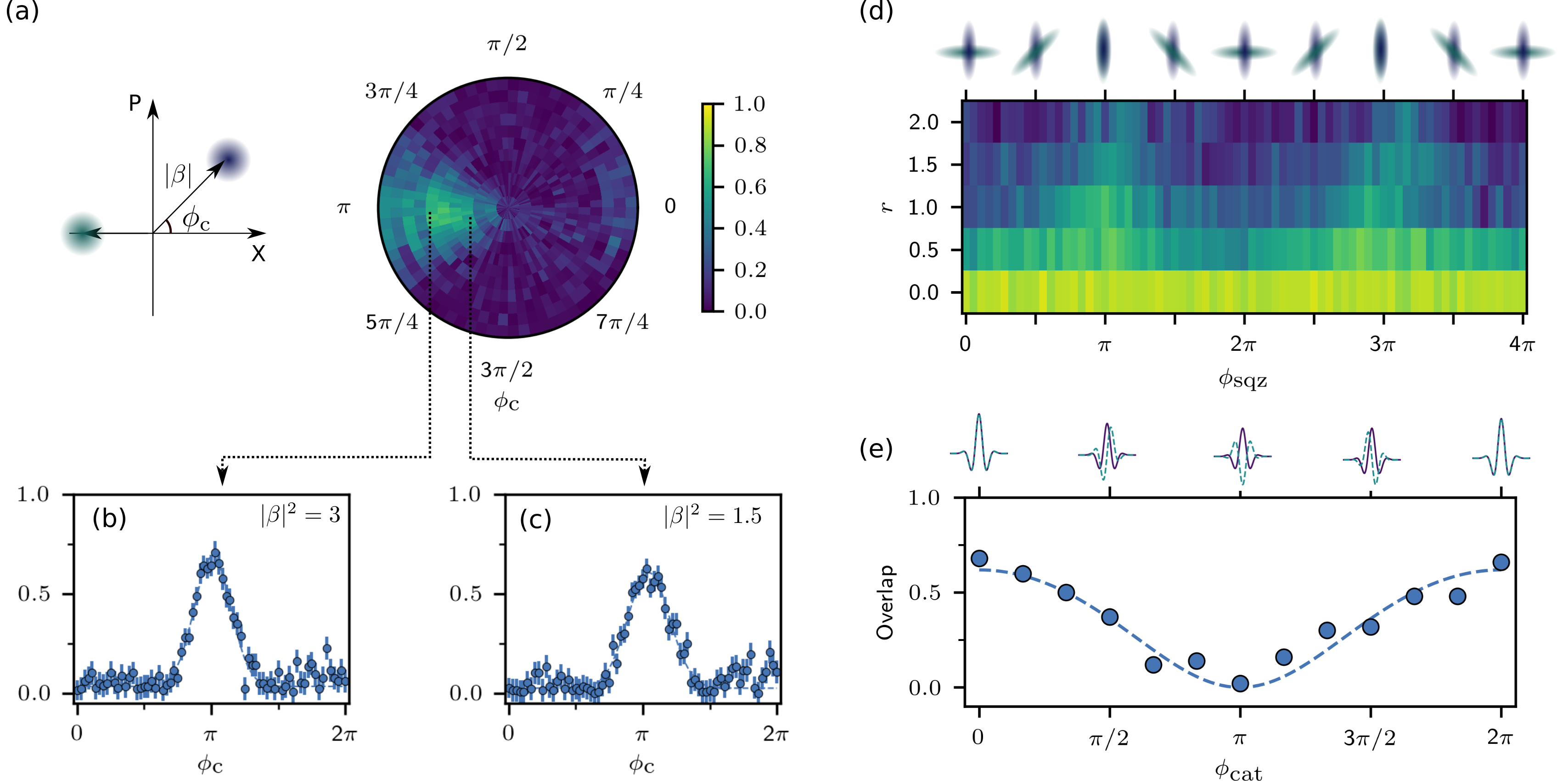
Figure 3:
SWAP test of infinite-dimensional quantum states. (a) Measured overlap of coherent states and as a function of the relative displacement angle , for and .
1D cuts at displacements (b) and (c) .
The dashed lines fit the data to a Gaussian function.
(d) Overlap of the squeezed vacuum states and .
Top row shows the illustrated Wigner functions.
(e) Measured overlap of cat states and
for , as a function of a variable phase difference .
Top row shows the imaginary part of Wigner functions of cat states.
The dashed line is a fit to the overlap function of cat states (see text). All error bars correspond to statistical uncertainty and denote one standard error of the mean.
We characterize the coupling strength by applying to the input state and measure the probability to detect the internal state in , denoted as .
Figure 1b shows the measured probability as a function of the gate duration along with a sinusoidal fit with fitting parameters and .
The coupling strength Hz corresponds to implementing a beam splitter operation in s. A total time required for the SWAP test of ms, is independent of the dimension of the input state and is much shorter than the ms motional phase coherence time for the superposition of Fock states .
We highlight the versatility of our method by measuring the overlap of a variety of quantum states using the same time sequence and parameters for the SWAP test circuit.
We begin with Fock states and , for .
The result shown in Fig. 2a agrees with the expected outcome of high overlap probability along the diagonal.
We observed an increase in the overlap between and . Figure 2b shows the result of the SWAP test of superposition states and
as a function of relative phase difference , along with a fit to a sinusoidal function.
We highlight the state-independence of the SWAP test by estimating the overlap of high-dimensional states such as coherent states, squeezed vacuum states, and cats states as shown in Fig. 3.
We prepared these families of states using spin-dependence forces that results from a running optical lattice formed by the Raman beams Ding et al. (2014).
Figure 3a presents the overlap measurements of coherent states and .
As indicated in Fig. 3b and c, the maximum overlap is observed at the (mod ) and .
We also observe a noticeable overlap at , that can be attributed to the imperfect state preparation.
Figure 3d presents results of SWAP test of squeezed vacuum states and , where is the squeezing parameter.
The overlap peaks measured as a function of becomes sharper as increases.
Using the techniques reported in Ding et al. (2017); Kienzler et al. (2016), we prepare the cat states and
for and sequentially in mode and respectively.
Figure 3e presents their overlap as a function of relative parity angle .
For , the overlap function of the cat states has a form of
(2)
where represents the reduction of the overlap due to technical imperfections of our experiment.
From a fit of the overlap to Eq. 2 with two free parameters and (dashed line in Fig. 3e), we obtain and the coherent amplitude , which agrees with the independently measured values of and using the standard methods of motional state detection Leibfried et al. (2003).
We believe reduction of the overlap observed here, besides the technical imperfections of the experiment, is also caused by the faster decoherence of the cat states due to dephasing and motional heating.
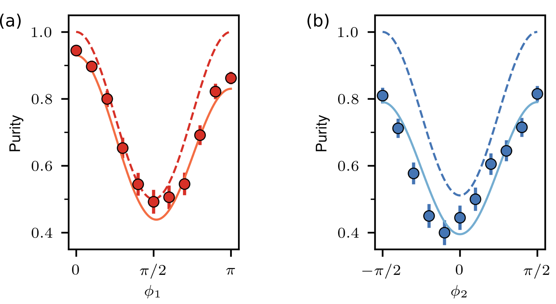
Figure 4:
Measurement of purity of quantum states. (a) Measured purity of .
(b) Measured purity of cat states where . Error bars correspond to statistical uncertainty and denote one standard error of the mean.
Dash lines show expectation of purity for an ideal experiment, whereas solid lines take into account the reduction of measured overlap due to technical imperfection of the experiment (see text).
An important application of SWAP test is the measurement of purity of quantum states .
For the same density matrix prepared in mode and , the overlap of these two modes is equivalent to the purity of , defined as Ekert et al. (2002).
We demonstrate the purity measurement of quantum states that has a density matrix
, where and are orthogonal. We prepare these states by entangling the internal states with the motional states, followed by optical pumping of the internal states (see Supplementary Material).
Figure 4a shows the measured purity of as is varied from to .
The experimentally obtained purity is asymmetrical and lower than the expected purity determined for ideal experiments (the dashed line).
We attribute this to the fact that the overlap of Fock states measured in our experiment reduces as phonon number increases (see Fig. 2a).
In particular, we measured , whereas .
Taking this into account, the solid line in Fig. 4a plots the function , which shows good agreement with our measurement results.
In addition, we perform purity measurement for the case with amplitude of coherent state , which resembles a state that appears in the gedanken experiment of Schrödinger Schrödinger (1935).
By varying the parameter , we drive a cat state from “dead” to “alive” , and monitor its purity.
A “dead or alive” cat is described by the mixed state obtained at .
Figure 4b shows the measured purity of along with a dashed line which plots the expected purity.
The discrepancy between the measurement and the expected values can be accounted for by the imperfect overlap measurement of coherent states.
We describe this with the equation , shown as a solid line in Fig. 4b. Here is obtained from an independent overlap measurement of coherent states with amplitude .
We observe that the measured purity of resembles that of as the purity is independent of the exact form of and if they are approximately orthogonal, as shown by the dashed lines in Fig. 4.
The purity of a -dimensional quantum system satisfies Jaeger (2006).
The lower bound is obtained when the system is a completely mixed state.
We note that the minimum purity for both cases is close to , which indicates that at and , and are mixed states that have an effective dimension of two.
Our results may be of use in quantum information processing for states in Hilbert space with high dimension and serve as a hardware-efficient method to compute the kernels of feature vectors in quantum machine learning Lau et al. (2017); Schuld and Killoran (2019). The SWAP test presented here can be applied to other bosonic systems in which similar qubit-oscillator couplings are available, such as cavity Raimond et al. (2001) or circuit QED Gao et al. (2018), micromechanical resonators O’Connell et al. (2010), and quantum acoustics Chu et al. (2017).
Acknowledgements.
This research is supported by the National Research Foundation, Prime Ministers Office, Singapore, and the Ministry of Education, Singapore, under the Research Centers of Excellence program and NRF Quantum Engineering Program (Award QEP-P4).
References
Ekert et al. (2002)A. K. Ekert, C. M. Alves,
D. K. L. Oi, M. Horodecki, P. Horodecki, and L. C. Kwek, Phys. Rev. Lett. 88, 217901 (2002).
Ouyang et al. (2020)X.-L. Ouyang, X.-Z. Huang,
Y.-K. Wu, W.-G. Zhang, X. Wang, H.-L. Zhang, L. He, X.-Y. Chang, and L.-M. Duan, Phys. Rev. A 101, 012307 (2020).
Johri et al. (2020)S. Johri, S. Debnath,
A. Mocherla, A. Singh, A. Prakash, J. Kim, and I. Kerenidis, (2020), arXiv:2012.04145
[quant-ph] .
Peters et al. (2021)E. Peters, J. Caldeira,
A. Ho, S. Leichenauer, M. Mohseni, H. Neven, P. Spentzouris, D. Strain, and G. N. Perdue, “Machine
learning of high dimensional data on a noisy quantum processor,”
(2021), arXiv:2101.09581 [quant-ph] .
Gao et al. (2018)Y. Y. Gao, B. J. Lester,
Y. Zhang, C. Wang, S. Rosenblum, L. Frunzio, L. Jiang, S. M. Girvin, and R. J. Schoelkopf, Physical Review X 8, 021073 (2018).
Gao et al. (2019)Y. Y. Gao, B. J. Lester,
K. S. Chou, L. Frunzio, M. H. Devoret, L. Jiang, S. M. Girvin, and R. J. Schoelkopf, Nature 566, 509
(2019).
Ortiz-Gutiérrez et al. (2017)L. Ortiz-Gutiérrez, B. Gabrielly, L. F. Muñoz, K. T. Pereira, J. G. Filgueiras, and A. S. Villar, Optics Communications 397, 166 (2017).
Toyoda et al. (2015)K. Toyoda, R. Hiji,
A. Noguchi, and S. Urabe, Nature 527, 74
(2015).
Olmschenk et al. (2007)S. Olmschenk, K. C. Younge, D. L. Moehring, D. N. Matsukevich, P. Maunz,
and C. Monroe, Phys. Rev. A 76, 052314 (2007).
Hayes et al. (2010)D. Hayes, D. N. Matsukevich, P. Maunz,
D. Hucul, Q. Quraishi, S. Olmschenk, W. Campbell, J. Mizrahi, C. Senko, and C. Monroe, Phys. Rev. Lett. 104, 140501 (2010).
O’Connell et al. (2010)A. D. O’Connell, M. Hofheinz,
M. Ansmann, R. C. Bialczak, M. Lenander, E. Lucero, M. Neeley, D. Sank, H. Wang, M. Weides,
J. Wenner, J. M. Martinis, and A. N. Cleland, Nature 464, 697 (2010).
Chu et al. (2017)Y. Chu, P. Kharel,
W. H. Renninger, L. D. Burkhart, L. Frunzio, P. T. Rakich, and R. J. Schoelkopf, Science 358, 199 (2017).
Supplemental materials: Experimental SWAP test of infinite dimensional quantum states
I Additional details on the SWAP test
To measure the overlap of and in our experiment, we apply the sequence
followed by the measurement of the state of the qubit. The probability to find the qubit in state is denoted as .
This SWAP test sequence is briefly explained in the main text.
Here, we give a proof that the sequence is equivalent to a controlled SWAP gate and the overlap is given as .
We first describe the beam splitter transformation in more details.
A controlled beam splitter transforms the two creation operators corresponding to the two motional modes and as
(S1)
where depends on the state of the controlled qubit. In particular, () if the qubit is ().
A spin-independent beam splitter has the same transformation with for all the qubit state.
Substituting by in the equation above gives the beam splitter transformation acting between mode and .
For the particular case of , we have
(S2)
For ,
(S3)
We begin the proof by considering the case and .
The initial state can be expressed as
where denotes . To simplify the notation, we will ignore the normalization factor and label the state as .
Applying the first controlled beam splitter to the initial state results in
which is obtained by using the relation S2.
Using the relation S3, the second controlled beam splitter transforms the state into the final state , given by
(S4)
The probability of measuring the qubit in is then given as where and denotes the partial trace over all motional modes.
To simplify the calculation of , we apply two spin-independent controlled beam splitters and to the final state
The probability to detect the qubit in of is given as where , and can be related to as
where denotes .
Using the cyclic property of the trace operator and the fact that the unitary operator acts on only the motional modes and hence commutes with , we can rewrite as
which is equal to . Therefore, applying spin-independent beam splitters after our gate sequence does not alter the measurement results of the qubit and we can obtain the expression for by evaluating . To do this, we first need to derive .
Using S1 with , , and , the transformation of the corresponding creation operators due to is
The last beam splitter has the following transformation
Using this transformation, we arrive at
which can be rewritten as
(S5)
The motional mode is returned to the vacuum state and the motional mode and are swapped if the qubit is .
This shows that our SWAP test sequence is equivalent to a controlled SWAP gate.
Next we consider a general case in which and where denotes the dimension of the quantum states encoded in the motional modes and .
The above sequence transforms this initial state into
Substituting this into , we can evaluate as
Noting that where and are the Kronecker delta symbols, we obtain
Using , , and , we arrive at
.
II State preparation for purity measurement
In the experiment, we measure the purity of and where is the coherent state and .
Here, we describe the state preparation procedure of these states.
We prepare by applying the sequence
to mode , followed by 5 s of optical pumping.
The operation represents the blue motional sideband pulse applied on mode with a pulse area of .
After applying , the state is
The rotation is applied to keep the excited state population of the qubit always below 0.5 before the optical pumping.
This reduces heating of motional modes due to the photon recoil. The rotation angle is set as when , resulting in the state
and for ,
Optical pumping resets the qubit, reducing the pure entangled state between the qubit and motion to a mixed state of the motional mode which is described by .
The same sequence is repeated on mode .
We prepare by applying the sequence
(S6)
followed by 5 s of optical pumping. Here, represents a coherent displacement of mode by an amount , conditioned on the qubit states and transforms the states as follows,
(S7)
(S8)
where is a real number.
Using the above transformation, we have
The rotation serves a similar role to reduce the excited state population of the qubit before the optical pumping.
For , we set and obtain the state
For , we set and the resulting state is
After optical pumping which results in tracing out the qubit, we obtain the final state .
We apply the same sequence to prepare on mode .