Giant spin Hall angle in the Heusler alloy Weyl ferromagnet Co2MnGa
Abstract
Weyl semimetals are playing a major role in condensed matter physics due to exotic topological properties, and their coexistence with ferromagnetism may lead to enhanced spin-related phenomena. Here, the inverse spin Hall effect (ISHE) in the ferromagnetic Weyl-semimetal Heusler alloy Co2MnGa was investigated at room temperature by means of electrical spin injection in lateral spin valve structures. Spin transport properties such as spin polarization and spin diffusion length in this material were precisely extracted in order to estimate the spin Hall angle , which was found to be and is among the highest reported for a ferromagnet. Although this value is on the same order of magnitude of known heavy metals, the significantly higher resistivity of Co2MnGa implies an improvement on the magnitude of detection voltages, while its ferromagnetic nature allows controlling the intensity of SHE through the magnetization direction. It was also shown that Onsager’s reciprocity does not hold for this system, which is in part attributable to a different spin-dependent Hall conductivity for spin-up and spin-down carriers.
Weyl semimetals have been attracting significant attention since the discovery of a nonmagnetic Weyl material, TaAs [1], because of its band-crossing points that give rise to plenty of unique physical properties, such as the Fermi arc surface states, the chiral anomaly coming from Nielsen-Ninomiya theorem [2] and monopole-like Berry curvature [3]. Furthermore, a prominent class of Weyl semimetals is Weyl magnetic materials such as the ferromagnetic Heusler alloy Co2MnGa [4, 5] and antiferromagnetic Mn3Sn [6]. These two materials are playing pivotal roles in condensed-matter physics because of the recent discoveries of gigantic anomalous Hall effect (AHE) [7, 8], magnetic spin Hall effect (a novel family of Hall effects) [9] and spin caloritronics phenomena such as a large anomalous Nernst effect (ANE) [4, 10]. Additionally, magnetic Heusler alloys have emerged as promising materials in the field of spintronics due to their either half-metallic or semimetallic nature, which would lead to a high spin polarization [11, 12], as has been reported in Co-based full Heusler compounds [13, 14]. Combining the remarkable spin transport properties of Heusler alloys with the unique band structure of Weyl semimetals may lead to new exotic phenomena for topologically driven spintronic applications.
In the quest for these novel phenomena, an old acquaintance has emerged, the spin Hall effect (SHE). Together with its reciprocal version, the inverse spin Hall effect (ISHE), these two are utilized as essential methods for the generation and detection of pure spin currents in spintronics devices, since they enable the conversion of a charge current into a transversal spin current and vice versa [15]. These spin-orbit coupling phenomena have been widely observed in many non magnetic heavy metals (HMs) [16, 17, 18, 19, 20], but it is thought that replacing a HM with a ferromagnet (FM) offers potential advantages such as precise control of the spin current through the magnetization direction, which could be applied to spin-transfer torque devices [21]. However, measurements on only a few ferromagnetic materials have been reported to date, most of them exhibiting spin Hall angles of just a few percentage points [22, 23, 24, 25, 26, 27, 28]. To overcome this limitation, materials exhibiting a large AHE are required, since it is understood that both the AHE and the SHE are driven by the same intrinsic and extrinsic scattering mechanisms, related to the spin-orbit interaction [29, 30]. The large Berry curvature distribution around the Fermi level in Co2MnGa, thought to be responsible for its large AHE [31], and ab initio calculations that predict a strong intrinsic spin Hall effect in other Weyl semimetals [32], indicate Co2MnGa is a strong candidate to observe large spin Hall voltages. In addition, significant spin polarization [33, 34], strong resistance to oxidation [7] and a higher resistivity than conventional metals [35] suggest that Co2MnGa is a suitable platform to study the spin transport by means of electrical spin injection. In this work, the ISHE of Co2MnGa is investigated, wherein a giant spin Hall angle of is found, which is among the highest reported for a FM so far.
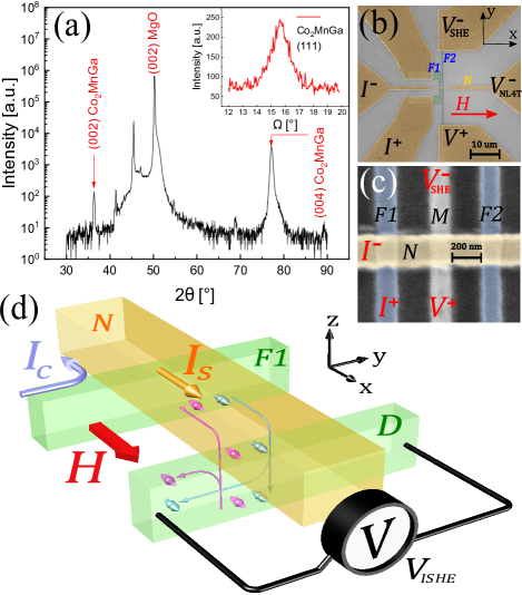
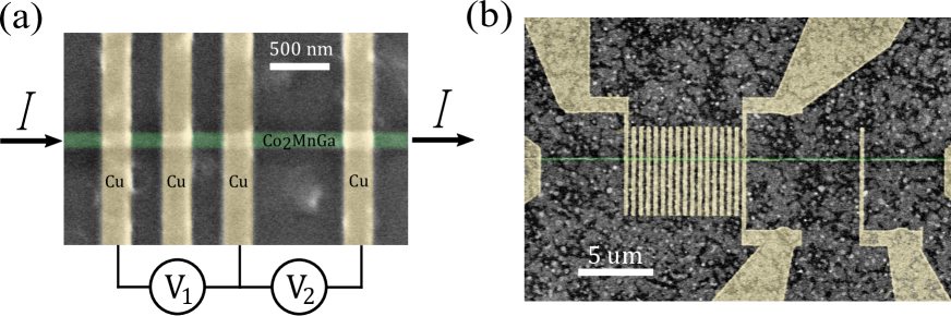
The samples consisted of lateral spin valve (LSV) structures that were fabricated starting from 30-nm-thick films of Co2MnGa epitaxially grown on a (001)-oriented MgO single-crystal substrate. An X-ray diffraction (XRD) -2 (out-of-plane) scan was performed to check the crystal structure in the films. The presence of (002) and (004) peaks of Co2MnGa confirms ordering in the thin films, as shown in Fig. 1(a), meanwhile the presence of (111) peak, as verified by the rocking curve in the inset, confirms the ordering in the samples. The FM electrodes were patterned on the sub-micron scale using conventional electron-beam lithography and Ar ion milling techniques. Two types of devices were fabricated, one with two parallel FM electrodes (Fig. 1(b)) with various channel lengths (edge-to-edge separation) while the other with three electrodes (Fig. 1(c)) with a fixed distance of 600 nm between and and various widths of the middle wire , in order to estimate the spin resistance through the absorption technique [19, 26, 36, 37, 38, 39, 40]. Finally, copper channels perpendicularly connecting the ferromagnetic electrodes, as well as the macroscopic connection pads, were patterned using electron-beam lithography and thermal evaporation techniques. It is worth mentioning that, in order to obtain Ohmic transparent interfaces, a low-acceleration-voltage in-situ Ar ion milling was performed prior to copper deposition. Cu was selected for the non-magnetic channel because of its long spin diffusion length and long spin relaxation time [41], which make it a typical material for nonlocal signal measurements. For reference, devices with the same geometry but with Py ferromagnetic electrodes were fabricated on a thermally oxidized Si substrate. In some of the 2-wire Py devices, an absorption middle wire of Pt was deposited as a reference non-magnetic material, as shown in the scanning electron microscope image of Fig. 1(c). All the transport measurements were performed at room temperature in a commercial physical property measurement system (PPMS) using a DC technique that consists of averaging the absolute value of the voltage measured with positive and negative DC currents, which is equivalent to an AC lock-in technique [42]. Further details of the fabrication procedure, as well as testing of the transparent interfaces and the determination of the spin diffusion length of Co2MnGa are presented in the Supplemental Material in Secs. A, B and C [43].
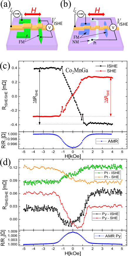
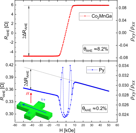
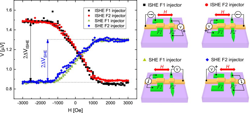
Figure 1(d) shows the scheme of a typical ISHE measurement setup in a LSV. An electric current is injected from the electrode into the left side of the channel (terminals and in Figs. 1(b) and 1(c)) producing spin accumulation at the interface that induces a diffusive pure spin current along the wire [44]. Part of the spin current is then absorbed vertically (negative direction) in a detection electrode ( can be or depending on the device). Since the spin orientation of the conduction electrons is given by the magnetization of , which is fixed by the external magnetic field applied along the channel, a charge current density given by [45] (where is the spin Hall angle and is the spin current density) is generated along the electrode length. In the equilibrium state in open circuit condition, a voltage is generated to suppress the charge current in , measured between terminals and . When the magnetization of the injection electrode is switched, by sweeping the external magnetic field, the sign of the generated voltage is also expected to switch, as it is shown in the ISHE labeled measurements in Fig. 2(c) for Co2MnGa and Fig. 2(d) for Pt and Py as detector electrodes, where . The difference between the saturation values of for positive and negative field is defined as . Reciprocally, if the probe setup is inverted, by exchanging with and with , a charge current along will inject a pure spin current in the interface by means of the (direct) SHE. This spin current will diffuse again across the channel to be detected as a nonlocal voltage between the electrodes and . The SHE setup nonlocal resistance (defined as ) is also shown in the SHE labeled measurements on Fig. 2(c) for Co2MnGa and Fig. 2(d) for Pt and Py, where can be compared with . Note that the magnitudes of ISHE and SHE signals for Co2MnGa are not the same, which is discussed later, and they are substantially large, roughly 20 times greater than for Pt and Py in very similar geometries. Anisotropic magnetoresistance (AMR) curves for the injection electrode are shown to prove that the saturation of the ISHE and SHE signals correspond to the saturation of the magnetization of , where it is worth noting that the AMR of Co2MnGa was found to be negative, as previously reported [46].
| (1) |
where is the spatial average of the absorbed spin current along the direction, is the width of the detector wire and is the shunting factor that takes into account that part of the generated charge current is being shunted by the copper wire. By applying a one dimensional spin diffusion model [47] for transparent interfaces and considering , where the thickness of the detector electrode and its spin diffusion length, can be written as:
| (2) |
for a 2-wire LSV using as detector and
for a 3-wire LSV using as detector, where is the width of wire, is the spin diffusion length of Cu, and are the spin polarizations of the ferromagnetic electrodes and the middle wire material, respectively, and , and are respectively the spin resistances of , (considered to be the same as ) and wires, defined in Ref. [43]. For Eq. Giant spin Hall angle in the Heusler alloy Weyl ferromagnet Co2MnGa it was considered that the middle wire was located at the middle of the gap distance between and electrodes.
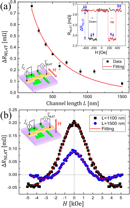
In the case when a FM material is used as a detector electrode, can be written in terms of the conventional nonlocal-4-terminal (NL4T) resistance , which can be measured by connecting terminal instead of in Fig. 1(b) and sweeping the external magnetic field in a direction parallel to the ferromagnetic electrodes length. A typical NL4T signal is shown in the inset of Fig. 3(a), where two different voltage levels are measured depending on whether the relative configuration of the magnetization of the ferromagnetic electrodes is parallel or anti-parallel. The difference between these two voltages, normalized by the injection current, define that is a direct measure of the amount of spin current being absorbed by the detection wire. Then, Eqs. 2 and Giant spin Hall angle in the Heusler alloy Weyl ferromagnet Co2MnGa are simplified into:
| (4) |
where the only unknown spin transport parameter is the spin polarization of the detector electrode . In order to determine , was measured in 2-wire LSVs for several different channel lengths . This gap dependence is shown in Fig.3(a) where the data has been fitted according to the equation [47]:
| (5) |
where the only three unknown parameters are , and , the spin diffusion length of the FM. Since and can not be extracted independently, additional spin absorption measurements were performed to determine self-consistently, yielding nm for Co2MnGa [43]. The spin polarization was also determined via Hanle effect nonlocal measurements, which have the same geometry and sample structure as in NL4T setup except for an out-of-plane external magnetic field instead of in-plane. The data for two different channel lengths is shown in Fig.3(b), where the fitting was performed according to Eqs. (1), (2) and (3) in Ref. [48] for the case of transparent interfaces, to consistently obtain .
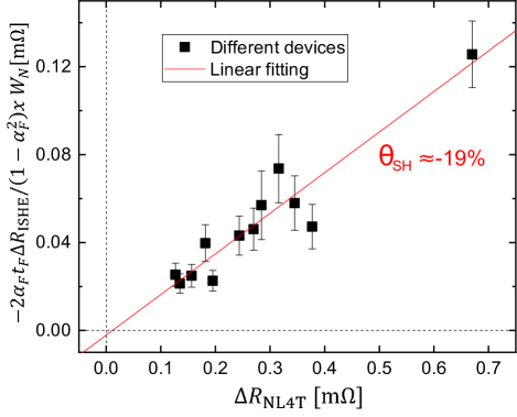
The only unknown parameter left to estimate is the shunting factor , which was determined experimentally with devices specially designed to that end, as detailed in Sec. D of the Supplemental Material [43]. Finally, a linear fitting, shown in Fig. 4, can be performed from the linear relation between and (Eq. 4) to extract a large spin Hall angle , which is simply ascribable to the sizable Berry curvature as aforementioned. This value is significantly larger than conventional FMs such as Py ( [22, 23]), CoFe ( [28]) and CoFeB ( [27]).
According to Onsager’s reciprocal relation [49], the resistance obtained for the SHE setup and ISHE setup should be the same, as it is the case for the Py and Pt control samples in Fig. 2(b). This was first experimentally demonstrated by Kimura et al. [50] for the case of Pt and later verified for many other materials [37, 38, 26]. However, it was not the case for Co2MnGa samples, where ISHE and SHE signals are clearly different, as shown in Fig. 2(c). It is important to note that there is no effect of the geometry of the devices on whether the reciprocity holds or not, as verified in the control experiments detailed in Sec. H of Supplemental Material [43].
While the origin of the reciprocity is well understood for nonmagnetic materials [51], it is still unclear why the relation should hold in FM systems, since there is a breaking of the time-reversal symmetry. Furthermore, recent advances in the field suggest that nonreciprocal transport can exist in chiral materials such as Weyl semimetals [52].
In case of Co2MnGa, the non-reciprocity could be explained through a phenomenological picture of the Hall phenomena, by introducing the spin-dependent spin Hall angles , and the polarization of the spin Hall angle through the relations and , where is the spin-dependent Hall conductivity and is the spin-dependent normal conductivity [34, 26]. In the conventional case where is assumed to be zero, the anomalous Hall angle is expected to be related to via the spin polarization in the form [22], as demonstrated for Py [26]. However, the value of observed for Co2MnGa and Py have the same sign, as shown in Fig. 5, while exhibits different signs in both materials, as shown in Figs. 2(c) and 2(d). If a finite is considered, the relation should hold [43], indicating should be negative and . In addition, the relation between ISHE and SHE resistances obtained with the one dimensional spin diffusion model [43]:
| (6) |
indicates , which is clear in Fig. 2(c). Refer to Sec. G of Supplemental Material for a more detailed description of this spin-dependent spin Hall angle-based approach [43].
In conclusion, a direct and effective method to determine the spin Hall angle in ferromagnets was introduced, to obtain a significantly large value of for Heusler alloy Co2MnGa, a Weyl semimetal. Combined with the ability to control the intensity of ISHE through the magnetization direction and the high resistivity of the compound [43], this result situates Co2MnGa as a robust platform for detection and generation of spin currents in future spintronic devices. Furthermore, a lack of reciprocity between ISHE and SHE resistances was observed and attributed to a negative polarization of the spin Hall angle.
This research was supported in part by a Grant-in-Aid for Scientific Research from the Ministry of Education, Culture, Sports, Science and Technology (MEXT) of Japan (Innovative Area “Nano Spin Conversion Science” KAKENHI No. 26103003), Grant-in-Aid for Young Scientists (A) No. 16H06089 and Grant-in-Aid for Scientific Research (S) ”Semiconductor Spincurrentronics” No. 16H06330. L. L. acknowledges support from MEXT doctoral scholarship. S. G. acknowledges financial support from the New Zealand Science for Technological Innovation National Science Challenge. The MacDiarmid Institute is supported under the New Zealand Centres of Research Excellence Programme.
References
- Lv et al. [2015] B. Q. Lv, H. M. Weng, B. B. Fu, X. P. Wang, H. Miao, J. Ma, P. Richard, X. C. Huang, L. X. Zhao, G. F. Chen, Z. Fang, X. Dai, T. Qian, and H. Ding, Experimental discovery of Weyl semimetal TaAs, Phys. Rev. X 5, 031013 (2015).
- Nielsen and Ninomiya [1983] H. Nielsen and M. Ninomiya, The Adler-Bell-Jackiw anomaly and Weyl fermions in a crystal, Physics Letters B 130, 389 (1983).
- Yang et al. [2017] H. Yang, Y. Sun, Y. Zhang, W.-J. Shi, S. S. Parkin, and B. Yan, Topological Weyl semimetals in the chiral antiferromagnetic materials Mn3Ge and Mn3Sn, New J. Phys. 19, 015008 (2017).
- Sakai et al. [2018] A. Sakai, Y. P. Mizuta, A. A. Nugroho, R. Sihombing, T. Koretsune, M.-T. Suzuki, N. Takemori, R. Ishii, D. Nishio-Hamane, R. Arita, et al., Giant anomalous nernst effect and quantum-critical scaling in a ferromagnetic semimetal, Nature Physics 14, 1119 (2018).
- Chang et al. [2017] G. Chang, S. Y. Xu, X. Zhou, S. M. Huang, B. Singh, B. Wang, I. Belopolski, J. Yin, S. Zhang, A. Bansil, H. Lin, and M. Z. Hasan, Topological Hopf and chain link semimetal states and their application to Co2MnGa, Phys. Rev. Lett. 119, 156401 (2017).
- Matsuda et al. [2020] T. Matsuda, N. Kanda, T. Higo, N. Armitage, S. Nakatsuji, and R. Matsunaga, Room-temperature terahertz anomalous Hall effect in Weyl antiferromagnet Mn3Sn thin films, Nat Commun 11, 909 (2020).
- Ludbrook et al. [2017] B. M. Ludbrook, B. J. Ruck, and S. Granville, Perpendicular magnetic anisotropy in Co2MnGa and its anomalous Hall effect, Appl. Phys. Lett. 110, 062408 (2017).
- Nakatsuji et al. [2015] S. Nakatsuji, N. Kiyohara, and T. Higo, Large anomalous Hall effect in a non-collinear antiferromagnet at room temperature, Nature 527, 212 (2015).
- Kimata et al. [2019] M. Kimata, H. Chen, K. Kondou, S. Sugimoto, P. K. Muduli, M. Ikhlas, Y. Omori, T. Tomita, A. H. MacDonald, S. Nakatsuji, et al., Magnetic and magnetic inverse spin Hall effects in a non-collinear antiferromagnet, Nature 565, 627 (2019).
- Reichlova et al. [2018] H. Reichlova, R. Schlitz, S. Beckert, P. Swekis, A. Markou, Y.-C. Chen, D. Kriegner, S. Fabretti, G. Hyeon Park, A. Niemann, et al., Large anomalous nernst effect in thin films of the weyl semimetal co2mnga, Applied Physics Letters 113, 212405 (2018).
- Coey and Venkatesan [2002] J. M. D. Coey and M. Venkatesan, Half-metallic ferromagnetism: Example of CrO2 (invited), J. Appl. Phys. 91, 8345 (2002).
- Felser and Fecher [2013] C. Felser and G. H. Fecher, Spintronics: from materials to devices (Springer Science & Business Media, 2013).
- Kimura et al. [2012] T. Kimura, N. Hashimoto, S.Yamada, M. Miyao, and K. Hamaya, Room-temperature generation of giant pure spin currents using epitaxial Co2FeSi spin injectors, NPG Asia Materials 4, e9 (2012).
- Shirotori et al. [2015] S. Shirotori, S. Hashimoto, M. Takagishi, Y. Kamiguchi, and H. Iwasaki, All-metallic nonlocal spin valves using polycrystalline Co2 (FeMn) Si Heusler alloy with large output, Appl. Phys Express 8, 023103 (2015).
- Sinova et al. [2015] J. Sinova, S. O. Valenzuela, J. Wunderlich, C. H. Back, and T. Jungwirth, Spin hall effects, Rev. Mod. Phys. 87, 1213 (2015).
- Saitoh et al. [2006] E. Saitoh, M. Ueda, and H. Miyajima, High spin polarization of the anomalous hall current in co-based heusler compounds, Appl. Phys. Lett. 88, 182509 (2006).
- Wang et al. [2014] H. L. Wang, C. H. Du, Y. Pu, R. Adur, P. C. Hammel, and F. Y. Yang, Scaling of spin hall angle in 3d, 4d, and 5d metals from /metal spin pumping, Phys. Rev. Lett. 112, 197201 (2014).
- Tao et al. [2018] X. Tao, Q. Liu, B. Miao, R. Yu, Z. Feng, L. Sun, B. You, J. Du, K. Chen, S. Zhang, et al., Self-consistent determination of spin hall angle and spin diffusion length in pt and pd: The role of the interface spin loss, Science advances 4, eaat1670 (2018).
- Morota et al. [2011] M. Morota, Y. Niimi, K. Ohnishi, D. H. Wei, T. Tanaka, H. Kontani, T. Kimura, and Y. Otani, Indication of intrinsic spin hall effect in and transition metals, Phys. Rev. B 83, 174405 (2011).
- Mosendz et al. [2010] O. Mosendz, J. E. Pearson, F. Y. Fradin, G. E. W. Bauer, S. D. Bader, and A. Hoffmann, Quantifying spin hall angles from spin pumping: Experiments and theory, Phys. Rev. Lett. 104, 046601 (2010).
- Taniguchi et al. [2015] T. Taniguchi, J. Grollier, and M. D. Stiles, Spin-transfer torques generated by the anomalous hall effect and anisotropic magnetoresistance, Phys. Rev. Applied 3, 044001 (2015).
- Tsukahara et al. [2014] A. Tsukahara, Y. Ando, Y. Kitamura, H. Emoto, E. Shikoh, M. P. Delmo, T. Shinjo, and M. Shiraishi, Self-induced inverse spin hall effect in permalloy at room temperature, Phys. Rev. B 89, 235317 (2014).
- Miao et al. [2013] B. F. Miao, S. Y. Huang, D. Qu, and C. L. Chien, Inverse spin hall effect in a ferromagnetic metal, Phys. Rev. Lett. 111, 066602 (2013).
- Seki et al. [2015] T. Seki, K.-i. Uchida, T. Kikkawa, Z. Qiu, E. Saitoh, and K. Takanashi, Observation of inverse spin hall effect in ferromagnetic fept alloys using spin seebeck effect, Applied Physics Letters 107, 092401 (2015).
- Seki et al. [2019] T. Seki, S. Iihama, T. Taniguchi, and K. Takanashi, Large spin anomalous Hall effect in -FePt: Symmetry and magnetization switching, Phys. Rev. B 100, 144427 (2019).
- Omori et al. [2019] Y. Omori, E. Sagasta, Y. Niimi, M. Gradhand, L. E. Hueso, F. Casanova, and Y. Otani, Relation between spin hall effect and anomalous hall effect in ferromagnetic metals, Phys. Rev. B 99, 014403 (2019).
- Iihama et al. [2018] S. Iihama, T. Taniguchi, K. Yakushiji, A. Fukushima, Y. Shiota, S. Tsunegi, R. Hiramatsu, S. Yuasa, Y. Suzuki, and H. Kubota, Spin-transfer torque induced by the spin anomalous hall effect, Nature Electronics 1, 120 (2018).
- Wimmer et al. [2019] T. Wimmer, B. Coester, S. Geprägs, R. Gross, S. T. Goennenwein, H. Huebl, and M. Althammer, Anomalous spin hall angle of a metallic ferromagnet determined by a multiterminal spin injection/detection device, Applied Physics Letters 115, 092404 (2019).
- Zimmermann et al. [2014] B. Zimmermann, K. Chadova, D. Ködderitzsch, S. Blügel, H. Ebert, D. V. Fedorov, N. H. Long, P. Mavropoulos, I. Mertig, Y. Mokrousov, and M. Gradhand, Skew scattering in dilute ferromagnetic alloys, Phys. Rev. B 90, 220403 (2014).
- Hoffmann [2013] A. Hoffmann, Spin hall effects in metals, IEEE Transactions on Magnetics 49, 5172 (2013).
- Markou et al. [2019] A. Markou, D. Kriegner, J. Gayles, L. Zhang, Y.-C. Chen, B. Ernst, Y.-H. Lai, W. Schnelle, Y.-H. Chu, Y. Sun, et al., Thickness dependence of the anomalous hall effect in thin films of the topological semimetal co 2 mnga, Physical Review B 100, 054422 (2019).
- Sun et al. [2016] Y. Sun, Y. Zhang, C. Felser, and B. Yan, Strong intrinsic spin hall effect in the taas family of weyl semimetals, Phys. Rev. Lett. 117, 146403 (2016).
- Kolbe et al. [2012] M. Kolbe, S. Chadov, E. A. Jorge, G. Schönhense, C. Felser, H. J. Elmers, M. Kläui, and M. Jourdan, Test of band structure calculations for Heusler compounds by spin-resolved photoemission spectroscopy, Phys. Rev. B 86, 024422 (2012).
- Tung and Guo [2013] J.-C. Tung and G.-Y. Guo, High spin polarization of the anomalous hall current in co-based heusler compounds, New Journal of Physics 15, 033014 (2013).
- Holmes and Pepper [2002] S. Holmes and M. Pepper, Magnetic and electrical properties of co 2 mnga grown on gaas (001), Applied physics letters 81, 1651 (2002).
- Laczkowski et al. [2015] P. Laczkowski, H. Jaffrès, W. Savero-Torres, J.-C. Rojas-Sánchez, Y. Fu, N. Reyren, C. Deranlot, L. Notin, C. Beigné, J.-P. Attané, et al., Evaluation of spin diffusion length of auw alloys using spin absorption experiments in the limit of large spin-orbit interactions, Physical Review B 92, 214405 (2015).
- Niimi et al. [2011] Y. Niimi, M. Morota, D. H. Wei, C. Deranlot, M. Basletic, A. Hamzic, A. Fert, and Y. Otani, Extrinsic spin hall effect induced by iridium impurities in copper, Phys. Rev. Lett. 106, 126601 (2011).
- Niimi et al. [2012] Y. Niimi, Y. Kawanishi, D. H. Wei, C. Deranlot, H. X. Yang, M. Chshiev, T. Valet, A. Fert, and Y. Otani, Giant spin hall effect induced by skew scattering from bismuth impurities inside thin film cubi alloys, Phys. Rev. Lett. 109, 156602 (2012).
- Sagasta et al. [2017] E. Sagasta, Y. Omori, M. Isasa, Y. Otani, L. E. Hueso, and F. Casanova, Spin diffusion length of permalloy using spin absorption in lateral spin valves, Applied Physics Letters 111, 082407 (2017).
- Zahnd et al. [2018] G. Zahnd, L. Vila, V. Pham, M. Cosset-Cheneau, W. Lim, A. Brenac, P. Laczkowski, A. Marty, and J. Attané, Spin diffusion length and polarization of ferromagnetic metals measured by the spin-absorption technique in lateral spin valves, Physical Review B 98, 174414 (2018).
- Jedema et al. [2003] F. J. Jedema, M. S. Nijboer, A. T. Filip, and B. J. van Wees, Spin injection and spin accumulation in all-metal mesoscopic spin valves, Phys. Rev. B 67, 085319 (2003).
- Casanova et al. [2009] F. Casanova, A. Sharoni, M. Erekhinsky, and I. K. Schuller, Control of spin injection by direct current in lateral spin valves, Phys. Rev. B 79, 184415 (2009).
- [43] See Supplemental Material at [url will be inserted by publisher] for details on sample preparation, determination of relevant parameters, characterization of magnetic electrodes, angle dependence of ISHE signal and discussion on the validity of reciprocal relations, .
- Valenzuela [2009] S. O. Valenzuela, Nonlocal electronic spin detection, spin accumulation and the spin Hall effect, International Journal of Modern Physics B 23, 2413 (2009).
- Takahashi and Maekawa [2008] S. Takahashi and S. Maekawa, Spin current, spin accumulation and spin hall effect, Science and Technology of Advanced Materials 9, 014105 (2008), pMID: 27877931, https://doi.org/10.1088/1468-6996/9/1/014105 .
- Sato et al. [2018] T. Sato, S. Kokado, S. Kosaka, T. Ishikawa, T. Ogawa, and M. Tsunoda, Large negative anisotropic magnetoresistance in Co2MnGa Heusler alloy epitaxial thin films, Appl. Phys. Lett. 113, 112407 (2018).
- Takahashi and Maekawa [2003] S. Takahashi and S. Maekawa, Spin injection and detection in magnetic nanostructures, Phys. Rev. B 67, 052409 (2003).
- Rojas Sánchez et al. [2013] J.-C. Rojas Sánchez, P. Laczkowski, W. Savero Torres, M. Cubukcu, V. Nguyen, L. Notin, C. Beigné, C. Vergnaud, A. Marty, M. Jamet, et al., In-plane and out-of-plane spin precession in lateral spin-valves, Applied Physics Letters 102, 132408 (2013).
- Onsager [1931] L. Onsager, Reciprocal relations in irreversible processes. II., Phys. Rev. 38, 2265 (1931).
- Kimura et al. [2007] T. Kimura, Y. Otani, T. Sato, S. Takahashi, and S. Maekawa, Room-temperature reversible spin Hall effect, Phys Rev Lett 98, 156601 (2007).
- Jacquod et al. [2012] P. Jacquod, R. S. Whitney, J. Meair, and M. Büttiker, Onsager relations in coupled electric, thermoelectric, and spin transport: The tenfold way, Phys. Rev. B 86, 155118 (2012).
- Tokura and Nagaosa [2018] Y. Tokura and N. Nagaosa, Nonreciprocal responses from non-centrosymmetric quantum materials, Nat Commun 9, 3740 (2018).
- Hu and Kimura [2014] S. Hu and T. Kimura, Significant modulation of electrical spin accumulation by efficient thermal spin injection, Physical Review B 90, 134412 (2014).
- Pedersen and Vernon [1967] R. J. Pedersen and F. L. Vernon, Effect of film resistance on low-impedance tunneling measurements, Appl. Phys. Lett. 10, 29 (1967).
- Fenn et al. [1998] M. Fenn, G. Akuetey, and P. E. Donovan, Electrical resistivity of Cu and Nb thin films, J. Phys.: Condens. Matter 10, 1707 (1998).
- Damsgaard et al. [2009] C. D. Damsgaard, M. C. Hickey, S. N. Holmes, R. Feidenhans’l, S. O. Mariager, C. S. Jacobsen, and J. B. Hansen, Interfacial, electrical and spin-injection properties of epitaxial CoMnGa grown on GaAs(100), J. Appl. Phys. 105, 124502 (2009).
- Hamaya et al. [2012] K. Hamaya, N. Hashimoto, S. Oki, S. Yamada, M. Miyao, and T. Kimura, Estimation of the spin polarization for Heusler-compound thin films by means of nonlocal spin-valve measurements: Comparison of Co2FeSi and Fe3Si, Phys. Rev. B 85, 100404 (2012).
- Zhang et al. [2011] H. Zhang, F. Freimuth, S. Blügel, Y. Mokrousov, and I. Souza, Role of spin-flip transitions in the anomalous hall effect of fept alloy, Phys. Rev. Lett. 106, 117202 (2011).
Supplemental Materials: Giant spin Hall angle in the Heusler alloy Weyl ferromagnet Co2MnGa
.1 Sample preparation
Co2MnGa films were grown using an ultra-high vacuum DC magnetron sputtering system with a base pressure of 2 10-8 Torr at a temperature of 400 ∘C, with a subsequent annealing at 550 ∘C during 60 minutes. Since the growth of the films and the microfabrication process were made at different places, a 40 nm-thick copper capping layer was grown on top of the Heusler alloy layer without breaking the vacuum but after cooling to room temperature. This capping layer was removed right before making the lateral spin valves. Injection and detection ferromagnetic electrodes ( and in Fig. 1(b)) width varied between 150 nm and 200 nm. Different switching fields were achieved by changing the shape of the electrodes, favoring the domain rotation with a flag structure in case of , so the same width (at the interfaces with the nonmagnetic channel) could be used for both electrodes in a same device. The edge-to-edge separation, also known as channel length , between the ferromagnetic electrodes varied from 150 nm to 1500 nm. In case of middle wire devices (Fig. 1(c) on main text) the width of the middle wire was between 60 nm and 150 nm, while was fixed at 600 nm. For Cu channels, a width of 200 nm and a thickness of 100 nm were used.
.2 Interface resistance measurement
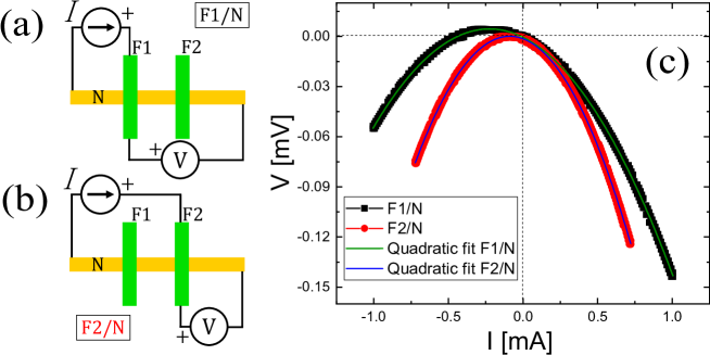
Obtaining transparent interfaces is important to reliably extract spin transport parameters such as spin polarization and spin diffusion length from the nonlocal resistance measurements. To this end, a 500V acceleration voltage Ar ion milling step is performed in-situ prior to Cu deposition. The interface resistance was measured at every device using the cross configuration shown in Fig. S1, where typical I-V curves for the interfaces of and with are shown. A significant quadratic contribution was observed, attributed to thermally originated electromotive forces due to the temperature gradient in the interface [53]. Apart from that, a clear negative linear contribution of around -0.05 is obtained from the polynomial fitting, as expected for a transparent interface. This measured negative resistance is an artifact that occurs when the resistance of the metal electrodes along the junction is similar or higher than the interface resistance of the junction itself [54]. To estimate the real magnitude of the interface resistances, a finite element method simulation was performed, where, for a fixed current, the interface resistance was systematically changed until the voltage at the measurement points matched the experimental result. Calculation yield to a product of the interface resistance with the junction area fm2 in all reported cases.
.3 Determination of the spin diffusion length of absorption wire
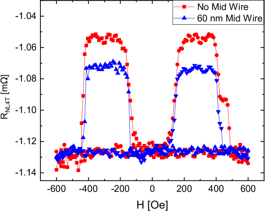
To estimate the spin diffusion length of Co2MnGa, the spin absorption technique was used. The experiment setup is equivalent to that for the nonlocal 4 terminal (NL4T) resistance measurement, where is obtained, as detailed in the main text. Electrodes and were used as injector and detector, respectively (see Fig. 1(c)), in devices with different widths of the middle wire , obtaining . Additionally, devices with the same separation between and but no middle wire were used as reference samples, obtaining . The signal is expected to decrease with the presence of the middle wire, since part of the spin current is absorbed there. The quotient between these two signals can be calculated using the 1D spin diffusion model, leading to:
| (S1) |
where it was assumed and the position of the middle wire , in a point contact model, is right at the middle of the gap. The spin resistance is defined as , where , , and denotes the electrical resistivity, the spin diffusion length, the spin polarization and the effective cross sectional area, respectively, for an specific “X” material. A typical measurement is shown in Fig. S2, where is the same material as and , and thus it has the same spin polarization and spin diffusion length . In order to determine , equation S1 should be used together with Eq. (5) and the data of Fig. 3 of main text, where the dependence of for devices with no middle wire was studied. Unknown parameters are , and , since the resistivities were determined with a 4-probe method obtaining cm and cm, which agree with reports in the literature [55, 56], and the effective cross sectional areas depend on the sample geometry that was determined with Atomic Force Microscopy technique and SEM imaging. By iterating between equations S1 and 5, the three unknown parameters where extracted consistently obtaining , nm and nm. This latter value is in the order of the reported spin diffusion lengths for similar Heusler compounds [57].
.4 Determination of the shunting factor
In the ISHE setup, a spin current is absorbed by the ferromagnet F2 from the nonmagnetic channel N. Since is, as previously calculated, in the order of a few nm, the spin to charge conversion will occur mostly very close to the N/F2 interface. Therefore, it is expected that some of the ISHE-generated charge current at the will shunt through the much more conductive Cu channel. This will produce a decrease of the generated voltage, in a fraction () of the total expected voltage if no shunting existed. This can also be understood as being the fraction of the total current that will go through the FM. In a similar way, in the SHE setup, a charge current is injected at the FM, and it is also expected that, at the N/F2 interface, part of the current will shunt through the Cu wire meanwhile a fraction will remain in the FM. This will produce a decrease of the voltage drop across the FM wire, compared to when no shunting happens. In order to estimate the magnitude of this effect, that is quite critical for the spin Hall angle calculation, multi-terminal devices such as those of Fig. S3 were fabricated. The experiment is described in Fig. S3(a), where a charge current is injected through the Co2MnGa electrode terminals. The voltage is expected to be less than due to the additional shunting through the Cu middle wire, following the relation:
| (S2) |
where is the width of the Cu wires and is the separation between adjacent Cu wires.
Since there was a significant dispersion on the values extracted by this method, due to process variations, devices with several shunting middle wires were designed, as shown in Fig. S3(b), in order to average the shunting effect through the multiple wires. The widths of the Cu and Co2MnGa wires were selected to replicate those of the lateral spin valves used for the SHE measurements. Finally, the reciprocal of the shunting factor was found to be .
.5 Angular dependence of inverse spin Hall effect voltage
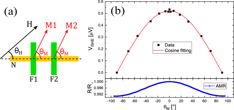
In order to prove that the magnitude of the inverse spin Hall effect signals can be controlled through the magnetization orientation, the dependence of the ISHE voltage with the angle of the magnetization was studied. To this end, the angle of the external magnetic field was varied, as shown in Fig. S4(a). Since a magnetic anisotropy exists due to the electrode shape, in principle will not coincide with the angle of the magnetization . AMR measurements for and confirmed that both magnetizations and remain approximately parallel to each other as they rotates due to the rotation of the external field. Since the maximum value used for the sweep of the magnetic field in the ISHE measurements (4 kOe) was not enough to assure and were parallel, a correction was made to convert to the real . To this end, the AMR curve of was measured for a sufficiently high magnetic field of 60 kOe so , shown in Fig. S4(b). The magnetic field angle dependence of the resistance was also obtained with a field of 4kOe to determine by matching the resistances with the high field curve. The ISHE voltage, for a same injection current of 1 mA, as a function of is shown in Fig. S4(b), where the expected cosine behavior confirms the signal magnitude is being controlled through the magnetization direction.
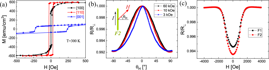
.6 Characterization of ferromagnetic electrodes
Before patterning of ferromagnetic electrodes, the magnetization of Co2MnGa thin films was measured using a SQUID magnetometer along the crystalline directions [100], [110] and [001]. As shown in the XRD pattern of Fig. 1(a) in the main text, the [001] axis is out of the substrate plane, and therefore the saturation occurs at a high magnetic field of 10 kOe (not shown) due to shape anisotropy. Concerning the in-plane directions, it was found the existence of magneto-crystalline anisotropy with easy axis along the [110] direction (Fig. S5(a)), which was verified to be parallel to the substrate sides. However, after the patterning of FM electrodes, the shape anisotropy of these thin wires was found to be much more significant than the original magneto-crystalline anisotropy of the films. In Fig. S5(b), it can be seen that for a high enough magnetic field of 60 kOe, magnetization and magnetic field are parallel, showing the AMR a behavior. However, for a smaller magnetic field of 3 kOe, it is clear how the shape anisotropy makes the magnetization to be closer to the direction parallel to electrode length. When the in-plane magnetic field direction is fixed perpendicular to ferromagnetic electrodes length (), this is, the same condition as in SHE and ISHE measurements, it can be seen that the AMR of both F1 and F2 electrodes saturates for a field around 2000 Oe. The relative amplitude of AMR is smaller in F1 electrode, but this is due to its different shape, as shown in Fig. 1(b) in the main text, where part of the electric current is not parallel to the electrode length. However, the AMR curves for both F1 and F2 are the same except for a scale factor. The conclusion is that the magnetization of both ferromagnetic electrodes rotate coherently when the magnetic field is swept, probably because F1 and F2 have the same width.
.7 On the validity of Onsager’s reciprocal relation
In order to explain the origin of the breaking of reciprocity observed in the ISHE and SHE experiments on Co2MnGa, a phenomenological picture is presented. Assuming the validity of the two channel model, the total charge current density is decomposed into the spin components as , meanwhile the spin current (with charge current units) is defined as . The spin Hall effect-generated currents and can be described for each spin-component of the current as and , where and are the spin-dependent spin Hall angles, defined in terms of the spin-dependent Hall and normal conductivities. The spin Hall angle is defined as and the polarization of the spin Hall angle is introduced as .
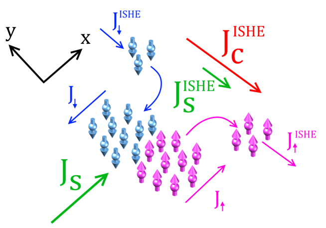
The ISHE case is shown schematically in Fig. S6, where the direction of electron motion is that of the charge flow, for simplicity. In this kind of experiment, the source is a diffusive pure spin current that is absorbed by the FM material, so along the direction. Then, the ISHE-generated charge current along direction is , meanwhile the generated spin current is . Since the measured ISHE voltage is proportional to , this method allows to extract regardless of the value of .
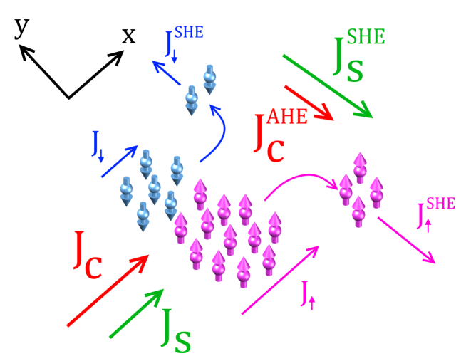
In contrast, the SHE case, shown schematically in Fig. S7, is essentially different since the source is not a pure charge current (as it would be in a nonmagnetic material) but a spin polarized charge current, because of the spin polarization of the FM, defined as . Therefore the spin components of the current along direction are and . Then, the SHE-generated charge current along the direction, also known as anomalous Hall effect current, is and the anomalous spin Hall angle can be expressed as , where it is clear that and may have different sign if is negative. In Fig. S7 diagram, it would mean a larger number of spin-down (blue) electrons will scatter to left. If this number is high enough, the direction of can be inverted while the direction of remains the same. On the other hand, the SHE-generated spin current is , where a non-zero would imply an asymmetry with respect to the ISHE case.
To calculate the SHE nonlocal resistance measured in the SHE setup for a 2-wire device, as described in the main text, a similar derivation as used for the NL4T resistance (Eq. 5 on main text) can be done. While the detection mechanism is essentially the same, the spin injection is different in SHE and NL4T cases. In electrical spin injection, the source of spin accumulation is an electric-field-driven drift spin current in the ferromagnet, while in SHE-driven spin injection, the source of spin accumulation is also a drift spin current but generated via the SHE. Then, the boundary conditions are modified at the injection interface. This imply that one of the factors in Eq. 5 of main text ends up being replaced by , being the final expression for :
| (S3) |
By comparing Eq. S3 with the expression for of Eq. 2 in main text, the Eq. 6 of the main manuscript is obtained, where the lack of reciprocity is exposed. This model consistently explains that a different sign for and implies the SHE resistance is reduced with respect to the ISHE resistance, which agrees with the experimental results in Fig. 2(c) of main text.
It should be pointed out that the above decomposition of the spin Hall effect in two spin-conserving effects for up-spin and down-spin carriers is not a fully precise picture, since it is known the spin-orbit coupling generally mixes spin-up and spin-down states through spin flip processes. However, for light elements such as 3d transition metals, the perfect two-current model is expected to be still reasonably valid [58].
.8 Checking the influence of sample geometry on the reciprocity of transport signals
As shown in the SEM image of Fig. 1(b) of the main text, as well as in the schematics of Fig. S8, the ferromagnetic electrodes F1 and F2 have different shape. This design is in order to achieve different switching fields when the magnetic field is parallel to the electrode length in the nonlocal-4-terminal setup. Therefore, F1 and F2 are not equivalent, and the measured signals when using F1 as injector and F2 as detector and vice versa were checked, both for ISHE and SHE setups, as shown in Fig. S8. It can be seen that, regardless of which electrodes are used for injection and detection, the measured amplitudes are the same, either for the SHE or the ISHE setup. Thus, any possible influence of the non-symmetrical geometry on the non-reciprocity is discarded. At the same time, the breaking of the reciprocity, this is, different amplitudes for and (for the same injection current), were consistently observed again in random device tests made for this check.