Ferromagnetic helical nodal line and Kane-Mele spin-orbit coupling in kagome metal \ceFe3Sn2
Abstract
The two-dimensional kagome lattice hosts Dirac fermions at its Brillouin zone corners K and K’, analogous to the honeycomb lattice. In the density functional theory electronic structure of ferromagnetic kagome metal \ceFe3Sn2, without spin-orbit coupling we identify two energetically split helical nodal lines winding along in the vicinity of K and K’ resulting from the trigonal stacking of the kagome layers. We find that hopping across A-A stacking introduces a layer splitting in energy while that across A-B stacking controls the momentum space amplitude of the helical nodal lines. The effect of spin-orbit coupling is found to resemble that of a Kane-Mele term, where the nodal lines can either be fully gapped to quasi-two-dimensional massive Dirac fermions, or remain gapless at discrete Weyl points depending on the ferromagnetic moment orientation. Aside from numerically establishing \ceFe3Sn2 as a model Dirac kagome metal, our results provide insights into materials design of topological phases from the lattice point of view, where paradigmatic low dimensional lattice models often find realizations in crystalline materials with three-dimensional stacking.
.1 Introduction
Topological nodal lines are one-dimensional manifolds of band degeneracies in momentum space first introduced conceptually by Burkov et al. in 2011 as a higher dimensional generalization of point-like band touching [1]. Such line nodes have in recent years found realizations in various forms in crystalline materials, including infinite lines extending over Brillouin zones [2], closed loops [3], along with intricate three dimensional networks of chains, knots, and nexuses [4, 5, 6, 7, 8, 9]. Interest in electronic line nodes are partly motivated by the peculiar emergent condensed matter quasiparticles they support, which do not possess fundamental particle analogues [4]. Furthermore, due to bulk-boundary correspondence, nodal lines in three dimensional bulk materials generate surface states enclosed in their surface projection; these signature surface states under certain circumstances bear little momentum-space dispersion over a finite region in the surface Brillouin zone [1] and are therefore termed “drumhead surface states”. The enhanced density of states of drumhead surface states is expected to provide a route towards high-temperature correlated phases including ferromagnetism and superconductivity [10].
Viewed in the context of band topology, nodal lines in three-dimensional materials are necessarily protected by symmetries [8] and therefore serve as progenitors for a large number of distinct topological electronic states when the corresponding symmetry is relieved. For instance, broken mirror symmetry is suggested to separate intersecting nodal lines and serve to manipulate an embedded non-Abelian topology [7]. The prototype inversion symmetry- breaking Weyl semimetal TaAs [11] and time-reversal symmetry breaking Weyl semimetal \ceCo3Sn2S2 [12] can both be viewed as generated by adding spin-orbit coupling–which breaks the SU(2) spin-rotation symmetry–to nodal loops on mirror planes. In addition, nodal lines in certain cases can be fully gapped and further give rise to topological insulating phases [9]. From the materials perspective, elucidating mechanisms of generating topological nodal lines and their interplay with different types of symmetries–including crystallographic symmetries, spin-rotation symmetry, and time-reversal symmetry–are expected to afford key clues in discovering novel topological electronic states and allow the study of emergent electromagnetic responses in such systems.
Motivated by the experimental discovery of quasi-two-dimensional Dirac electronic dispersions in the vicinity of the Fermi level in the ferromagnetic kagome metal \ceFe3Sn2 [13], we here examine the density functional theory (DFT) electronic structure of the system in the context of three-dimensional (3D) topological nodal lines. In the following, we use the convention of Dirac fermions referring to linearly dispersing two-dimensional bands as in topological insulator surface states [14] or the two-dimensional graphene [15] and kagome models [16]. For the case of the considered 3D material, this convention includes crossing states with linear dispersion in two dimensions and preserved degeneracy in the third dimension (nodal lines), regardless of their degeneracy. This should be contrasted with the convention associated with the four-fold degeneracy of 3D Dirac semimetals that are described by the 3D Dirac equation [17]. The two-dimensional kagome lattice is composed of corner-shared triangles (see Fig. 1(a)) and is known theoretically to host Dirac fermions at its Brillouin zone corners K and K’ in the electronic spectrum as illustrated in Fig. 1(b) – analogous to the honeycomb lattice [16]. In contrast to the honeycomb lattice whose experimental realization primarily falls into -electron materials such as graphene and other main group X-enes [18], the kagome lattice has found extensive presence in a class of transition metal intermetallic compounds termed “kagome metals”, where the kagome bands are composed by electrons [13, 22, 12, 23, 20, 19, 21, 24]. As these compounds crystallize in three-dimensional structures, a natural question is how the notion of the point nodes in the two-dimensional limit can be extended to the third dimension. The subject of this study – binary ferromagnetic kagome metal \ceFe3Sn2 has been experimentally identified as host of bulk quasi-two-dimensional Dirac fermions in transport and photoemission spectroscopy [13], as well as in de Haas-van Alphen quantum oscillations [25] and optical conductivity [26]. Scanning tunneling microscopy has revealed a strongly anisotropic response of the electronic structure of \ceFe3Sn2 due to spin-orbit coupling [27], and more recently a large number of Weyl points are also proposed to be present in the system [28]. In view of the successful application of DFT to related topological kagome metals [22, 20], a comprehensive DFT study of the electronic structure of \ceFe3Sn2 is expected to address the nature of its electronic topology and offer insights into the origin of experimentally observed Dirac fermions.
In this study we first identify two sets of ferromagnetic helical nodal lines in \ceFe3Sn2 near K and K’ of the hexagonal Brillouin zone in the limit of vanishing spin-orbit coupling. We also found that with the introduction of spin-orbit coupling, these nodal lines are gapped into a three-dimensional quantum anomalous Hall insulating phase with out-of-plane ferromagnetic moments while with in-plane moments, point Weyl nodes remain gapless along the helices. The helical nodal lines are found to originate from the rhombohedral stacking of the bilayer kagome lattices and also subject to a layer splitting between upper and lower branches. We propose that these ferromagnetic helical nodal lines are the key to describe the topological electronic structure in \ceFe3Sn2 and insights obtained herein can be broadly applied to various three dimensional constructions of two-dimensional lattice models.
.2 Ferromagnetic helical nodal line in \ceFe3Sn2
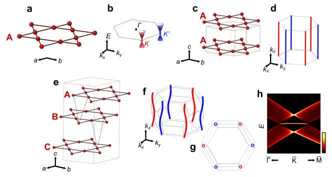
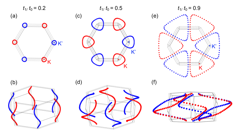
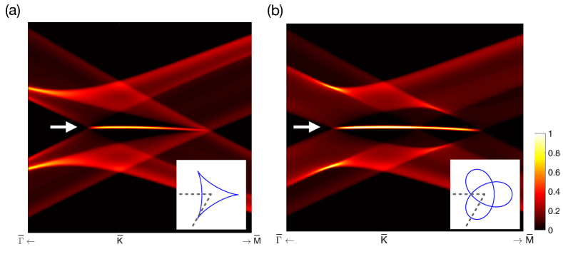
We start from the two-dimensional (2D) nearest neighbor tight-binding model of the kagome lattice as shown in Fig. 1(a), where we highlight the Dirac fermions located at and , with opposite chirality shown in red and blue, respectively in Fig. 1(b). In Fig. 1(c-g) we illustrate the effects of three-dimensional (3D) stacking with a moderate interplane hopping on these Dirac fermions. For clarity in Fig. 1(c,e) we introduce only the in-plane nearest neighbor hopping (solid lines) and the nearest out-of-plane hopping (dashed lines). The location of band crossing points in the 3D Brillouin zone (BZ) with are shown in Fig. 1(d,f,g). In the simpler A-A stacking the hopping along the direction extends the Dirac points at and to vertical nodal lines along the () directions (Fig. 1(d)). A-B-C stacking instead results in helical nodal lines where at each plane the Dirac points are shifted away from and (Fig. 1(f,g)). Here we show the BZ of the rhombohedral unit cell of the A-B-C stacking in Fig. 1(f,g) along with a hexagonal prism extended vertically from the original 2D hexagonal BZ; the projected helical nodal lines wind around the corresponding and points of the latter. We show in Fig. 1(g) a top view of the helices, where within the projection onto the top surface, a weakly dispersive drumhead surface state (DSS) can be found in the surface spectral function using a large finite slab calculation (Fig. 1(h)), as is expected for prototypical topological nodal line semimetals [8]. We note that similar helical nodal lines have been discussed in the context of A-B-C stacked rhombohedral graphite [29, 30, 31, 10]; there the associated drumhead surface states are theoretically anticipated to drive correlated magnetic and superconducting states [10, 32] and have been observed in photoemission spectroscopy in multi-layer A-B-C stacked graphite flakes [33]. In the context of the kagome lattice, it is intriguing to note that the three-dimensional stacking allows access to a surface flat band and potential correlated states it entails, in addition to the in-plane destructive interference-induced flat band of bulk nature [23, 34].
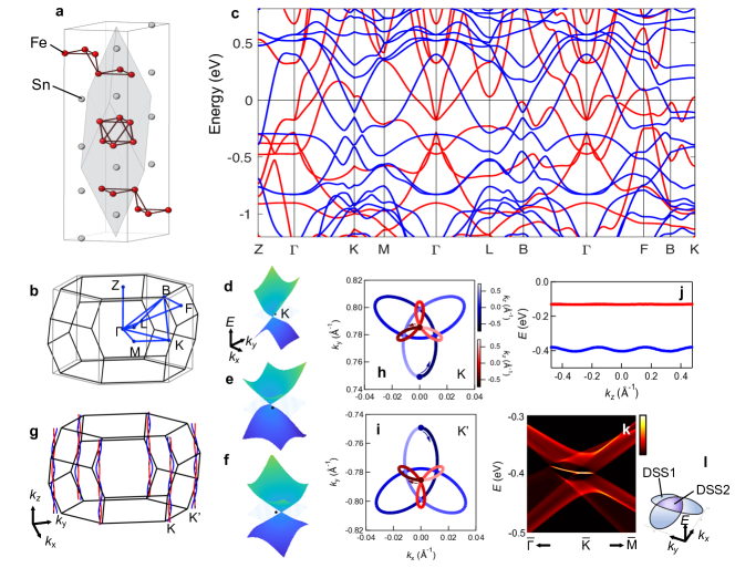
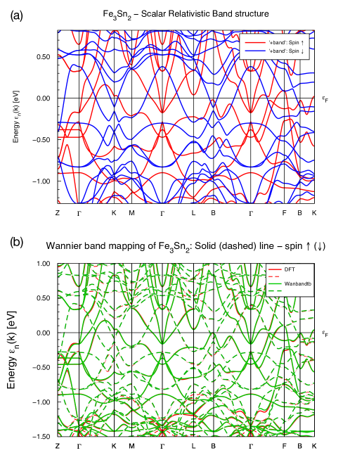
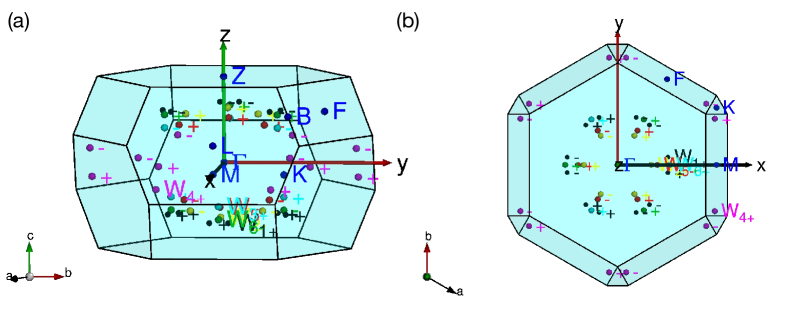
Having illustrated the generation of helical nodal lines in a simple A-B-C stacked kagome lattice model, in the following we turn to the DFT electronic structure of \ceFe3Sn2 in the absence of spin-orbit coupling – to test the relevance of the above picture in describing the system. The crystalline structure of \ceFe3Sn2 (Space group No.166 ) is illustrated in Fig. 2(a) in the conventional hexagonal unit cell, while the rhombohedral unit cell is highlighted in gray. Each unit cell contains a bilayer kagome structure that are further stacked in the A-B-C fashion. In Fig. 2(b) we show the rhombohedral BZ of \ceFe3Sn2 along with selected high symmetry points. We note that in addition to , , , , of the rhombohedral convention, we also include and of the hexagonal convention to better describe the Dirac electronic structure observed experimentally in the proximity of of the surface BZ [13]. The calculated electronic structure is shown in Fig. 2(c) along the high symmetry lines highlighted in Fig. 2(b). The majority spin states (illustrated in red) feature electron pockets centered near and a hole pocket close to , while the minority spin states (illustrated in blue) show a double Dirac structure displaced in energy in the vicinity of , as previously observed in angle-resolved photoemission experiments [13, 28, 35]. This suggests that DFT reasonably account for the electronic structure in \ceFe3Sn2. Hereafter we refer to the Dirac structure near -0.1 eV (-0.4 eV) as upper (lower) Dirac fermions, respectively.
Focusing on the upper Dirac dispersion, although we observe an apparent gap at similar to the DFT band structure reported in Ref. [35], via searching in the proximity of we find the gap closing and reopening through a single point at each constant cross-section (Band landscapes at selected planes for the upper nodal line are shown in Fig. 2(d-f)). A search near the lower Dirac dispersion yields similar results. Connecting the point nodes at each plane we obtain two sets of helical nodal lines as depicted in Fig. 2(g), where the nodal line for the upper Dirac fermion is shown in red, and lower Dirac fermions in blue. Both nodal lines wind around vertical in a helical fashion, similar to that of the simple tight-binding model as shown in Fig. 1(f,g), suggesting that the trigonal A-B-C stacking plays a key role in generating the helical nodal lines. A magnified view of the top projection of the helical nodal lines at and ’ can be found in Fig. 2(h) and (i) in the shape of hypotrochoids, where we use gradient scales as shown in Fig. 2(h) to sketch the evolution along . Near both nodal lines may be approximately described by the following functional form:
| (1) |
Here the band touching point is shifted to with respect to K point at given . For the upper (lower) nodal line, the parameters are () and () in units of Å-1, respectively. Here stands for the vertical distance between the kagome bilayer units; superscripts and stand for upper and lower nodal lines, respectively. The -evolution near ’ can be obtained by performing an inversion operation to that near (Fig. 2(i)).
The presence of sinusoidal components of both and implies the presence of both nearest layer and next nearest layer hopping terms in \ceFe3Sn2 (see Supplementary Materials), the latter not included in the simple nearest layer model discussed above in Fig. 1(f-h). We further examine the energy evolution of both the upper and lower nodal lines in Fig. 2(j). The closer confinement of the upper nodal lines to the verticals of and ’ is accompanied by a weaker out-of-plane dispersion illustrated in Fig. 2(j): the energy variation of the upper nodal line is on the order of 1.5 meV while for the lower is on the order of 11 meV, while both are significantly weaker as compared to the in-plane Dirac bandwidth eV. This corroborates the bulk quasi-2D nature and the absence of photon-energy dependence of the double Dirac structure observed in \ceFe3Sn2 [13].
To further elucidate the nature of the identified helical nodal lines, we have computed the Berry phase on loops around the nodal lines where is the Berry connection [36], with denoting the wave function at . Without spin-orbit coupling, a combined inversion and effective time-reversal symmetry dictates the quantization of the Berry phase as a binary invariant that takes either 0 or [8]. We have verified that both upper and lower nodal lines support a -Berry phase to the path integrals enclosing the nodal lines, suggesting that it is the the non-trivial Berry phase that protects the nodal lines in the present case. The -Berry phase here may be naturally connected to that of Dirac fermions in the 2D limit [37] and that more recently demonstrated in photoemission intensity analysis for bulk quasi-2D Dirac fermions derived from the kagome lattice in FeSn [22]. In the present system, due to a reduction of the symmetry from hexagonal to trigonal, the positions of the nodal lines are displaced from high symmetry lines; nevertheless their presence is robust and protected by the -Berry phase inherited from the 2D limit. In Fig. 5 we show that nodal lines centered at and are robust with increasing interplane hopping strength, as long as the two lines do not touch and hybridize with each other. We note that due to broken time reversal symmetry, each band touching point here in \ceFe3Sn2 is ferromagnetic and two-fold degenerate, which belongs to a similar class with the ferromagnetic nodal lines discussed in \ceCo2MnGa [5], \ceCo3Sn2S2 [12] and \ceFe3GeTe2 [43] in the absence of spin-orbit coupling.
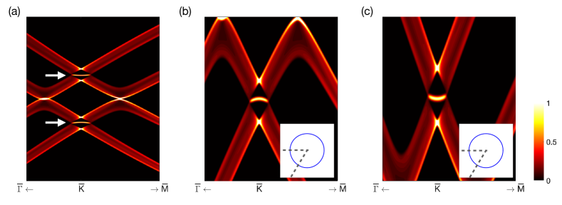
Additionally, we examine the surface states which originate from the hypotrochoid winding pattern of the lower nodal line in Fig. 2(k,l) (see Methods). The existence of a drumhead surface state in a nodal line semimetal may be illustrated in the following picture: for a given one may define a Zak phase along , and corresponds to a 1D topological insulator with zero energy edge states (here we restrict ourselves in the spinless case) and defines the region where surface states reside [3]. In Fig. 2(k), we find that in the present case ferromagnetic drumhead surface states appear once within the three side lobes (blue region labeled DSS1 in Fig. 2(l)) with and twice within the center surface momentum regime (purple region labeled DSS2 in Fig. 2(l)) . We expect the surface states in the DSS2 region to be more fragile and dependent on the surface potential than that within DSS1, as has been discussed for systems with multiple nodal loops [38]. The lobe structure of the flat surface bands adds new opportunties for potential correlated phenomena; moreover, with the sensitivity of the helical nodal line to interplane hopping, one may manipulate the connectivity and drive Lifshitz transitions of these lobe-wise drumhead surface states by hydrostatic pressure (see Fig. 15).
.3 Kane-Mele spin-orbit coupling in \ceFe3Sn2
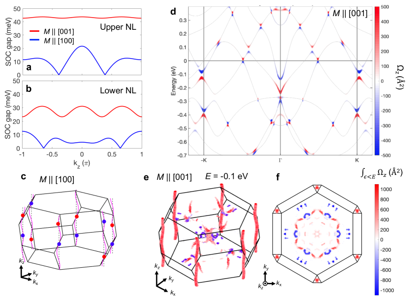
Having located the helical nodal lines in the proximity of and ’ in the absence of spin-orbit coupling, in the following we examine the fully relativistic electronic structure of \ceFe3Sn2. As \ceFe3Sn2 is known to be a soft ferromagnet [39], we consider both cases of moments in and out of the kagome lattice plane. With an out-of-plane magnetic moment, we find that both the upper and lower nodal lines are fully gapped with spin-orbit coupling, with the upper meV and lower Dirac gap meV as shown in Fig. 3(a,b). The in-plane magnetic moment induces a smaller gap, and the nodal lines remain gapless at two positions for both the upper and lower branches (Fig. 3(a,b)). This anisotropic coupling of with the Dirac electrons is consistent with a Kane-Mele type spin-orbit coupling in \ceFe3Sn2 as suggested in Refs. [13, 25]. These discrete remnant touching points correspond to Weyl points; we show Weyl points with the opposite chirality as blue and red circles in Fig. 3(c) for the case of the lower nodal line.
Next we elaborate on the out-of-plane ferromagnetic case where spin-orbit coupling introduces a full gap to the helical nodal lines. We have computed the resultant Berry curvature and its distribution along high symmetry lines ’-- in plane is shown in Fig. 3(d). We observe concentrated Berry curvature at the gapped nodes as expected for massive Dirac fermions [40], together with additional distribution of Berry curvatures from potential Weyl points (see also Fig. 14) [28]. near and ’ are found to be additive, which can be contrasted to the cancelling pattern at and ’ valleys in the inversion-symmetry-breaking and time-reversal-symmetric graphene [40]. The Berry curvature structure at both upper and lower Dirac gaps also exhibit the same sign. We further illustrate the distribution of integrated Berry curvature (here represents all states with energy below ) in the 3D BZ in Fig. 3(e,f) up to the upper Dirac gap ( eV), where columns of Berry curvature hot spots are confined along the stacked massive Dirac fermions. These massive Dirac fermions descend naturally from their 2D limit as kagome realizations of the Haldane model [41] and therefore in isolation form a 3D quantum anomalous Hall insulating phase [42]. In this context, we propose that chiral boundary modes can be detected at step edges of the kagome cleavage of \ceFe3Sn2 crystals at energies within the Dirac gap, similar to those recently demonstrated in a Mn-based kagome metal \ceTbMn6Sn6 [24]. Near we also observe less extended patches of Berry curvature intensities, the 3D nature of which suggests that they may originate from underlying Weyl fermions in the system [28]. The difference in momentum-space dimensionality leads to a response dominated by the extended features associated with the massive quasi-2D Dirac states (Fig. 3(e)).
Having demonstrated that nodal lines gapped by the interplay of ferromagnetic order and spin-orbit coupling in \ceFe3Sn2 serve as a strong source of Berry curvature and therefore contribute significantly to the intrinsic anomalous Hall conductivity (see Fig. 13)[13], it is instructive to compare the helical nodal lines identified here in \ceFe3Sn2 with the nodal lines discussed in the van der Waals ferromagnet \ceFe3GeTe2 [43]. In both cases, topological nodal lines are rendered strong sources of . We note that as compared with \ceFe3GeTe2, where contribution to is concentrated in the momentum space near the gapped nodal line along over its energy dispersion of 0.25 eV [43], such contributions in \ceFe3Sn2 is further concentrated energetically due to the weak energy variation of the massive Dirac fermions along the direction. Intriguingly, in \ceFe3GeTe2, it is also found that an out-of-plane moment maximizes the spin-orbit gap along the nodal line. Despite this similar sensitivity with the ferromagnetic moment orientation, we note that the spin-orbit coupling in \ceFe3Sn2 that opens the gaps at the Dirac nodes is different at the effective model level than that discussed for \ceFe3GeTe2 [43]. In the latter, an on-site spin-orbit coupling of the form lifts the degeneracy at that originates from orbital degrees of freedom of Fe -orbitals; this mechanism also applies to the models on the triangular lattices [44] and the orbitals on hexagonal closed packing cobalt layers [45], where an orbital degree of freedom is preserved for three-(or six-)fold rotation centers. In the context of the kagome lattice, the degeneracies of all orbitals are in principle lifted due to the low site symmetry. An onsite spin-orbit coupling term is therefore ineffective in opening a gap for the band crossing at the effective model level, rather the intersite form of spin-orbit coupling – introduced by Kane-Mele for the graphene lattice model based on orbitals [46], where the orbital degrees of freedom is quenched – is responsible for the gap opening at . The kagome lattice therefore provides a model platform for studying the Kane-Mele type spin-orbit coupling and its interplay with massive Dirac fermions. Clarifying the underlying microscopic mechanisms for such spin-orbit coupling terms will provide insights in future design of topological phases from the lattice point of view.
.4 Interplane hopping and layer degrees of freedom of Dirac fermions in \ceFe3Sn2
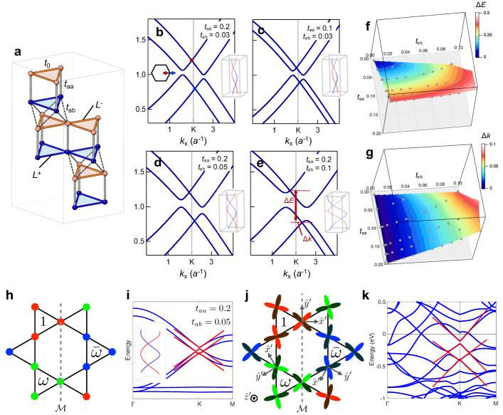
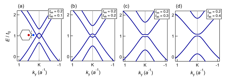
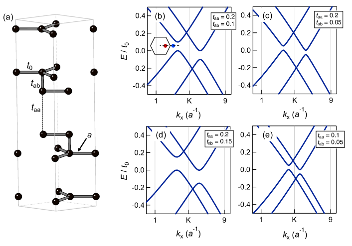
Having demonstrated that both upper and lower helical nodal lines in \ceFe3Sn2 can be captured by quasi-2D Dirac fermions subject to a Kane-Mele type spin-orbit coupling, in the following we examine the origin of the pair of Dirac fermions in the system. Expanding from the A-B-C stacked kagome model described above, we build a tight-binding model of an AA-BB-CC stacked kagome lattice illustrated in Fig. 4(a) to more accurately capture the iron sublattice of \ceFe3Sn2. A fundamental rhombohedral unit cell of this model includes six atoms, forming a pair of A-A stacked kagome bilayer. This pair provides a layer degree of freedom whose role we elucidate hereafter. Aside from the in-plane nearest neighbor hopping , we introduce two inequivalent inter-plane hopping integrals and . represents vertical hopping processes between aligned A-A (B-B, C-C) stacked sublattices, while denotes the nearest neighbor hopping between layers that are rotated by with each other (i.e., through A-B, B-C and C-A stacking).
First we find that parameter sets satisfying reproduces the experimental and numerical double Dirac structure in \ceFe3Sn2: bands obtained from several such and are shown in Fig. 4(b-e) and the corresponding nodal lines are shown as insets. The momentum line is highlighted in Fig. 4(b) inset. We note that setting considerably deforms the Dirac bands (Supplementary Materials Fig. 8) and yields band features inconsistent with either ARPES [13] or the DFT spectrum shown in Fig. 2(c). Hereon we focus on the evolution of the double Dirac structure with respect to and . In Fig. 4(b,d,e) a progressively increasing displaces the nodal lines farther from K, consistent with the simpler A-B-C model (see Supplementary Materials Fig. 5); meanwhile the energy splitting between upper and lower nodal lines stays constant. In contrast, by varying while keeping constant (Fig. 4(b,c)), the location of the nodal lines are unchanged while the energy splitting between upper and lower branches increases in proportion to . The respective dependence on and of the energy splitting and momentum displacement (both schematically illustrated in Fig. 4(e)) is also clear in the contour plots of and in the phase space (Fig. 4(f,g)). Further analysis of the eigenstates of the tight-binding Dirac states reveals that the upper/lower branches are predominately composed of bonding/antibonding superpositions of states residing respectively in layers and in Fig. 4(a), which are connected via .
An outstanding observation here is that and appear to play distinct roles to the Dirac fermions. It is instructive to adopt the following model in the vicinity of :
| (2) |
where and are Pauli matrices and is the Dirac velocity. represents the vertical distance of () hopping. represents the Dirac spinor per kagome layer (the basis wave function of within each layer is illustrated in Fig. 4(h)) while denotes the layer degree of freedom where . In Fig. 4(i) we illustrate the dispersion (red) as compared with the AA-BB-CC tight-binding model (blue) for . With , one can treat the last term of Eqn. 2 as a perturbation and project the four states to two sets; the resulting two eigenstate sub-sectors (upper () and lower () Dirac fermions) can be classified with ( and respectively), which are energetically split as . Projecting the terms into each sector, we derive a effective Hamiltonian as , where the Dirac points are moved to ( the vertical distance between the neighboring bilayer units), giving rise to helical nodal lines (see inset of Fig. 4(i)). From the formulation, it is clear that preserves an underlying sublattice (chiral) symmetry for the Dirac fermions [47], as a result of which terms perturb band touching points away from and but cannot generate either a gap or an energy shift to the degeneracy points. A similar model can be constructed for the DFT structure as we show in Fig. 4(j,k). The leading parameters are m/s, eV, eV (also see Methods), suggestive of a layer split nature of the two copies of Dirac fermions in \ceFe3Sn2 [13]. The layer origin of the upper and lower Dirac states is also consistent with the similar Berry curvature structure they exhibit as illustrated in Fig. 3(d).
| Fe | Fe | Fe | Fe | Fe | Fe | Sn(s) | Sn(s) | Sn(k) | Sn | |
|---|---|---|---|---|---|---|---|---|---|---|
| Lower Dirac cone | 33.0 | 23.8 | 10.9 | 9.9 | 9.1 | 1.7 | 0.4 | 9.2 | 1.5 | 0.5 |
| Upper Dirac cone | 49.4 | 9.6 | 16.6 | 15.0 | 4.3 | 1.3 | 0.2 | 1.8 | 1.6 | 0.3 |
We additionally analyzed the orbital characters of the Wannier function for the upper and lower Dirac fermions as summarized in Table 1. The predominant in-plane nature of both upper and lower Dirac fermions dictates reduced strength of and as compared to (we may estimate eV from via , where is the in-plane lattice constant), which further leads to the characteristic double Dirac structure in \ceFe3Sn2 (see Supplementary Materials for a more detailed description of the orbital-decomposed hopping pathways). Moreover, as can be inferred from Eqn. 2, and are decoupled from the -evolution of the nodal line energies, implying that higher order hopping terms are required to grant the Dirac fermions a considerable dispersion. This is consistent with the suppressed -dispersion and quasi-two-dimensionality of the bulk Dirac fermions suggested experimentally in \ceFe3Sn2 [13, 25]. We note that including an asymmetry to account for the breathing nature of the kagome lattices in \ceFe3Sn2 does not considerably alter the scenarios presented here (see Fig. 9). Through the above minimal AA-BB-CC model and expansion we establish \ceFe3Sn2 as an illustrative example of how rich stacking patterns and associated interplane coupling manifest in quasi-two-dimensional electronic materials. In Fig. 10 we illustrate that similar results can be obtained for a model of AA-BB-CC stacked honeycomb layers.
.5 Discussion
In summary, from a theoretical perspective, we have established \ceFe3Sn2 as a host of ferromagnetic helical nodal lines derived from a kagome network of iron. The peculiar presence of mixed A-A and A-B stacking patterns of kagome lattices in \ceFe3Sn2 causes the formation of helical nodal lines, gives rise to the layer splitting between upper and lower branches, and suppresses the -dispersion of these nodal lines. With an out-of-plane ferromagnetic order, the two sets of helical nodal lines are gapped out by spin-orbit coupling and serve as strong source of Berry curvatures. Gradually rotating the ferromagnetic moments from out-of-plane to in-plane orientations one may partially close the Dirac mass gap at discrete points and realize pairs of Weyl nodes located along the original helical nodal lines. In view of the soft ferromagnetic nature of the system we may anticipate novel electronic states at domain walls [48]; one especially exciting avenue lies in the skyrmion bubble structures observed earlier in \ceFe3Sn2 at room temperature [49], where the real space topological spin textures may entangle with the nodal lines and give rise to novel electronic responses [50].
A direct experimental observation of the drumhead surface states in \ceFe3Sn2 has remained elusive due in part to the weak interplane coupling of the form and a resulting limited radial size of the helical nodal lines. Further engineering of the interplane hopping and spin-orbit coupling in related intermetallic compounds that host trigonal stacking of kagome lattices may lead to experimentally detectable drumhead surface states [33]. We note that a recent tight-binding study of a type orbital on an A-B-C kagome lattice with enhanced out-of-plane hopping assisted by interlayer Sn atoms serves as a minimal model to generate vertical nodal rings and the ferromagnetic Weyl semimetallic phase in \ceCo3Sn2S2 [51]. This comparison suggests that with rational orbital engineering, intermetallic compound-based kagome lattices may provide a full spectrum of topological phases ranging from the 3D quantum anomalous Hall insulating phase [13, 22, 42] to the ferromagnetic Weyl semimetallic phase [12]; driving the topological phase transition between the two classes of phases are of extreme theoretical and experimental interest.
The implications of our study are beyond electronic structures of metallic systems. As trigonal stacking and rhombohedral symmetry are ubiquitous in naturally occuring kagome lattice materials [52, 54, 53, 55], including, for instance, the spin liquid hosting herbertsmithite [54], we expect that the helical nodal lines discussed here may be relevant not only in the electronic sector, but also in the magnonic or spinonic sectors [56], in the context of considerable inter-plane coupling. In view of the close resemblance of the kagome lattice with the honeycomb lattice [10, 31, 57], the above picture could be relevant, for example, in the Dirac-like Majorana fermionic spectrum in RuCl3 where the Ru honeycomb layers are A-B-C stacked [58].
I Methods
I.1 Density functional theory electronic structure calculations
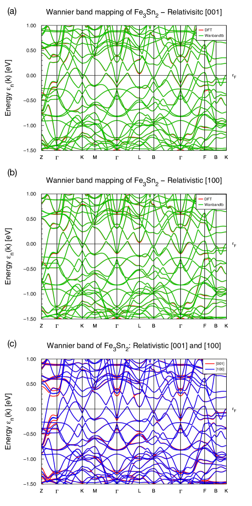
To compute the electronic and related properties of Fe3Sn2 we carry out the Density Functional Theory (DFT) calculations by using the full-potential local-orbital (FPLO) code [8], version 18.00-52. The exchange-correlation energy functional used is based on the parameterization of Perdew, Burke, and Ernzerhof (PBE-96) [60] within the generalized gradient approximation. A linear tetrahedron method with subdivisions in the full Brillouin zone was used for the momentum space integrations. The lattice parameters used in the calculation are and [61]. We consider the ground state in the ferromagnetic state and converge the self-consistent calculations within the scalar relativistic mode, and (four-component) fully relativistic mode of FPLO, with a self-consistent spin density better than . The total magnetic moments per unit cell (\ceFe6Sn4) for the converged ground states are 12.21 in scalar relativistic mode, 12.64 and 12.65 respectively for the fully relativistic mode with ferromagnetic state along [001] and [100] orientations. We note that the latter two values include orbital magnetic moments.
To carry out further analysis of the electronic structure, we derive the Wannier tight-binding Hamiltonian by projecting the Bloch states onto atomic orbital-like Wannier functions using the PYFPLO module of the FPLO package [8]. These localized Wannier basis states include Fe , , orbitals and Sn , orbitals. The Wannier model is converged with a grid sampling in the Brillouin zone. These derived Wannier Hamiltonians are then used to investigate the nodal Dirac structure and associated topological properties such as Berry curvatures [7].
I.2 \ceFe3Sn2 expansion and calculation of drumhead surface states
Here we give a more detailed expansion for \ceFe3Sn2 electronic structure near the double Dirac cones, as performed for the AA-BB-CC model in Eq. 2. The numerical projection is based on the Wannier construction (see main text and supplementary materials). The four-band effective Hamiltonian can be summarized as:
| (3) |
where (corresponding to m/s), eV, eV, eV, eV, eV, eV and eV. This effective model captures the helical nodal line structure for both upper and lower cones. Starting from this, we consider a finite thin-film slab geometry to shed light on the surface states associated with the helical nodes in \ceFe3Sn2. We found the drumhead surface states near K points as illustrated in Fig. 2(k) in the surface spectral function for the lower Dirac cone (similar drumhead surface states can be obtained for the upper Dirac cone).
II Acknowledgement
We are grateful to B. Lian, J.-S. You, and T. Kurumaji for fruitful discussions. This work was funded, in part, by the Gordon and Betty Moore Foundation EPiQS Initiative, Grant No. GBMF9070 to J.G.C. and NSF grant DMR-1554891. L.Y. and E.K. acknowledge support by the STC Center for Integrated Quantum Materials, NSF grant number DMR-1231319. L.Y. acknowledges support from the Heising-Simons Foundation. S.F. is supported by a Rutgers Center for Material Theory Distinguished Postdoctoral Fellowship. M.P.G. acknowledges the equipment grant supported by Alexander von Humboldt Foundation, Germany. J.v.d.B. acknowledges financial support from the German Research Foundation (Deutsche Forschungsgemeinschaft, DFG) via SFB1143 Project No. A5 and under German Excellence Strategy through the Würzburg-Dresden Cluster of Excellence on Complexity and Topology in Quantum Matter ct.qmat (EXC 2147, Project No. 390858490). The computations in this paper were run on the FASRC Cannon cluster supported by the FAS Division of Science Research Computing Group at Harvard University and at the computer clusters at IFW Dresden, Germany. S.F., M.P.G. and M.R. acknowledge the technical assistance from U. Nitzsche for the latter. J.L. acknowledges the support from the Hong Kong Research Grants Council (26302118, 16305019 and N_HKUST626/18).
References
- [1] A.A. Burkov, M.D. Hook, and L. Balents, Topological nodal semimetals, Phys. Rev. B 84 235126 (2011).
- [2] D. Takane, S. Souma, K. Nakayama, T. Nakamura, H. Oinuma, K. Hori, K. Horiba, H. Kumigashira, N. Kimura, T. Takahashi, and T. Sato, Observation of a Dirac nodal line in \ceAlB2, Phys. Rev. B 98, 041105(R) (2018).
- [3] Y.-H. Chan, C.-K. Chiu, M.Y. Chou, and A.P. Schnyder, \ceCa3P2 and other topological semimetals with line nodes and drumhead surface states, Phys. Rev. B, 93, 205132 (2016).
- [4] T. Bzdušek, Q. Wu, A. Rüegg, M. Sigrist, and A.A. Soluyanov, Nodal-chain metals, Nature, 538 75–78(2016).
- [5] G. Chang, S.-Y. Xu, X. Zhou, S.-M. Huang, B. Singh, B. Wang, I. Belopolski, J. Yin, S. Zhang, A. Bansil, H. Lin, and M.Z. Hasan, Topological Hopf and chain link semimetal states and their application to \ceCo2MnGa, Phys. Rev. Lett., 119, 156401 (2017).
- [6] T.T. Heikkilä, and G.E. Volovik, Nexus and Dirac lines in topological materials, New J. Phys., 17 093019 (2015).
- [7] Q.S. Wu, A.A. Soluyanov, and T. Bzdušek, Non-Abelian band topology in noninteracting metals, Science, 365, 1273-1277 (2019).
- [8] C. Fang, H. Weng, X. Dai, and Z. Fang, Topological nodal line semimetals, Chin. Phys. B, 25, 11 (2016).
- [9] S.-Y. Yang, H. Yang, E. Derunova, S.S.P. Parkin, B. Yan, and M.N. Ali, Symmetry demanded topological nodal-line materials, Adv. in Phys.: X, 3:1, 1414631 (2018).
- [10] T.T. Heikkilä, and G.E. Volovik, Dimensional crossover in topological matter: evolution of the multiple Dirac point in the layered system to the flat band on the surface, JETP Lett., 93, 59-65 (2011).
- [11] H. Weng, C. Fang, Z. Fang, B.A. Bernevig, and X. Dai, Weyl semimetal phase in noncentrosymmetric transition-metal monophosphides, Phys. Rev. X, 5, 011029 (2015).
- [12] E. Liu, Y. Sun, N. Kumar, L. Muechler, A. Sun, L. Jiao, S.-Y. Yang, D. Liu, A. Liang, Q. Xu, J. Kroder, V. Süß, H. Borrmann, C. Shekhar, Z. Wang, C. Xi, W. Wang, W. Schnelle, S. Wirth, Y. Chen, S.T.B. Goennenwein, and C. Felser, Giant anomalous Hall effect in a ferromagnetic kagome-lattice semimetal, Nat. Phys., 14 1125–1131 (2018).
- [13] L. Ye, M. Kang, J. Liu, F. von Cube, C.R. Wicker, T. Suzuki, C. Jozwiak, A. Bostwick, E. Rotenberg, D.C. Bell, L. Fu, R. Comin, and J.G. Checkelsky, Massive Dirac fermions in a ferromagnetic kagome metal, Nature, 555, 638–642 (2018).
- [14] M.Z. Hasan, and C.L. Kane, Colloquium: topological insulators, Rev. Mod. Phys., 82, 3045 (2010).
- [15] A.C. Neto, F. Guinea, N.M. Peres, K.S. Novoselov, and A.K. Geim, The electronic properties of graphene. Rev. Mod. Phys., 81 109 (2009).
- [16] R.L. Johnston, and R. Hoffmann, The kagomé net: Band theoretical and topological aspects, Polyhedron, 9, 1901-1911 (1990).
- [17] S.M. Young, S. Zaheer, J.C.Y. Teo, C.L. Kane, E.J. Mele, and A.M. Rappe, Dirac semimetal in three dimensions, Phys. Rev. Lett., 108, 140405 (2012).
- [18] S. Balendhran, S. Walia, H. Nili, S. Sriram, and M. Bhaskaran, Elemental Analogues of Graphene: Silicene, Germanene, Stanene, and Phosphorene, Small, 2015, 11, 640–652 (2014).
- [19] S. Nakatsuji, N. Kiyohara, and T. Higo, Large anomalous Hall effect in a non-collinear antiferromagnet at room temperature, Nature, 527, 212–215 (2015).
- [20] A.K. Nayak, J.E. Fischer, Y. Sun, B. Yan, J. Karel, A.C. Komarek, C. Shekhar, N. Kumar, W. Schnelle, J. Kübler, C. Felser, and S.S.P. Parkin, Large anomalous Hall effect driven by a nonvanishing Berry curvature in the noncolinear antiferromagnet \ceMn3Ge, Sci. Adv., 2, e1501870 (2016).
- [21] B.R. Ortiz, L.C. Gomes, J.R. Morey, M. Winiarski, M. Bordelon, J.S. Mangum, I.W.H. Oswald, J.A. Rodriguez-Rivera, J.R. Neilson, S.D. Wilson, E. Ertekin, T.M. McQueen, and E.S. Toberer, New kagome prototype materials: discovery of \ceKV3Sb5, \ceRbV3Sb5, and \ceCsV3Sb5, Phys. Rev. Mater., 3, 094407 (2019).
- [22] M. Kang, L. Ye, S. Fang, J.-S. You, A. Levitan, M. Han, J.I. Facio, C. Jozwiak, A. Bostwick, E. Rotenberg, M.K. Chan, R.D. McDonald, D. Graf, K. Kaznatcheev, E. Vescovo, D.C. Bell, E. Kaxiras, J. van den Brink, M. Richter, M.P. Ghimire, J.G. Checkelsky, and R. Comin, Dirac fermions and flat bands in the ideal kagome metal FeSn, Nat. Mater., 19 163-169 (2020).
- [23] M. Kang, S. Fang, L. Ye, H.C. Po, J. Denlinger, C. Jozwiak, A. Bostwick, E. Rotenberg, E. Kaxiras, J.G. Checkelsky, and R. Comin, Topological flat bands in frustrated kagome lattice CoSn, Nat. Commun., 11, 4004 (2020).
- [24] J.-X. Yin, W. Ma, T.A. Cochran, X. Xu, S.S. Zhang, H.-J. Tien, N. Shumiya, G. Cheng, K. Jiang, B. Lian, Z. Song, G. Chang, I. Belopolski, D. Multer, M. Litskevich, Z.-J. Cheng, X.P. Yang, B. Swidler, H. Zhou, H. Lin, T. Neupert, Z. Wang, N. Yao, T.-R. Chang, S. Jia, and M.Z. Hasan, Quantum-limit Chern topological magnetism in \ceTbMn6Sn6, Nature, 583, 533–536(2020).
- [25] L. Ye, M.K. Chan, R.D. McDonald, D. Graf, M. Kang, J. Liu, T. Suzuki, R. Comin, L. Fu, and J.G. Checkelsky, de Haas-van Alphen effect of correlated Dirac states in kagome metal \ceFe3Sn2, Nat. Comm., 10 4870 (2019).
- [26] A. Biswas, O. Iakutkina, Q. Wang, H.-C. Lei, M. Dressel, and E. Uykur, Spin-reorientation-induced band gap in \ceFe3Sn2: optical signatures of Weyl nodes, Phys. Rev. Lett., 125, 076403 (2020).
- [27] J.-X. Yin, S.S. Zhang, H. Li, K. Jiang, G.Chang, B.Zhang, B.Lian, C.Xiang, I. Belopolski, H. Zheng, T.A. Cochran, S.-Y. Xu, G. Bian, K. Liu, T.-R. Chang, H. Lin, Z.-Y. Lu, Z. Wang, S. Jia, W. Wang, and M.Z. Hasan, Giant and anisotropic many-body spin–orbit tunability in a strongly correlated kagome magnet, Nature, 562, 91–95(2018).
- [28] M. Yao, H. Lee, N. Xu, Y. Wang, J. Ma, O.V. Yazyev, Y. Xiong, M. Shi, G. Aeppli, Y. Soh, Switchable Weyl nodes in topological kagome ferromagnet \ceFe3Sn2, arXiv/1810.01514.
- [29] J.W. McClure, Electron energy band structure and electronic properties of rhombohedral graphite, Carbon, 7, 425-432 (1969).
- [30] R. Xiao, F. Tasnádi, K. Koepernik, J. W. F. Venderbos, M. Richter, and M. Taut, Density functional investigation of rhombohedral stacks of graphene: Topological surface states, nonlinear dielectric response, and bulk limit, Phys. Rev. B, 84, 165404 (2011).
- [31] C.-H. Ho, C.-P. Chang, and M.-F. Lin, Evolution and dimensional crossover from the bulk subbands in ABC-stacked graphene to a three-dimensional Dirac cone structure in rhombohedral graphite, Phys. Rev. B 93, 075437 (2016).
- [32] M. Otani, M. Koshino, Y. Takagi, and S. Okada, Intrinsic magnetic moment on (0001) surfaces of rhombohedral graphite, Phys. Rev. B, 81, 161403(R) (2010).
- [33] H. Henck, J. Avila, Z.B. Aziza, D. Pierucci, J. Baima, B. Pamuk, J. Chaste, D. Utt, M. Bartos, K. Nogajewski, B.A. Piot, M. Orlita, M. Potemski, M. Calandra, M.C. Asensio, F. Mauri, C. Faugeras, and A. Ouerghi, Flat electronic bands in long sequences of rhombohedral-stacked graphene, Phys. Rev. B, 97, 245421 (2018).
- [34] D. L. Bergman, C. Wu, and L. Balents, Band touching from real-space topology in frustrated hopping models, Phys. Rev. B, 78, 125104 (2008).
- [35] H. Tanaka, Y. Fujisawa, K. Kuroda, R. Noguchi, S. Sakuragi, C. Bareille, B. Smith, C. Cacho, S.W. Jung, T. Muro, Y. Okada, and T. Kondo, Three-dimensional electronic structure in ferromagnetic \ceFe3Sn2 with breathing kagome bilayers, Phys. Rev. B, 101, 161114(R) (2020).
- [36] G.P. Mikitik, and Y.V. Sharlai, Manifestation of Berry’s phase in metal physics, Phys. Rev. Lett., 82, 2147 (1999).
- [37] Y. Zhang, Y.-W. Tan, H.L. Stormer, and P. Kim , Experimental observation of the quantum Hall effect and Berry’s phase in graphene, Nature, 438, 201–204 (2005).
- [38] Y. Zhou, F. Xiong, X. Wan, and J. An, Hopf-link topological nodal-loop semimetals, Phys. Rev. B, 97, 155140 (2018).
- [39] B. Malaman, D. Fruchart, and G. Le Caer, Magnetic properties of \ceFe3Sn2. II. Neutron diffraction study (and Mossbauer effect), J. Phys. F: Met. Phys., 8 2389 (1978).
- [40] D. Xiao, W. Yao, and Q. Niu, Valley-contrasting physics in graphene: magnetic moment and topological transport, Phys. Rev. Lett., 99, 236809 (2007).
- [41] F.D.M. Haldane, Model for a quantum Hall effect without Landau levels: condensed-matter realization of the ”parity anomaly”, Phys. Rev. Lett., 61, 2015 (1988).
- [42] A.A. Burkov, and L. Balents, Weyl semimetal in a topological insulator multilayer, Phys. Rev. Lett., 107, 127205 (2011).
- [43] K. Kim, J. Seo, E. Lee, K.-T. Ko, B.S. Kim, B.G. Jang, J.M. Ok, J. Lee, Y.J. Jo, W. Kang, J.H. Shim, C. Kim, H.W. Yeom, B.I. Min, B.-J. Yang, and J.S. Kim, Large anomalous Hall current induced by topological nodal lines in a ferromagnetic van der Waals semimetal, Nat. Mater., 17 794–799 (2018).
- [44] J. Zhang, B. Zhao, Y. Xue, T. Zhou, and Z. Yang, Coupling effect of topological states and Chern insulators in two-dimensional triangular lattices, Phys. Rev. B, 97, 125430 (2018).
- [45] G.H.O. Daalderop, P.J. Kelly, and M.F.H. Schuurmans, Magnetic anisotropy of a free-standing Co monolayer and of multilayers which contain Co monolayers, Phys. Rev. B, 50, 9989 (1994).
- [46] C.L. Kane, and E.J. Mele, topological order and the quantum spin Hall effect, Phys. Rev. Lett., 95, 146802 (2005).
- [47] Y. Hatsugai, T. Morimoto, T. Kawarabayashi, Y. Hamamoto, and H. Aoki, Chiral symmetry and its manifestation in optical responses in graphene: interaction and multilayers, New J. Phys., 15 035023 (2013).
- [48] Y. Araki, A. Yoshida, and K. Nomura, Universal charge and current on magnetic domain walls in Weyl semimetals, Phys. Rev. B, 94, 115312 (2016).
- [49] Z. Hou, W. Ren, B. Ding, G. Xu, Y. Wang, B. Yang, Q. Zhang, Y. Zhang, E. Liu, F. Xu, W. Wang, G. Wu, X. Zhang, B. Shen, and Z. Zhang, Observation of various and spontaneous magnetic skyrmionic bubbles at room temperature in a frustrated kagome magnet with uniaxial magnetic anisotropy, Adv. Mater., 2017 1701144 (2017).
- [50] J.L. Lado, and J. Fernández-Rossier, Quantum anomalous Hall effect in graphene coupled to skyrmions, Phys. Rev. B, 92, 115433 (2015).
- [51] A. Ozawa, and K. Nomura, Two-orbital effective model for magnetic Weyl semimetal in kagome-lattice Shandite, J. Phys. Soc. Jpn., 88, 123703 (2019).
- [52] G. Xu, B. Lian, and S.-C. Zhang, Intrinsic quantum anomalous Hall effect in the kagome lattice \ceCs2LiMn3F12, Phys. Rev. Lett., 115, 186802 (2015).
- [53] I.I. Mazin, H.O. Jeschke, F. Lechermann, H. Lee, M. Fink, R. Thomale, and R. Valentí, Theoretical prediction of a strongly correlated Dirac metal, Nat. Commun., 5 4261 (2014).
- [54] M.R. Norman, Colloquium: Herbertsmithite and the search for the quantum spin liquid, Rev. Mod. Phys., 88, 041002 (2016).
- [55] N. Hänni, M. Frontzek, J. Hauser, D. Cheptiakov, and K. Krämer, Low temperature phases of \ceNa2Ti3Cl8 revisited, Z. Anorg. Allg. Chem., 2017, 2063–2069 (2017).
- [56] Y. Ran, M. Hermele, P.A. Lee, and X.-G. Wen, Projected-wave-function study of the spin-1/2 Heisenberg model on the kagomé lattice, Phys. Rev. Lett., 98, 117205 (2007).
- [57] S.S. Pershoguba, S. Banerjee, J. C. Lashley, J. Park, H. Ågren, G. Aeppli, and A.V. Balatsky, Dirac magnons in honeycomb ferromagnets, Phys. Rev. X, 8, 011010 (2018).
- [58] A. Banerjee, C.A. Bridges, J.-Q. Yan, A. A. Aczel, L. Li, M.B. Stone, G.E. Granroth, M.D. Lumsden, Y. Yiu, J. Knolle, S. Bhattacharjee, D.L. Kovrizhin, R. Moessner, D.A. Tennant, D.G. Mandrus, and S.E. Nagler, Proximate Kitaev quantum spin liquid behaviour in a honeycomb magnet, Nat. Mater., 15, 733–740 (2016).
- [59] K. Koepernik, and H. Eschrig, Full-potential nonorthogonal local-orbital minimum-basis band-structure scheme, Phys. Rev. B, 59, 1743 (1999). https://www.fplo.de/.
- [60] J.P. Perdew, K. Burke, and M. Ernzerhof, Generalized gradient approximation made simple, Phys. Rev. Lett., 77, 3865 (1996).
- [61] K. Persson, Materials Data on \ceFe3Sn2 (SG:166) by Materials Project, http://doi.org/10.17188/1201722, United States (2016).
- [62] T. Fukui, Y. Hatsugai, and H. Suzuki, Chern numbers in discretized Brillouin zone: efficient method of computing (spin) Hall conductances. J. Phys. Soc. Jpn., 74, 1674 (2005). \justify
Supplementary Information
Ferromagnetic helical nodal line and Kane-Mele spin-orbit
coupling in kagome metal \ceFe3Sn2
III Evolution of helical nodal line with interplane hopping
In Fig. 5 we examine the evolution of the helical nodal lines with a gradually increasing out-of-plane hopping , where Fig. 5(a,b), (c,d), (e,f) show the top and 3D views with , respectively. We find that in the limit , the trajectory of the nodal line (here the origin is set at and ’ of the hexagonal Brillouin zone) may be described by the following polar coordinate at each :
| (4) |
where the chirality takes at (), respectively. Here we use to denote the kagome lattice constant and the vertical interlayer distance. The radial displacement from is roughly proportional to and with a growing a trigonal warping of the nodal line trajectories becomes apparent (see Fig. 5(c,e)). Nevertheless the existence of the nodal lines remains robust as long as the blue and red nodal lines do not touch.
IV Drumhead surface states in kagome stacks
Here we first construct a simple ABC stacked kagome lattice model to illustrate the drumhead head surface states associated with the helical nodal lines. In an ABC-stacked kagome slab crystal, with s-wave orbitals on kagome sites, the Hamiltonian can be derived as
| (5) |
where are the layer unit index within the slab, and 2D momentum . stands for intraplane hopping while and feature the nearest and next-nearest hopping, respectively:
| (6) |
and . Here is the intra-layer nearest neighbor coupling between kagome sites, the dominant inter-layer coupling to the first (second) nearest layer in the out-of-plane direction. The vectors used are , , and . The corresponding bulk Hamiltonian takes the following form:
| (7) |
In Fig. 6, we show that by introducing multiple out-of-plane hopping terms () we are capable of reproducing the three-fold hypotrochoid patterns of the helical nodal lines. The helical nodal line structures in the bulk and the associated drumhead surface states in the surface spectral function are shown in Fig. 6(a) for and in Fig. 6(b) for , respectively. These nodal lines are found to be protected by the combined symmetry which quantizes the Berry phase in a loop around the helical nodal line to integer multiples of . Despite that the real crystal structure of \ceFe3Sn2 contains kagome bilayers, we note that this simplified ABC model captures the essential features of the drumhead surface states derived from a approach as adopted in the main text. We have also verified that additionally taking into account the AA-BB-CC structure does not appear to alter the features of the nodal lines or drumhead surface states (illustrated in Fig. 7, only showing the case with nearest layer hopping for clarity).
V AA-BB-CC kagome and honeycomb lattice model
In this section we provide additional results from the AA-BB-CC kagome model and also describe a closely related AA-BB-CC honeycomb lattice model. In Fig. 8 we explore the variation of the band structure near at with an increasing strength of . In Fig. 8(a,b) while in Fig. 8(c,d) . The vertically split double Dirac structure gradually evolves to resemble a quadratic band touching with increasing . We note that the two limiting cases (, ) resemble the A-A stacked and A-B stacked bilayer graphene near and zero energy, respectively [1].
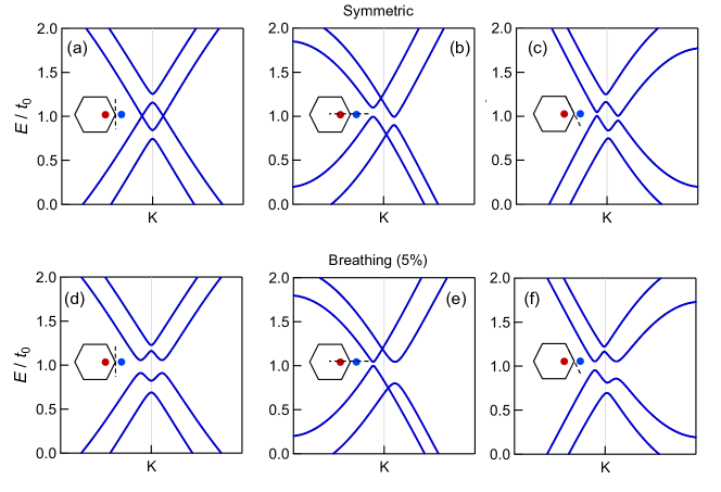
The breathing kagome lattice structure of \ceFe3Sn2 inspires us to explore the introduction of a small asymmetry to the double Dirac helices. By contrasting the symmetric (Fig. 9(a-c)) and the asymmetric (Fig. 9(d-f)) models we note that the upper and lower band crossings near and their helical nature is largely unaffected. The primary effect of the asymmetry within the kagome plane beyond a threshold strength is the opening of a full gap at where the upper and lower Dirac branches meet.
In Fig. 10 we show an AA-BB-CC honeycomb model which yields very similar results with the kagome model presented in the main text: controls the splitting between upper and lower Dirac states and displaces the nodal lines from high symmetry and of the hexagonal Brillouin zone.
VI DFT electronic structure calculations, Wannier tight-binding Hamiltonian and applications
VI.1 Wannier tight-binding Hamiltonians
VI.2 Anomalous Hall conductivity
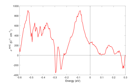
With the Wannier tight-binding Hamiltonians, the Berry curvatures of the electronic bands and the integrated anomalous Hall response can be computed [7]. In Fig. 13, we show the calculated anomalous Hall conductivity as a function of Fermi level. The features of the total conductivity can be identified with the gap locations of the quasi-two-dimensional massive Dirac fermions with FM order along axis. For example, the peak around eV corresponds to the massive gap of the upper Dirac structure.
VI.3 Weyl Points Near Fermi Level
In this section we elaborate on underlying Weyl points in Fe3Sn2 electronic structure. With the Wannier tight-binding Hamiltonians, these Weyl points can be identified using the PYFPLO module of the FPLO package [8]. In Fe3Sn2 crystal with FM order in the direction, we have identified six types of Weyl points near the Fermi level (see Table 2 for the characteristics).
| Energy (meV) | Multiplicity | ||||
|---|---|---|---|---|---|
| W1 | -33.7 | 12 | -0.183 | 0.028 | 0.160 |
| W2 | -17.3 | 6 | -0.123 | 0.0 | 0.148 |
| W3 | -14.3 | 6 | -0.191 | 0.0 | 0.111 |
| W4 | 17.2 | 12 | -0.354 | 0.168 | 0.045 |
| W5 | 25.1 | 6 | -0.144 | 0.0 | 0.117 |
| W6 | 36.1 | 6 | -0.191 | 0.0 | 0.149 |
VII Pressure modification of the helical nodal lines in \ceFe3Sn2
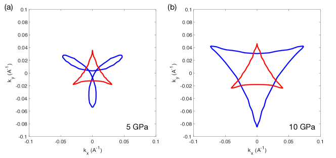
In this section, we briefly consider the perturbations on the helical nodal line electronic structure under an external hydrostatic pressure applied to the crystal. This hydrostatic pressure can compress the crystal structure and also reduce the inter-layer distance between kagome sheets. This in turn, modifies the inter-layer coupling energy between Dirac states on kagome sheets. From the effective models, these coupling energies are shown to control helical nodal line characteristics, such as the size of the helical nodal line orbit and the Fermi surface topology of the drumhead surface states.
The pressure effects are simulated via density functional theory calculations implemented in the Vienna ab initio simulation package (VASP) [2, 3]. The electronic structure is computed based on the Projector Augmented-Wave [5] pseudopotential formalism and Perdew–Burke-Ernzerhof (PBE) [4] parametrized exchange-correlation energy functional. The \ceFe3Sn2 crystals are relaxed under an external hydrostatic pressure of 5 GPa and 10 GPa (up to around 3% changes in the lattice constants). The helical nodal line structures are shown in Fig. 15. The enhanced inter-layer coupling energies results in the enlarged size of the helix at higher pressure. We note that the shape of nodal line trajectories are DFT code-dependent; nevertheless our results suggest that pressure is an effective tuning parameter of the nodal lines in \ceFe3Sn2.
VIII expansion for the Dirac structures and the Wannier projection
In this section, we discuss the numerical projection procedure to derive the expansion of the (double) Dirac structure based on the Wannier projection principle [6]. Such effective low-energy models can capture the evolution of Dirac structure in the momentum space. We focus on a small region that is confined near in the plane while periodically extended along . This differs from the conventional expansion around a single point, and also the full Wannier transformation which requires the full Brillouin zone sampling [6] to derive the localized state.
The effective modeling here features both approaches. First, we derive a conventional model with respect to in-plane and identify the proper basis functions to support such expansion. Next, to capture full information, we utilize the Wannier transformation in the out-of-plane direction and derive the localized basis. In short, the final basis functions for the low energy expansion are extended in , directions, but localized along . In other words, these states are the Dirac states in each layer of kagome sheets, and they form the intricate structure (along ) via interplane couplings. In the following, we first motivate the construction of these Dirac states on individual kagome layers (initial projectors) and then derive effective models that account for the energy dispersions and layer hybridizations. We then apply this construction to the ideal AA-BB-CC kagome model and the full \ceFe3Sn2 electronic structure.
VIII.1 Initial Wannier projector for the Dirac states
In a simple kagome lattice layer, with sites decorated by the isotropic (single) -wave orbitals, the flat band and the Dirac doublets at K point has the underlying wave function textures as shown in Fig. 16(a,b). From the wave function pattern, the symmetry eigenvalues at various rotation centers can be inferred. The pairs of the Dirac doublet states are used as the initial basis projection in the double Dirac structure from AA-BB-CC kagome model.
For \ceFe3Sn2, the AA-BB-CC kagome structure is decorated by more complex orbitals. The multi-orbital nature of the electronic structure can give rise to multiple copies of the Dirac structure in the spectrum, from different set of orbital orientations. However, for the double Dirac structure in \ceFe3Sn2, the band character is summarized (Table 1 in main text) with local coordinate frame defined in Fig. 16(c). This motivates us to adopt the initial basis functions for projections as shown in Fig. 16(d), compounded with the local orbitals. In the FM (spin-polarized) ordered phase of \ceFe3Sn2, we only consider the minority spin channel that form the double Dirac cones. There are two projected states in a single layer, and two in-equivalent layers, hence a total of four basis states.
In the following, we carry out the procedure and show this projection is non-singular with the initial states. That is, the double Dirac manifold can be captured and expanded by our initial basis functions without obstructions.
VIII.2 AA-BB-CC kagome model expansion and double Dirac structure
In this section, we discuss the expansion for the Dirac structures in the AA-BB-CC kagome lattice model (see main text Fig. 4(a)). The full tight-binding model has 6 bands, and the electronic properties for the 4 bands of the Dirac cones are shown in Fig. 4(b-e) under different model parameters. The goal is to derive a 4-band effective model to capture these Dirac states and their nodal lines.
In a given unit cell, there is an AA bilayer unit with two kagome sheets. denotes the (sub-)layer index. Within each layer, there are two initial states defined at K point for the projections as discussed above, and are denoted as (with for the Dirac doublets, and to indicate the bilayer unit index in stacking direction). These states are extended in and localized in individual kagome sheets along . Now we can perform the Wannier transformation [6] along (in-plane momentum fixed at K) for the double Dirac structure. This can be viewed effectively as a transformation in a one-dimensional system with momentum . The double Dirac structure in AA-BB-CC with eigenstates defines a projector for the four eigenstates in double Dirac cones. To span the periodic manifold, we project by the Fourier-transformed initial states above . We define the new projected states . Although they are not orthonormal, an unitary transformation can be used as in the Wannier transformation [6] to obtain an orthonormal basis set from the overlap matrix . An inverse Fourier transform of can give the updated Dirac state in the real space . As with the initial states above, these new states are extended in the in-plane direction, and exponentially localized in the direction. We note that the projection is always non-singular in , and these four states are able to completely span the double Dirac structure without any obstructions.
After obtaining this proper basis set , the effective Hamiltonian can be derived by computing the matrix elements . To capture the helical nodal lines, we derive this expansion to include the constant terms and linear terms in . These terms capture the on-site energy shifts, inter-layer coupling between single-layer Dirac states, and linear terms for the Dirac dispersion.
Generally, the four band model can be written as
| (8) |
The rotation symmetry can be used to derive the selection rules of the matrix elements and simplify the Hamiltonian. One feature of the rhombohedral stacking order is that, the pair of Dirac doubles on a single layer has for a rotation axis at the hexagon center. The neighboring layers are relatively shifted which lead to different symmetry eigenvalue pairs of Dirac doublets. This results in a specific form of non-zero matrix elements. To summarize in a compact form, we use to denote the (sub)-layer index and for the Dirac doublets. The effective four band model is shown as in the main text and demonstrates the helical nodal line structure:
| (9) |
We note that the prefactor in arises from 6 pairs of inter-layer couplings in an AB bilayer unit.
VIII.3 \ceFe3Sn2 expansion and double Dirac structure
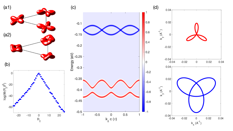
For the bulk \ceFe3Sn2 crystal, the kagome structure is the same as the AA-BB-CC kagome system above despite the additional Sn spacer layer unit. The double Dirac cone structure also resembles the ideal AA-BB-CC kagome system. Among the five Fe orbitals, local orbitals are the dominant components in the double cones. With the full Wannier model to describe the \ceFe3Sn2 electronic structure, we perform the same projection procedure as above to project the double Dirac cone states. The initial wave function projectors are as the above AA-BB-CC kagome case, and with additional local orbitals attached. Similarly, we find the projection can be carried out as well without any singularity and obstruction. The final projected Wannier basis set for expansion is shown in Fig. 17(a), for the Dirac doublets on a single kagome sheet. These Wannier objects also show a strong exponential decay in the wave function weights along direction away from the center layer as in Fig. 17(b). One of the doublets (Fig. 17 (a1)) preserves better a local component compared to the other (Fig. 17 (a2)). The stronger out-of-plane component in (a2) may be associated with a symmetry-allowed hopping channel to its nearest next layer neighbor, which is forbidden by symmetry for (a1).
With this proper basis set, the effective Hamiltonian can be derived up to the linear term in . The results are elaborated in Methods. One feature we find from the effective model projection is that, the coupling in the AA bilayer unit is larger than the coupling in the AB bilayer unit between Dirac states. As the result, the double Dirac cone splitting arises from the bonding / anti-bonding of the Dirac cone states in an AA bilayer unit (despite the Sn spacer layer in between) as in Fig. 17(c) for . Within this low-energy Hamiltonian, the helical nodal lines can be captured as shown in Fig. 17(d).
We expand on the observation , despite a smaller interlayer distance in an AB bilayer unit, compared to an AA bilayer unit. This appears at first sight contradictory to larger microscopic atomic orbital couplings derived from the (full) Wannier Hamiltonian based on the DFT calculations, as we show in Table 3. Hereafter we elaborate on the origin of the reduced effective coupling in the effective Hamiltonian. The main difference between the (full) Wannier model and the effective model is that, the irrelevant states are integrated out and the renormalized basis states are derived within the effective model. This process naturally mixes states of different orbital types, locations, and renormalizes the coupling matrix elements. In the derived Wannier state, the electron density is spread out across several nearby kagome layers. To be precise, in an AB bilayer, the wavefunction for the Wannier state centered at A, B can be decomposed into layer-resolved components at layer A, B. Generally, can spread further exponentially as shown in Fig. 17(b), but we focus only on the components within an AB bilayer unit. In particular, the Wannier state centered on the kagome A layer in an AB bilayer has a non-zero density weight about 1/5 on the neighboring kagome B layer compared to the density weight on the kagome A layer. In the context of orbital textures, the dominant components for weights on kagome A layer are the in-plane orbitals ( and ), as used in the initial projector. In contrast, the weights on the kagome B layer are mostly out-of-plane orbitals. These out-of-plane orbital contents can be viewed as induced from enhanced atomic couplings involving out-of-plane orbital sectors compared to the fully in-plane ones in an AB bilayer, as tabulated in Table 3.
Thanks to the layer-dependent orbital texture of the effective basis states, the matrix element for the effective contains contributions from different channels between these components within the AB bilayer . For the dominant contributions and channels within an AB bilayers, the numerical numbers are shown in Table 4, and a cancellation is observed between these channels which reduces the effective coupling by one order of magnitude compared to the microscopic values. We note that numerically, there are additional cancelling terms for wavefunction components spread into further kagome and Sn spacer layers, which further suppresses .
On the other hand, the microscopic interplane coupling across A-A stacking in Table 3 appear small compared that across A-B stacking. However, we noticed the effective coupling can be mediated via the intermediate Sn orbitals from the spacer layer unit, and the states can efficiently tunnel and hybridize. This leads to the enhanced effective couplings, and the bonding / anti-bonding states across the Sn layer for the double cone structure.
In summary, the effective basis states as the composite objects strongly renormalize the coupling parameters from the microscopic values. The geometric stacking pattern and the spacer layer electronic properties can affect the effective theory. It would be interesting to consider the design of these factors and the implications on the electronic structure.
|
| -130 | 131 | |
| 170 | -130 |
References
- [1] C. J. Tabert and E. J. Nicol, Dynamical conductivity of AA-stacked bilayer graphene, Phys. Rev. B 86, 075439 (2012).
- [2] G. Kresse, and J. Furthmüller, Efficient iterative schemes for ab initio total-energy calculations using a plane-wave basis set. Phys. Rev. B 54, 11169 (1996).
- [3] G. Kresse and J. Furthmüller, Efficiency of ab-initio total energy calculations for metals and semiconductors using a plane-wave basis set. Comput. Mater. Sci. 6, 15 (1996).
- [4] J. P. Perdew, and K. Burke, and M. Ernzerhof, Generalized gradient approximation made simple. Phys. Rev. Lett. 77, 3865 (1996).
- [5] P. E. Blöchl, Projector augmented-wave method. Phys. Rev. B 50, 17953 (1994).
- [6] N. Marzari, and A. A. Mostofi, and J. R. Yates, and I. Souza, and D. Vanderbilt Maximally localized Wannier functions: theory and applications. Rev. Mod. Phys. 84, 1419 (2012).
- [7] T. Fukui, and Y. Hatsugai, and H. Suzuki, Chern numbers in discretized Brillouin zone: efficient method of computing (spin) Hall conductances. J. Phys. Soc. Jpn. 74, 1674 (2005).
- [8] https://www.fplo.de/